

Operating Instructions
Page 86
... is caused by a temperature change. • Do not open the unit, make sure you close it within 5 minutes to keep light from damaging the copy drum. • When copying to sheets 35" ×45" (90 cm ×115 cm) or larger, make two sided copies. • If you open the covers...
... is caused by a temperature change. • Do not open the unit, make sure you close it within 5 minutes to keep light from damaging the copy drum. • When copying to sheets 35" ×45" (90 cm ×115 cm) or larger, make two sided copies. • If you open the covers...
Service Manual
Page 15
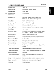
DRUM PROCESSES 1-4 4. MECHANICAL COMPONENT LAYOUT 1-6 5. EXPOSURE 2-6 3.1 OVERVIEW 2-6 3.2 PAPER AND ORIGINAL FEED 2-7 3.2.1 Basic Operation (Manual Feed 2-7 3.2.2 Original Jam Check Timing 2-9 3.2.3 Drive mechanism 2-10 3.3 FL ...TONER DENSITY CONTROL 2-16 4.4.1 Toner Near End Condition 2-17 SM i A163 SPECIFICATIONS 1-1 2. Table of Contents Rev. 06/2004 OVERALL MACHINE INFORMATION 1. DRIVE LAYOUT 1-7 6. DRUM 2-1 1.1 DRUM CHARACTERISTICS 2-1 1.2 DRUM DRIVE 2-2 2. CHARGE 2-3 2.1 OVERVIEW 2-3 2.2 CHARGE CORONA CIRCUIT 2-4 2.3 CORONA UNIT VENTILATION 2-5 3.
DRUM PROCESSES 1-4 4. MECHANICAL COMPONENT LAYOUT 1-6 5. EXPOSURE 2-6 3.1 OVERVIEW 2-6 3.2 PAPER AND ORIGINAL FEED 2-7 3.2.1 Basic Operation (Manual Feed 2-7 3.2.2 Original Jam Check Timing 2-9 3.2.3 Drive mechanism 2-10 3.3 FL ...TONER DENSITY CONTROL 2-16 4.4.1 Toner Near End Condition 2-17 SM i A163 SPECIFICATIONS 1-1 2. Table of Contents Rev. 06/2004 OVERALL MACHINE INFORMATION 1. DRIVE LAYOUT 1-7 6. DRUM 2-1 1.1 DRUM CHARACTERISTICS 2-1 1.2 DRUM DRIVE 2-2 2. CHARGE 2-3 2.1 OVERVIEW 2-3 2.2 CHARGE CORONA CIRCUIT 2-4 2.3 CORONA UNIT VENTILATION 2-5 3.

Service Manual
Page 19
... 6.2.1 Preparation 5-34 6.2.2 Separation Corona Wire Replacement 5-35 6.2.3 Transfer Corona Wire Replacement 5-35 7. Rev. 06/2004 4.6 PICK-OFF PAWL UNIT REMOVAL 5-18 4.7 GRID VOLTAGE ADJUSTMENT 5-19 4.8 DRUM CURRENT ADJUSTMENT 5-20 4.8.1 Charge Current Adjustment 5-22 4.8.2 Transfer Current Adjustment 5-23 4.8.3 Separation Current Adjustment 5-24 5.
... 6.2.1 Preparation 5-34 6.2.2 Separation Corona Wire Replacement 5-35 6.2.3 Transfer Corona Wire Replacement 5-35 7. Rev. 06/2004 4.6 PICK-OFF PAWL UNIT REMOVAL 5-18 4.7 GRID VOLTAGE ADJUSTMENT 5-19 4.8 DRUM CURRENT ADJUSTMENT 5-20 4.8.1 Charge Current Adjustment 5-22 4.8.2 Transfer Current Adjustment 5-23 4.8.3 Separation Current Adjustment 5-24 5.
Service Manual
Page 25
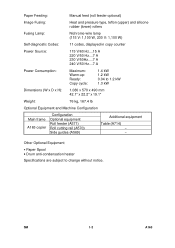
...) Multi-Copy: 1 to 1 only Automatic Reset: 2 minutes after copying is finished (can be set to 1, 3, 4, or 5 minutes or to no auto reset) Photoconductor: Organic photoconductor drum Drum Charge: Single-wire with grid wires (Negative Charge) Reproduction Ratio: 1 : 1 (±0.5%) Exposure System: Slit exposure via fiber optic array Exposure Lamp: Fluorescent lamp (26 W) Development...
...) Multi-Copy: 1 to 1 only Automatic Reset: 2 minutes after copying is finished (can be set to 1, 3, 4, or 5 minutes or to no auto reset) Photoconductor: Organic photoconductor drum Drum Charge: Single-wire with grid wires (Negative Charge) Reproduction Ratio: 1 : 1 (±0.5%) Exposure System: Slit exposure via fiber optic array Exposure Lamp: Fluorescent lamp (26 W) Development...
Service Manual
Page 26
... Hz....7 A Power Consumption: Maximum: Warm-up: Ready: Copy cycle: 1.4 kW 1.2 kW 0.04 to change without notice. SM 1-2 A163 Other Optional Equipment • Paper Spool • Drum anti-condensation heater Specifications are subject to 1.2 kW 1.3 kW Dimensions (W x D x H): 1,080 x 570 x 490 mm 42.1" x 22.2" x 19.1" Weight: 76 kg, 167.4 lb Optional Equipment and...
... Hz....7 A Power Consumption: Maximum: Warm-up: Ready: Copy cycle: 1.4 kW 1.2 kW 0.04 to change without notice. SM 1-2 A163 Other Optional Equipment • Paper Spool • Drum anti-condensation heater Specifications are subject to 1.2 kW 1.3 kW Dimensions (W x D x H): 1,080 x 570 x 490 mm 42.1" x 22.2" x 19.1" Weight: 76 kg, 167.4 lb Optional Equipment and...
Service Manual
Page 28
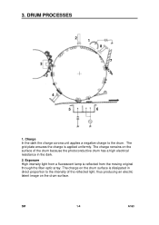
... uniformly. The charge remains on the surface of the reflected light, thus producing an electric latent image on the drum surface is dissipated in the dark. 2. The charge on the drum surface. SM 1-4 A163 DRUM PROCESSES 2 1 8 7 3 4 5 6 1. The grid plate ensures the charge is reflected from the moving original through the fiber optic array...
... uniformly. The charge remains on the surface of the reflected light, thus producing an electric latent image on the drum surface is dissipated in the dark. 2. The charge on the drum surface. SM 1-4 A163 DRUM PROCESSES 2 1 8 7 3 4 5 6 1. The grid plate ensures the charge is reflected from the moving original through the fiber optic array...
Service Manual
Page 29
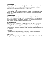
Development The magnetic developer brush on the development roller comes in contact with the latent image on the drum surface. 8. Then a strong negative charge is fed to the drum surface, at the exact timing, to align the copy paper and the developed image on the paper and breaking the... electrostatic attraction between the toner and the drum, thus making image transfer easier. 5. The negative charge pulls the toner particles from the quenching lamp electrically neutralizes the surface of the copy...
Development The magnetic developer brush on the development roller comes in contact with the latent image on the drum surface. 8. Then a strong negative charge is fed to the drum surface, at the exact timing, to align the copy paper and the developed image on the paper and breaking the... electrostatic attraction between the toner and the drum, thus making image transfer easier. 5. The negative charge pulls the toner particles from the quenching lamp electrically neutralizes the surface of the copy...
Service Manual
Page 30
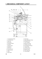
4. Pressure Roller 8. Paper Spool SM 14. Fiber Optic Array 25. Fusing Exit Rollers 6. OPC Drum 10. Paper Registration Rollers 16. Charge Corona Unit 20. 2nd Original Feed Roller 21. Cleaning Blade 1-6 A163 Gas Spring 9. Development Unit 17. Toner Cartridge 18. T/S ...
4. Pressure Roller 8. Paper Spool SM 14. Fiber Optic Array 25. Fusing Exit Rollers 6. OPC Drum 10. Paper Registration Rollers 16. Charge Corona Unit 20. 2nd Original Feed Roller 21. Cleaning Blade 1-6 A163 Gas Spring 9. Development Unit 17. Toner Cartridge 18. T/S ...
Service Manual
Page 31
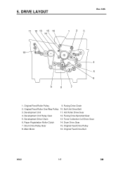
Exit Unit Drive Belt 3. Hot Roller Drive Gear 4. Drum Drive Gear 7. DRIVE LAYOUT Rev. 5/95 11 12 13 15 16 14 1 23 10 4 5 6 9 8 7 1. Fusing Drive Chain 2. Toner Collection Coil Drive Gear 6. Drum Drive Relay Gear 15. Original Feed Drive Belt A163 1-7 SM Original Feed Drive Pulley 8. Main Motor 16. Original Feed Roller One Way Pulley 10. Development Unit Relay Gear 12. Paper Registration Roller Clutch 14. Development Unit 11. Fusing Drive Sprocket/Gear 5. 5. Original Feed Roller Pulley 9. Development Drive Chain 13.
Exit Unit Drive Belt 3. Hot Roller Drive Gear 4. Drum Drive Gear 7. DRIVE LAYOUT Rev. 5/95 11 12 13 15 16 14 1 23 10 4 5 6 9 8 7 1. Fusing Drive Chain 2. Toner Collection Coil Drive Gear 6. Drum Drive Relay Gear 15. Original Feed Drive Belt A163 1-7 SM Original Feed Drive Pulley 8. Main Motor 16. Original Feed Roller One Way Pulley 10. Development Unit Relay Gear 12. Paper Registration Roller Clutch 14. Development Unit 11. Fusing Drive Sprocket/Gear 5. 5. Original Feed Roller Pulley 9. Development Drive Chain 13.
Service Manual
Page 32
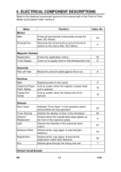
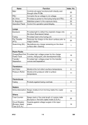
... the electrical component layout on to supply toner to the development unit. 31 Solenoids Pick-off Pawl Moves the pick-off pawls against the drum. 6 Switches Main Supplies power to Point (Water proof paper) index numbers. Drives all mechanical components except the fans. (DC Motor) ...32 Removes the ozone built up around the drum section to the ozone filter. (DC Motor) 5 Magnetic Clutches Registration Drives the registration rollers. 30 Toner Supply Turns on the reverse side ...
... the electrical component layout on to supply toner to the development unit. 31 Solenoids Pick-off Pawl Moves the pick-off pawls against the drum. 6 Switches Main Supplies power to Point (Water proof paper) index numbers. Drives all mechanical components except the fans. (DC Motor) ...32 Removes the ozone built up around the drum section to the ozone filter. (DC Motor) 5 Magnetic Clutches Registration Drives the registration rollers. 30 Toner Supply Turns on the reverse side ...
Service Manual
Page 33
... 22 21 15 23 10 Lamps Exposure Provides light to reflect the original's image onto the drum (fluorescent lamp). 2 Fusing Provides heat to the fusing unit. 3 Pre-Transfer (PTL) Reduces the charge on the drum surface prior to dc voltage. Converts the ac voltage to image transfer. 20 Quenching (QL) ...Neutralizes any charge remaining on the drum surface after cleaning. 1 Power Packs Charge/Bias/Grid Provides high voltage power for the charge Power Pack corona, charge grid, and development bias. ...
... 22 21 15 23 10 Lamps Exposure Provides light to reflect the original's image onto the drum (fluorescent lamp). 2 Fusing Provides heat to the fusing unit. 3 Pre-Transfer (PTL) Reduces the charge on the drum surface prior to dc voltage. Converts the ac voltage to image transfer. 20 Quenching (QL) ...Neutralizes any charge remaining on the drum surface after cleaning. 1 Power Packs Charge/Bias/Grid Provides high voltage power for the charge Power Pack corona, charge grid, and development bias. ...
Service Manual
Page 37
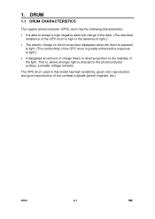
...the photoconductor surface, a smaller voltage remains. DRUM 1.1 DRUM CHARACTERISTICS The organic photoconductor (OPC) drum has the following characteristics: • It is able to accept a high negative electrical charge in the dark. (The electrical resistance of the OPC drum is high in this model has high sensitivity,..., and good reproduction of the light. 1. The OPC drum used in the absence of light.) • The electric charge on the drum surface dissipates when the drum is exposed to light. (The conductivity of the OPC drum is greatly enhanced by exposure to light.) • It...
...the photoconductor surface, a smaller voltage remains. DRUM 1.1 DRUM CHARACTERISTICS The organic photoconductor (OPC) drum has the following characteristics: • It is able to accept a high negative electrical charge in the dark. (The electrical resistance of the OPC drum is high in this model has high sensitivity,..., and good reproduction of the light. 1. The OPC drum used in the absence of light.) • The electric charge on the drum surface dissipates when the drum is exposed to light. (The conductivity of the OPC drum is greatly enhanced by exposure to light.) • It...
Service Manual
Page 38
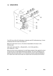
... motor [B] is on , the drive is transmitted to the drum in the following way: main motor drive gear [C] ⇒ idle gears [D] ⇒ drum drive gear [E] ⇒ drum flange [F] ⇒ drum When the drum knob is tightened, the right flange presses firmly against the drum so that the drum is also transmitted to the original feed rollers [G] through...
... motor [B] is on , the drive is transmitted to the drum in the following way: main motor drive gear [C] ⇒ idle gears [D] ⇒ drum drive gear [E] ⇒ drum flange [F] ⇒ drum When the drum knob is tightened, the right flange presses firmly against the drum so that the drum is also transmitted to the original feed rollers [G] through...
Service Manual
Page 39
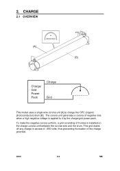
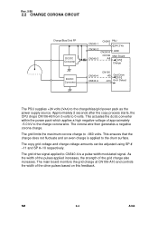
A163 2-3 SM 2. The corona unit generates a corona of negative ions when a high negative voltage is installed on the charge corona unit between the corona wire and the drum. To make the negative corona uniform, a grid consisting of the charge potential. CHARGE 2.1 OVERVIEW [A] [B] Charge/ Grid Power Pack Charge Grid This model uses a single wire corona unit [A] to it by the charge/grid power pack. This grid drains off any charge in excess of --860 volts, thus preventing fluctuation of 8 wires is applied to charge the OPC (organic photoconductor) drum [B].
A163 2-3 SM 2. The corona unit generates a corona of negative ions when a high negative voltage is installed on the charge corona unit between the corona wire and the drum. To make the negative corona uniform, a grid consisting of the charge potential. CHARGE 2.1 OVERVIEW [A] [B] Charge/ Grid Power Pack Charge Grid This model uses a single wire corona unit [A] to it by the charge/grid power pack. This grid drains off any charge in excess of --860 volts, thus preventing fluctuation of 8 wires is applied to charge the OPC (organic photoconductor) drum [B].
Service Manual
Page 40
... pack as the power supply source. The corona wire then generates a negative corona charge. The grid drive signal applied to CN340-4 is applied to the drum surface. This ensures that the charge does not fluctuate and an even charge is a pulse width modulated signal. Rev. 5/95 2.2 CHARGE CORONA CIRCUIT Charge/Bias...
... pack as the power supply source. The corona wire then generates a negative corona charge. The grid drive signal applied to CN340-4 is applied to the drum surface. This ensures that the charge does not fluctuate and an even charge is a pulse width modulated signal. Rev. 5/95 2.2 CHARGE CORONA CIRCUIT Charge/Bias...
Service Manual
Page 41
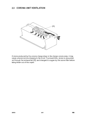
To prevent this, ozone is vacuumed out through the exhaust fan [A], and changed to oxygen by the corona charge stays in the charge corona area, it may cause uneven corona charging to the drum. A163 2-5 SM 2.3 CORONA UNIT VENTILATION [A] If ozone produced by the ozone filter before being blown out of the copier.
To prevent this, ozone is vacuumed out through the exhaust fan [A], and changed to oxygen by the corona charge stays in the charge corona area, it may cause uneven corona charging to the drum. A163 2-5 SM 2.3 CORONA UNIT VENTILATION [A] If ozone produced by the ozone filter before being blown out of the copier.
Service Manual
Page 42
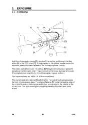
...the leading edge of the exposure lamp output. EXPOSURE 3.1 OVERVIEW [F] [D] [H] [E] [G] [I ] monitors the intensity of the original to the OPC drum [C]. The original registration sensor [G] detects when the original leading edge passes the front of the exposure glass surface.) The exposure lamp is a 140 V,... 26 W fluorescent lamp. This ensures that original registration sensor detects the original at the same speed as the drum's peripheral velocity. The light sensor [I ] [B] [A] [C] Light from the exposure lamp [A] reflects off the original and through the fiber...
...the leading edge of the exposure lamp output. EXPOSURE 3.1 OVERVIEW [F] [D] [H] [E] [G] [I ] monitors the intensity of the original to the OPC drum [C]. The original registration sensor [G] detects when the original leading edge passes the front of the exposure glass surface.) The exposure lamp is a 140 V,... 26 W fluorescent lamp. This ensures that original registration sensor detects the original at the same speed as the drum's peripheral velocity. The light sensor [I ] [B] [A] [C] Light from the exposure lamp [A] reflects off the original and through the fiber...
Service Manual
Page 43
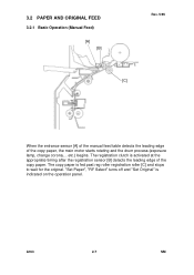
... is activated at the appropriate timing after the registration sensor [B] detects the leading edge of the copy paper, the main motor starts rotating and the drum process (exposure lamp, change corona,... 3.2 PAPER AND ORIGINAL FEED 3.2.1 Basic Operation (Manual Feed) [A] [B] Rev. 5/95 [C] When the entrance sensor [A] of the manual feed table detects...
... is activated at the appropriate timing after the registration sensor [B] detects the leading edge of the copy paper, the main motor starts rotating and the drum process (exposure lamp, change corona,... 3.2 PAPER AND ORIGINAL FEED 3.2.1 Basic Operation (Manual Feed) [A] [B] Rev. 5/95 [C] When the entrance sensor [A] of the manual feed table detects...
Service Manual
Page 44
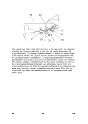
... glass. Then, the original exits the machine. At the appropriate time after the original is reflected through the fiber optics array [G] to the drum as the original passes between the platen plate [D] and exposure glass [E] and from there to be fed again. At the appropriate time, the...The original is pulled by the 1st original feed roller [A] just after either the original or copy paper exits, the image creation process (drum process) stops. [B] [D] [A] [C] [F] [G] [E] The original feed rollers rotate with the rotation of the original, and the "Set Original" indicator turns off...
... glass. Then, the original exits the machine. At the appropriate time after the original is reflected through the fiber optics array [G] to the drum as the original passes between the platen plate [D] and exposure glass [E] and from there to be fed again. At the appropriate time, the...The original is pulled by the 1st original feed roller [A] just after either the original or copy paper exits, the image creation process (drum process) stops. [B] [D] [A] [C] [F] [G] [E] The original feed rollers rotate with the rotation of the original, and the "Set Original" indicator turns off...
Service Manual
Page 46
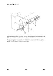
3.2.3 Drive Mechanism [D] [A] [B] [C] The original feed rollers are rotated by the main motor as mentioned in the drum drive section. The paper registration rollers [A] are driven through the original feed drive pulley and belt by the main motor [B] through the gears [C] and the paper registration clutch [D]. SM 2-10 A163
3.2.3 Drive Mechanism [D] [A] [B] [C] The original feed rollers are rotated by the main motor as mentioned in the drum drive section. The paper registration rollers [A] are driven through the original feed drive pulley and belt by the main motor [B] through the gears [C] and the paper registration clutch [D]. SM 2-10 A163