
English Manual
Page 3
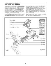
... on a decal attached to return upon approval ™ Health & Fitness, Inc. Cycling is .125" MKT. To help us assist you * rMhuostmbee.able to 1.35" by 3.40", corner radius is an effective exercise for HOME® (1-800-469-4663). The PROFORM XP 90 number before you have... questions Before reading further, please familiarize yourself with the parts labeled in the 831.21522.1. The model number is N subject to the exercise cycle (see the front convenience...
... on a decal attached to return upon approval ™ Health & Fitness, Inc. Cycling is .125" MKT. To help us assist you * rMhuostmbee.able to 1.35" by 3.40", corner radius is an effective exercise for HOME® (1-800-469-4663). The PROFORM XP 90 number before you have... questions Before reading further, please familiarize yourself with the parts labeled in the 831.21522.1. The model number is N subject to the exercise cycle (see the front convenience...
English Manual
Page 4
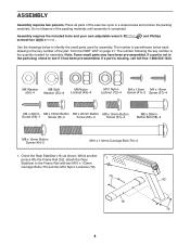
... not in a cleared area and remove the packing materials. Place all parts of the packing materials until assembly is completed. Do not dispose of the exercise cycle in the parts bag, check to the Frame Rail with two M10 x 112mm Carriage Bolts (76) and two M10 Nylon Locknuts (72). 76 52...
... not in a cleared area and remove the packing materials. Place all parts of the packing materials until assembly is completed. Do not dispose of the exercise cycle in the parts bag, check to the Frame Rail with two M10 x 112mm Carriage Bolts (76) and two M10 Nylon Locknuts (72). 76 52...
English Manual
Page 5
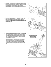
...to the Frame with two M10 x 112mm 76 Carriage Bolts (76) and two M10 Nylon Locknuts (72). 3. Gently pull the upper end of the Frame (1), attach the Front 2 Stabilizer to the Frame (1) with three M8 x 19mm Button Screws (40) and three M8 Split Washers (55). 2. Be careful to avoid pinching ...the Wire Harnesses (42, 43). 4 Avoid pinching the wire harnesses during this step. 2 42 40 43 55 40 55 55 40 1 5 Attach the Upright with two M8 x 19mm Button Screws (40) and two M8 Split 3 Washers (55). While another person lifts the front of the Upper Wire...
...to the Frame with two M10 x 112mm 76 Carriage Bolts (76) and two M10 Nylon Locknuts (72). 3. Gently pull the upper end of the Frame (1), attach the Front 2 Stabilizer to the Frame (1) with three M8 x 19mm Button Screws (40) and three M8 Split Washers (55). 2. Be careful to avoid pinching ...the Wire Harnesses (42, 43). 4 Avoid pinching the wire harnesses during this step. 2 42 40 43 55 40 55 55 40 1 5 Attach the Upright with two M8 x 19mm Button Screws (40) and two M8 Split 3 Washers (55). While another person lifts the front of the Upper Wire...

English Manual
Page 6
... Assembly to the Seat Bracket (11) with four M6 x 16mm Button Screws (8) and four M6 Washers 6 9 (66). 11 3 55 61 58 10 61 55 11 7. Attach the Seat (9) to the Seat Bracket (11) with three M6 x 20mm Button Screws (63). 66 8 7 31 66 8 11 63 63 6 Make sure that the Nylon... Locknuts are resting in the hexagonal holes in the same way. 5 55 61 49 3 6. Attach a Handlebar (3) to the Seat Bracket (11) with four M8 x 16mm Button Screws (61) and four M8 Split Washers (55). Orient the Seat Carriage Assembly (10...
... Assembly to the Seat Bracket (11) with four M6 x 16mm Button Screws (8) and four M6 Washers 6 9 (66). 11 3 55 61 58 10 61 55 11 7. Attach the Seat (9) to the Seat Bracket (11) with three M6 x 20mm Button Screws (63). 66 8 7 31 66 8 11 63 63 6 Make sure that the Nylon... Locknuts are resting in the hexagonal holes in the same way. 5 55 61 49 3 6. Attach a Handlebar (3) to the Seat Bracket (11) with four M8 x 16mm Button Screws (61) and four M8 Split Washers (55). Orient the Seat Carriage Assembly (10...

English Manual
Page 7
Attach a Bumper (51) to the Upper Wire Harness (42). alkaline batteries are oriented as shown. 10 50 Battery... lever back up. The Console (4) requires four 1.5V "D" batteries (not 9 included); Next, insert four batteries into the Upright (2). 57 80 Attach the Console (4) to the Console (4) with two M4 x 12mm Screws (41) as shown by the diagrams inside of the Frame Rail (52).... battery compart- Then, reattach the battery covers to avoid pinching the wire harnesses. 57 42 Wire Harness 2 7 Attach the Book Holder (23) to the Upright (2) with an M4 x 20mm Screw (56).
Attach a Bumper (51) to the Upper Wire Harness (42). alkaline batteries are oriented as shown. 10 50 Battery... lever back up. The Console (4) requires four 1.5V "D" batteries (not 9 included); Next, insert four batteries into the Upright (2). 57 80 Attach the Console (4) to the Console (4) with two M4 x 12mm Screws (41) as shown by the diagrams inside of the Frame Rail (52).... battery compart- Then, reattach the battery covers to avoid pinching the wire harnesses. 57 42 Wire Harness 2 7 Attach the Book Holder (23) to the Upright (2) with an M4 x 20mm Screw (56).


