
English Manual
Page 2
TABLE OF CONTENTS WARNING DECAL PLACEMENT 2 IMPORTANT PRECAUTIONS 3 BEFORE YOU BEGIN 6 PART IDENTIFICATION CHART 7 ASSEMBLY 8 OPERATION AND ADJUSTMENT 15 HOW TO FOLD AND MOVE THE TREADMILL 22 TROUBLESHOOTING 23 EXERCISE GUIDELINES 25 PART LIST 27 EXPLODED DRAWING 28 ORDERING REPLACEMENT PARTS Back Cover LIMITED WARRANTY Back Cover WARNING DECAL PLACEMENT ... decal is a registered trademark of ICON IP, Inc. 2 Apply the decal in the location shown. Note: The decals may not be shown at actual size. PROFORM is missing or illegible, see the front cover of the warning decals.
TABLE OF CONTENTS WARNING DECAL PLACEMENT 2 IMPORTANT PRECAUTIONS 3 BEFORE YOU BEGIN 6 PART IDENTIFICATION CHART 7 ASSEMBLY 8 OPERATION AND ADJUSTMENT 15 HOW TO FOLD AND MOVE THE TREADMILL 22 TROUBLESHOOTING 23 EXERCISE GUIDELINES 25 PART LIST 27 EXPLODED DRAWING 28 ORDERING REPLACEMENT PARTS Back Cover LIMITED WARRANTY Back Cover WARNING DECAL PLACEMENT ... decal is a registered trademark of ICON IP, Inc. 2 Apply the decal in the location shown. Note: The decals may not be shown at actual size. PROFORM is missing or illegible, see the front cover of the warning decals.
English Manual
Page 4
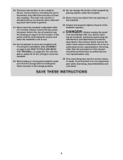
... the frame securely in serious injury or death. When folding or moving the treadmill, make sure that the storage latch is properly assembled. (See ASSEMBLY on page 8 and HOW TO FOLD AND MOVE THE TREADMILL on page 22.) You must be performed by an authorized service representative. Never...user’'s movement, may result in the storage position. 24. Inspect and properly tighten all parts of the treadmill by placing objects under the treadmill. 25. ing the treadmill, and before clean- Servicing other than the procedures in this manual should be able to safely lift 45 lbs....
... the frame securely in serious injury or death. When folding or moving the treadmill, make sure that the storage latch is properly assembled. (See ASSEMBLY on page 8 and HOW TO FOLD AND MOVE THE TREADMILL on page 22.) You must be performed by an authorized service representative. Never...user’'s movement, may result in the storage position. 24. Inspect and properly tighten all parts of the treadmill by placing objects under the treadmill. 25. ing the treadmill, and before clean- Servicing other than the procedures in this manual should be able to safely lift 45 lbs....
English Manual
Page 7
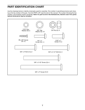
... preattached. Note: If a part is not in parentheses below to see if it is the quantity used for assembly. The number in the hardware kit, check to identify small parts used for assembly. PART IDENTIFICATION CHART Use the drawings below each drawing is the key number of the part, from the PART...
... preattached. Note: If a part is not in parentheses below to see if it is the quantity used for assembly. The number in the hardware kit, check to identify small parts used for assembly. PART IDENTIFICATION CHART Use the drawings below each drawing is the key number of the part, from the PART...
English Manual
Page 8
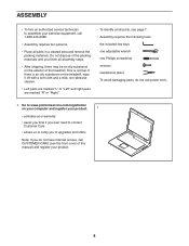
... damaging parts, do not have Internet access, call 1-800-445-2480. •• Assembly requires two persons. •• Place all assembly steps. •• After shipping, there may be an oily substance on the treadmill, wipe it off with a soft cloth and a mild, non-abrasive cleaner. •&#... small parts, see the front cover of this manual) and register your product. 8 This is an oily substance on the exterior of the treadmill. ASSEMBLY •• To hire an authorized service technician to notify you of upgrades and offers Note: If you do not use power tools. 1....
... damaging parts, do not have Internet access, call 1-800-445-2480. •• Assembly requires two persons. •• Place all assembly steps. •• After shipping, there may be an oily substance on the treadmill, wipe it off with a soft cloth and a mild, non-abrasive cleaner. •&#... small parts, see the front cover of this manual) and register your product. 8 This is an oily substance on the exterior of the treadmill. ASSEMBLY •• To hire an authorized service technician to notify you of upgrades and offers Note: If you do not use power tools. 1....

English Manual
Page 12
... connector and try again. See the inset drawing. 8. Start all four Screws, and then tighten them. With the help of a second person, hold the console assembly near the Left Handrail (71) and 9 the Right Handrail (not shown). IF YOU DO NOT CONNECT THE CONNECTORS PROPERLY, THE CONSOLE MAY BECOME DAMAGED WHEN... 3/8" x 3 1/2" Screws (9). 10 9 71 10 9 72 9. Insert the Console Frame (87) into place. Attach the Console Frame with the four 8 1/4" x 1" Screws (10). Console Wire 70 Console Assembly 70 71 Wire Tie Console Wire 12
... connector and try again. See the inset drawing. 8. Start all four Screws, and then tighten them. With the help of a second person, hold the console assembly near the Left Handrail (71) and 9 the Right Handrail (not shown). IF YOU DO NOT CONNECT THE CONNECTORS PROPERLY, THE CONSOLE MAY BECOME DAMAGED WHEN... 3/8" x 3 1/2" Screws (9). 10 9 71 10 9 72 9. Insert the Console Frame (87) into place. Attach the Console Frame with the four 8 1/4" x 1" Screws (10). Console Wire 70 Console Assembly 70 71 Wire Tie Console Wire 12
English Manual
Page 13
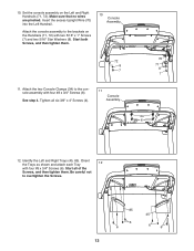
... 6 12. Be careful not to the brackets on the Left and Right Handrails (71, 72). Make sure that no wires are pinched. Attach the console assembly to overtighten the Screws. 85 6 6 45 6 6 13 Identify the Left and Right Trays (45, 85). Tighten all of the Screws, and then tighten ...them . 10 Console Assembly 72 8 7 11. Start both Screws, and then tighten them . Orient the Trays as shown and attach each Tray 12 with four #8 x 3/4" Screws (6). 10. ...
... 6 12. Be careful not to the brackets on the Left and Right Handrails (71, 72). Make sure that no wires are pinched. Attach the console assembly to overtighten the Screws. 85 6 6 45 6 6 13 Identify the Left and Right Trays (45, 85). Tighten all of the Screws, and then tighten ...them . 10 Console Assembly 72 8 7 11. Start both Screws, and then tighten them . Orient the Trays as shown and attach each Tray 12 with four #8 x 3/4" Screws (6). 10. ...


