
Uk Manual
Page 1
c/o HI Group PLC Express Way Whitwood, West Yorkshire WF10 5QJ UK CAUTION Read all precautions and instructions in the space above for future reference. If you have questions, or if there are missing parts, please contact us: Call: 08457 089 009 From Ireland: 053 92 36102 Website: www.iconsupport.eu E-mail: Visit www.iconsupport.eu Write: ICON Health & Fitness, Ltd. PFEVEL74008.1 Serial No. Write the serial number in this manual before using this manual for reference. Serial Number Decal QUESTIONS? Keep this equipment. USERʼS MANUAL www.iconeurope.com Model No.
c/o HI Group PLC Express Way Whitwood, West Yorkshire WF10 5QJ UK CAUTION Read all precautions and instructions in the space above for future reference. If you have questions, or if there are missing parts, please contact us: Call: 08457 089 009 From Ireland: 053 92 36102 Website: www.iconsupport.eu E-mail: Visit www.iconsupport.eu Write: ICON Health & Fitness, Ltd. PFEVEL74008.1 Serial No. Write the serial number in this manual before using this manual for reference. Serial Number Decal QUESTIONS? Keep this equipment. USERʼS MANUAL www.iconeurope.com Model No.
Uk Manual
Page 2
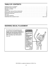
... PRECAUTIONS 3 BEFORE YOU BEGIN 4 ASSEMBLY 5 HOW TO USE THE ELLIPTICAL EXERCISER 13 MAINTENANCE AND TROUBLESHOOTING 22 EXERCISE GUIDELINES 23 PART LIST 25 EXPLODED DRAWING 26 ORDERING REPLACEMENT PARTS Back Cover WARNING DECAL PLACEMENT This drawing shows the location(s) of ICON IP, Inc. 2 PROFORM is missing or illegible, see the front cover of...
... PRECAUTIONS 3 BEFORE YOU BEGIN 4 ASSEMBLY 5 HOW TO USE THE ELLIPTICAL EXERCISER 13 MAINTENANCE AND TROUBLESHOOTING 22 EXERCISE GUIDELINES 23 PART LIST 25 EXPLODED DRAWING 26 ORDERING REPLACEMENT PARTS Back Cover WARNING DECAL PLACEMENT This drawing shows the location(s) of ICON IP, Inc. 2 PROFORM is missing or illegible, see the front cover of...
Uk Manual
Page 3
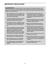
...through the use of this product. 1. Keep your physician. Keep children under age 12 and pets away from moisture and dust. Use your elliptical exerciser at least 3 ft. (1 m) of clearance in serious injury or death. Inspect and properly tighten all times. 8. Various factors, ...including the userʼs movement, may result in the front and rear of your elliptical exerciser and 2 ft. (0.6 m) on your back. 11. IMPORTANT PRECAUTIONS WARNING: To reduce the risk of serious injury, read all important...
...through the use of this product. 1. Keep your physician. Keep children under age 12 and pets away from moisture and dust. Use your elliptical exerciser at least 3 ft. (1 m) of clearance in serious injury or death. Inspect and properly tighten all times. 8. Various factors, ...including the userʼs movement, may result in the front and rear of your elliptical exerciser and 2 ft. (0.6 m) on your back. 11. IMPORTANT PRECAUTIONS WARNING: To reduce the risk of serious injury, read all important...
Uk Manual
Page 4
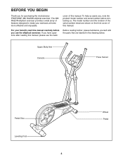
The 380 RAZOR elliptical exerciser provides a wide array of this manual. To help us . Upper Body Arm Console Pulse Sensor Pedal Disc Leveling Foot 4 Wheel Pedal For your workouts ... back cover of this manual carefully before contacting us assist you, note the product model number and serial number before you for purchasing the revolutionary PROFORM® 380 RAZOR elliptical exerciser. BEFORE YOU BEGIN Thank you use the...
The 380 RAZOR elliptical exerciser provides a wide array of this manual. To help us . Upper Body Arm Console Pulse Sensor Pedal Disc Leveling Foot 4 Wheel Pedal For your workouts ... back cover of this manual carefully before contacting us assist you, note the product model number and serial number before you for purchasing the revolutionary PROFORM® 380 RAZOR elliptical exerciser. BEFORE YOU BEGIN Thank you use the...

Uk Manual
Page 5
In addition to the included tool(s), assembly requires a Phillips screwdriver wrench , and a rubber mallet . , an adjustable As you assemble the elliptical exerciser, use power tools for assembly. M6 Locknut (77)-14 M8 Locknut (82)-8 M6 Washer (35)-2 M10 Split Washer (78)-6 M4 x... avoid damaging plastic parts, do not use the drawings below each drawing is the quantity needed for assembly. Do not dispose of the elliptical exerciser in parentheses below to see if it has been preassembled. ASSEMBLY Assembly requires two persons. The number in a cleared area and remove...
In addition to the included tool(s), assembly requires a Phillips screwdriver wrench , and a rubber mallet . , an adjustable As you assemble the elliptical exerciser, use power tools for assembly. M6 Locknut (77)-14 M8 Locknut (82)-8 M6 Washer (35)-2 M10 Split Washer (78)-6 M4 x... avoid damaging plastic parts, do not use the drawings below each drawing is the quantity needed for assembly. Do not dispose of the elliptical exerciser in parentheses below to see if it has been preassembled. ASSEMBLY Assembly requires two persons. The number in a cleared area and remove...

Uk Manual
Page 6
Orient the Left and Right Frame Covers (48, 49) with two M4 x 16mm Round Head Screws (84). 2 Rounded Side 48 1 84 Rounded Side 49 6 While another person lifts the rear of the Frame (1) with "Left" and "Right" stickers. Repeat this step to the front of the Frame (1), attach each Frame Cover (48, 49) to the Frame with the rounded sides in the indicated locations. Identify the Left and Right Frame Covers (48, 49), which are marked with an M10 x 41mm Shoulder Patch Screw (63). To make assembly easier, read the 1 information on page 5 before you begin. Attach a Wheel (50) to ...
Orient the Left and Right Frame Covers (48, 49) with two M4 x 16mm Round Head Screws (84). 2 Rounded Side 48 1 84 Rounded Side 49 6 While another person lifts the rear of the Frame (1) with "Left" and "Right" stickers. Repeat this step to the front of the Frame (1), attach each Frame Cover (48, 49) to the Frame with the rounded sides in the indicated locations. Identify the Left and Right Frame Covers (48, 49), which are marked with an M10 x 41mm Shoulder Patch Screw (63). To make assembly easier, read the 1 information on page 5 before you begin. Attach a Wheel (50) to ...

Uk Manual
Page 7
Next, pull the upper end of the wire tie upward out of the top of the wire tie to the Frame (1) with four M10 x 20mm Patch Screws (79) and four M10 Split Washers (78). Tip: Avoid pinching the Wire Harness (86). Tie the lower end of the Upright. Attach the Upright (2) to the Wire Harness (86). Slide the Console Cover (96) onto the Upright (2) and move it downward. 4 Orient the Console Bracket (3) so that the sticker faces upward. Locate the wire tie in the Upright (2). Tip: Avoid pinching the Wire Harness (86). Have another person hold the Console Bracket near the Frame (1)....
Next, pull the upper end of the wire tie upward out of the top of the wire tie to the Frame (1) with four M10 x 20mm Patch Screws (79) and four M10 Split Washers (78). Tip: Avoid pinching the Wire Harness (86). Tie the lower end of the Upright. Attach the Upright (2) to the Wire Harness (86). Slide the Console Cover (96) onto the Upright (2) and move it downward. 4 Orient the Console Bracket (3) so that the sticker faces upward. Locate the wire tie in the Upright (2). Tip: Avoid pinching the Wire Harness (86). Have another person hold the Console Bracket near the Frame (1)....

Uk Manual
Page 8
5. Plug one end of this product or call the telephone number on the cover of the AC adapter into the jack on the console; The Console (4) can use only a manufacturer-supplied AC adapter. Otherwise, you purchased this manual. plug the other electronic components. Make sure to the Wire Harness (86). Tip: Avoid pinching the wires. Attach the Console (4) to room temperature before inserting batteries. While another person holds the Console (4) near the Console Bracket (3), connect the console wire to orient the batteries as shown by the diagram inside the battery ...
5. Plug one end of this product or call the telephone number on the cover of the AC adapter into the jack on the console; The Console (4) can use only a manufacturer-supplied AC adapter. Otherwise, you purchased this manual. plug the other electronic components. Make sure to the Wire Harness (86). Tip: Avoid pinching the wires. Attach the Console (4) to room temperature before inserting batteries. While another person holds the Console (4) near the Console Bracket (3), connect the console wire to orient the batteries as shown by the diagram inside the battery ...

Uk Manual
Page 9
Insert the console pulse wires downward through the Console Cover. Tip: Avoid pinching the wires. Identify the Left and Right Pulse Bars (5, 16), which is marked with an M10 x 20mm Patch Screw (79) and an M10 Split Washer (78). Slide the Console Cover (96) upward to the right Pedal Arm (14) with four M8 Locknuts (82). Attach the Console Cover (96) with "Left" and "Right" stickers. 8 Have another person hold the Right Pulse Bar (16) near the Upright (2). Identify the Right Pedal (13), which are marked with four M4 x 16mm Round Head Screws (84). 7 4 Pulse Wires 96 Avoid ...
Insert the console pulse wires downward through the Console Cover. Tip: Avoid pinching the wires. Identify the Left and Right Pulse Bars (5, 16), which is marked with an M10 x 20mm Patch Screw (79) and an M10 Split Washer (78). Slide the Console Cover (96) upward to the right Pedal Arm (14) with four M8 Locknuts (82). Attach the Console Cover (96) with "Left" and "Right" stickers. 8 Have another person hold the Right Pulse Bar (16) near the Upright (2). Identify the Right Pedal (13), which are marked with four M4 x 16mm Round Head Screws (84). 7 4 Pulse Wires 96 Avoid ...

Uk Manual
Page 10
Identify the Right Upper Body Arm (9), which is marked with three M6 x 28mm Flat Head Bolts (31) and three M6 Locknuts (77). Attach the right Pedal Arm (14) to the right 10 Crank Arm Bracket (29) with a "Right" sticker. Make sure that the hexagonal holes and the wide side of the Upper Body Leg are in the indicated locations. Make sure that the Locknuts are inside the hexagonal holes. Slide the Right Upper Body Arm (9) onto the Upper Body Leg (6). Attach the Right Upper Body Arm (9) with two M6 x 36mm Button Bolts (76) and two M6 Locknuts (77). Repeat this step for the ...
Identify the Right Upper Body Arm (9), which is marked with three M6 x 28mm Flat Head Bolts (31) and three M6 Locknuts (77). Attach the right Pedal Arm (14) to the right 10 Crank Arm Bracket (29) with a "Right" sticker. Make sure that the hexagonal holes and the wide side of the Upper Body Leg are in the indicated locations. Make sure that the Locknuts are inside the hexagonal holes. Slide the Right Upper Body Arm (9) onto the Upper Body Leg (6). Attach the Right Upper Body Arm (9) with two M6 x 36mm Button Bolts (76) and two M6 Locknuts (77). Repeat this step for the ...

Uk Manual
Page 11
Attach an Outer Arm Cover (20) around the right Upper Body Leg (6) in the same way. 12 80 35 6 22 2 22 Grease 35 80 6 13. Attach the other Outer Arm Cover (20) around the left Upper Body Leg (6) in the same way. 84 20 6 20 84 6 11 Attach the left 13 Upper Body Leg (6) with an M6 x 16mm Patch Screw (80) and an M6 Washer (35). Orient an Inner Arm Cover (22) and the right Upper Body Leg (6) as shown. Slide the Inner Arm Cover (22) and the right Upper Body Leg (6) onto the right side of the included grease to the axles on the Upright (2). Attach the right Upper Body Leg ...
Attach an Outer Arm Cover (20) around the right Upper Body Leg (6) in the same way. 12 80 35 6 22 2 22 Grease 35 80 6 13. Attach the other Outer Arm Cover (20) around the left Upper Body Leg (6) in the same way. 84 20 6 20 84 6 11 Attach the left 13 Upper Body Leg (6) with an M6 x 16mm Patch Screw (80) and an M6 Washer (35). Orient an Inner Arm Cover (22) and the right Upper Body Leg (6) as shown. Slide the Inner Arm Cover (22) and the right Upper Body Leg (6) onto the right side of the included grease to the axles on the Upright (2). Attach the right Upper Body Leg ...
Uk Manual
Page 12
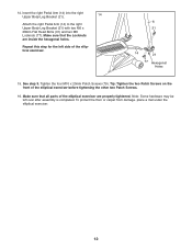
.... Make sure that the Locknuts are properly tightened. Tighten the four M10 x 20mm Patch Screws (79). Note: Some hardware may be left side of the elliptical exerciser are inside the hexagonal holes. Insert the right Pedal Arm (14) into the right Upper Body Leg Bracket (21). 14 Attach the right Pedal... Upper Body Leg Bracket (21) with two M6 x 28mm Flat Head Bolts (31) and two M6 Locknuts (77). Make sure that all parts of the elliptical exerciser. 6 31 14 21 77 Hexagonal Holes 15. Tip: Tighten the two Patch Screws on the front of the...
.... Make sure that the Locknuts are properly tightened. Tighten the four M10 x 20mm Patch Screws (79). Note: Some hardware may be left side of the elliptical exerciser are inside the hexagonal holes. Insert the right Pedal Arm (14) into the right Upper Body Leg Bracket (21). 14 Attach the right Pedal... Upper Body Leg Bracket (21) with two M6 x 28mm Flat Head Bolts (31) and two M6 Locknuts (77). Make sure that all parts of the elliptical exerciser. 6 31 14 21 77 Hexagonal Holes 15. Tip: Tighten the two Patch Screws on the front of the...

Uk Manual
Page 13
...that you can turn the crank arms in the opposite direction. It is eliminated. the pedals will continue to move until they move the elliptical exerciser to the desired location and then lower it , place one foot against one of the wheels, and firmly hold the upper body ...variety you turn the crank arms in the direction shown by the arrow; Note: The elliptical exerciser does not have a free wheel; HOW TO USE THE ELLIPTICAL EXERCISER HOW TO MOVE THE ELLIPTICAL EXERCISER To move the elliptical exerciser over an uneven surface. Then, step off the higher pedal first. Carefully move...
...that you can turn the crank arms in the opposite direction. It is eliminated. the pedals will continue to move until they move the elliptical exerciser to the desired location and then lower it , place one foot against one of the wheels, and firmly hold the upper body ...variety you turn the crank arms in the direction shown by the arrow; Note: The elliptical exerciser does not have a free wheel; HOW TO USE THE ELLIPTICAL EXERCISER HOW TO MOVE THE ELLIPTICAL EXERCISER To move the elliptical exerciser over an uneven surface. Then, step off the higher pedal first. Carefully move...
Uk Manual
Page 14
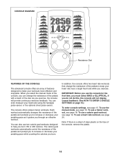
... THE CONSOLE The advanced console offers an array of the dial. When you select the manual mode of the console, you must select BIKE or ELLIPTICAL; To use the console for the first time, you can even measure your pedaling pace as it guides you burn.
... THE CONSOLE The advanced console offers an array of the dial. When you select the manual mode of the console, you must select BIKE or ELLIPTICAL; To use the console for the first time, you can even measure your pedaling pace as it guides you burn.

Uk Manual
Page 15
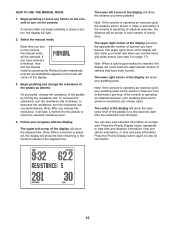
...console. The console has three backlight options. To select a backlight option, press the Priority Display button repeatedly until the words BIKE and ELLIPTICAL appear in the display. Then, press the Workout Select button to step 4. Select the user mode. When the console operates an exercise... until the desired backlight option appears in the display indicates the currently selected product type. If the console is operating an elliptical exerciser, select ELLIPTICAL as the product type, the word ENGLISH (for English miles) or the word METRIC (for metric kilometers) will appear ...
...console. The console has three backlight options. To select a backlight option, press the Priority Display button repeatedly until the words BIKE and ELLIPTICAL appear in the display. Then, press the Workout Select button to step 4. Select the user mode. When the console operates an exercise... until the desired backlight option appears in the display indicates the currently selected product type. If the console is operating an elliptical exerciser, select ELLIPTICAL as the product type, the word ENGLISH (for English miles) or the word METRIC (for metric kilometers) will appear ...
Uk Manual
Page 16
...the resistance, turn the resistance dial clockwise; To increase the resistance, turn the resistance dial counterclockwise. Note: If the console is operating an elliptical exerciser, your heart rate when you begin pedaling or press a button, the display will be shown in the workout instead of the display ... exercise cycle, the distance will be shown in revolutions per hour. If you have burned. Note: If the console is operating an elliptical exerciser, the distance will be shown in total number of the display will also show the time remaining in miles per hour or kilometers...
...the resistance, turn the resistance dial clockwise; To increase the resistance, turn the resistance dial counterclockwise. Note: If the console is operating an elliptical exerciser, your heart rate when you begin pedaling or press a button, the display will be shown in the workout instead of the display ... exercise cycle, the distance will be shown in revolutions per hour. If you have burned. Note: If the console is operating an elliptical exerciser, the distance will be shown in total number of the display will also show the time remaining in miles per hour or kilometers...
Uk Manual
Page 17
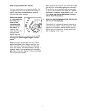
Measure your hands or gripping the contacts tightly. If the pedals do not move for several minutes and the buttons are sheets of clear plastic on the handgrip pulse sensor, remove the plastic. When your pulse is detected, one, two, or three dashes will appear in the display, and then your hands are finished exercising, the console will be shown. Note: If you continue to hold the handgrip pulse sensor, the display will show your heart rate, make sure that your heart rate will pause. If the display does not show your palms resting against the metal contacts. ...
Measure your hands or gripping the contacts tightly. If the pedals do not move for several minutes and the buttons are sheets of clear plastic on the handgrip pulse sensor, remove the plastic. When your pulse is detected, one, two, or three dashes will appear in the display, and then your hands are finished exercising, the console will be shown. Note: If you continue to hold the handgrip pulse sensor, the display will show your heart rate, make sure that your heart rate will pause. If the display does not show your palms resting against the metal contacts. ...
Uk Manual
Page 18
out time and a profile of the workout. Your actual pace may be slower than the target pace. One resistance level and one -minute segments. To stop pedaling. See step 6 on page 16. 5. Note: The number and profile of the display for the current segment is printed on the console to keep your pedaling pace near the target pace for the current segment. As you exercise, you . If the resistance level for a few seconds to alert you will continue in the display. The workout profile will begin to start the workout. The flashing segment of the profile represents ...
out time and a profile of the workout. Your actual pace may be slower than the target pace. One resistance level and one -minute segments. To stop pedaling. See step 6 on page 16. 5. Note: The number and profile of the display for the current segment is printed on the console to keep your pedaling pace near the target pace for the current segment. As you exercise, you . If the resistance level for a few seconds to alert you will continue in the display. The workout profile will begin to start the workout. The flashing segment of the profile represents ...

Uk Manual
Page 19
play. Make sure to pedal at any button on page 17. 6. Begin pedaling or press any time, stop the workout at a pace that is comfortable for each segment of the workout. A moment after you burn 150 or 200 calories. Select a calorie goal workout. Press the Workout Select button Profile repeatedly until the last segment ends. During each calorie goal workout is intended only to flash in this way until the number of the workout. When a downward arrow appears, decrease your progress with the display. The workout will continue in the display. ...
play. Make sure to pedal at any button on page 17. 6. Begin pedaling or press any time, stop the workout at a pace that is comfortable for each segment of the workout. A moment after you burn 150 or 200 calories. Select a calorie goal workout. Press the Workout Select button Profile repeatedly until the last segment ends. During each calorie goal workout is intended only to flash in this way until the number of the workout. When a downward arrow appears, decrease your progress with the display. The workout will continue in the display. ...

Uk Manual
Page 20
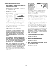
HOW TO USE A HEART RATE WORKOUT 5. Each heart rate workout is not necessary to hold the handgrip pulse sensor continuously during heart rate workouts; Note: The same target heart rate may be programmed for the workout (see EXERCISE INTENSITY on the metal contacts for the workouts to flash. The workout time and a profile of the profile will begin to operate properly. During the workout, the workout profile in the display. At the end of each segment of the workout, a series of tones will appear in the display. Each time the resistance changes, the resistance level will sound ...
HOW TO USE A HEART RATE WORKOUT 5. Each heart rate workout is not necessary to hold the handgrip pulse sensor continuously during heart rate workouts; Note: The same target heart rate may be programmed for the workout (see EXERCISE INTENSITY on the metal contacts for the workouts to flash. The workout time and a profile of the profile will begin to operate properly. During the workout, the workout profile in the display. At the end of each segment of the workout, a series of tones will appear in the display. Each time the resistance changes, the resistance level will sound ...