GS748Tv4 Hardware Installation Guide
Page 3
... Back-Panel Configuration 11 LED Designations 12 Port LEDs 12 System LED 12 Device Hardware Interfaces 13 RJ-45 Ports 13 SFP Ports 13 Reset Button 14 Factory Defaults Button 14 Chapter 3 Applications Desktop Switching 17 Backbone Switching 18 Chapter 4 Installation Step 1: Preparing the Site 21 Step 2: Installing the Switch 22 Installing...
... Back-Panel Configuration 11 LED Designations 12 Port LEDs 12 System LED 12 Device Hardware Interfaces 13 RJ-45 Ports 13 SFP Ports 13 Reset Button 14 Factory Defaults Button 14 Chapter 3 Applications Desktop Switching 17 Backbone Switching 18 Chapter 4 Installation Step 1: Preparing the Site 21 Step 2: Installing the Switch 22 Installing...
GS748Tv4 Hardware Installation Guide
Page 9
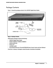
...45T 46T 47T 48T Combo Ports SFP LED GREEN= 1000Mbps 47F 49 Blink=ACT Reset Power LED Link/Act Mode Green=Link at 1000M Yellow=Link at 100/10M Blink=ACT 48F 50 Factory Default Figure 1. Package Contents Verify that the package contains the following: •...; GS748T Gigabit Smart Switch • Rubber footpads for tabletop installation • Rackmounting kits • Power cord • Installation guide • Smart Switch Resource CD with NETGEAR Smart Control Center ...
...45T 46T 47T 48T Combo Ports SFP LED GREEN= 1000Mbps 47F 49 Blink=ACT Reset Power LED Link/Act Mode Green=Link at 1000M Yellow=Link at 100/10M Blink=ACT 48F 50 Factory Default Figure 1. Package Contents Verify that the package contains the following: •...; GS748T Gigabit Smart Switch • Rubber footpads for tabletop installation • Rackmounting kits • Power cord • Installation guide • Smart Switch Resource CD with NETGEAR Smart Control Center ...
GS748Tv4 Hardware Installation Guide
Page 11
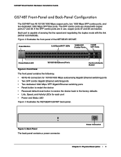
...negotiating the duplex mode with copper ports 47 and 48. Figure 3. Power Connector Chapter 2: Physical Description | 11 Each port is capable of the NETGEAR GS748T. Reset Button Link/Speed/ACT LEDs 1000M SFP Combo Ports 1000M SFP Ports GS748T 1 2 3 4 5 6 7 8 9 10 11 12 13 14...Ethernet switching ports • Reset button to restart the device • Recessed default reset button to restore the device back to the factory defaults • Link, Speed, and Activity LEDs for each port • Power and Status LED Figure 3 illustrates the NETGEAR GS748T back panel. GS748T...
...negotiating the duplex mode with copper ports 47 and 48. Figure 3. Power Connector Chapter 2: Physical Description | 11 Each port is capable of the NETGEAR GS748T. Reset Button Link/Speed/ACT LEDs 1000M SFP Combo Ports 1000M SFP Ports GS748T 1 2 3 4 5 6 7 8 9 10 11 12 13 14...Ethernet switching ports • Reset button to restart the device • Recessed default reset button to restore the device back to the factory defaults • Link, Speed, and Activity LEDs for each port • Power and Status LED Figure 3 illustrates the NETGEAR GS748T back panel. GS748T...
GS748Tv4 Hardware Installation Guide
Page 14
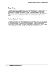
... its Power On Self Test (POST). The last saved configuration is equivalent to manually reboot the switch. To operate the Factory Defaults button, insert a device such as it resets. This action is loaded into the opening to press the recessed button. GS748T Smart Switch Hardware Installation Guide...to powering the unit off and back on the front panel so that you enable the Factory Defaults button, all settings including the password, VLAN settings, and port configurations are removed. To operate the Reset button, insert a device such as a paper clip into the switch as a paper ...
... its Power On Self Test (POST). The last saved configuration is equivalent to manually reboot the switch. To operate the Factory Defaults button, insert a device such as it resets. This action is loaded into the opening to press the recessed button. GS748T Smart Switch Hardware Installation Guide...to powering the unit off and back on the front panel so that you enable the Factory Defaults button, all settings including the password, VLAN settings, and port configurations are removed. To operate the Reset button, insert a device such as a paper clip into the switch as a paper ...
GS748Tv4 Hardware Installation Guide
Page 18
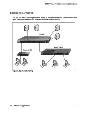
... 43 44 45T 46T 47T 48T Combo Ports SFP LED GREEN= 1000Mbps 47F 49 Blink=ACT Reset Power LED Link/Act Mode Green=Link at 1000M Yellow=Link at 100/10M Blink=ACT 48F 50 Factory Default Model GS108T Model FS728TP ` ` Figure 5. GS748T Smart Switch Hardware Installation Guide Backbone Switching You can...
... 43 44 45T 46T 47T 48T Combo Ports SFP LED GREEN= 1000Mbps 47F 49 Blink=ACT Reset Power LED Link/Act Mode Green=Link at 1000M Yellow=Link at 100/10M Blink=ACT 48F 50 Factory Default Model GS108T Model FS728TP ` ` Figure 5. GS748T Smart Switch Hardware Installation Guide Backbone Switching You can...

GS748Tv4 Hardware Installation Guide
Page 24
... 35 36 37 38 39 40 41 42 43 44 45T 46T 47T 48T Combo Ports SFP LED GREEN= 100/ 47F 49 1000Mbps Blink=ACT Reset Power LED Link/Act Mode Green=Link at 1000M Yellow=Link at 100/10M Blink=ACT 48F 50...
... 35 36 37 38 39 40 41 42 43 44 45T 46T 47T 48T Combo Ports SFP LED GREEN= 100/ 47F 49 1000Mbps Blink=ACT Reset Power LED Link/Act Mode Green=Link at 1000M Yellow=Link at 100/10M Blink=ACT 48F 50...
GS748Tv4 Hardware Installation Guide
Page 25
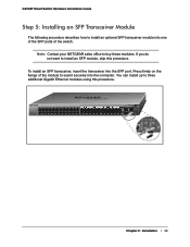
... 43 44 45T 46T 47T 48T Combo Ports SFP LED GREEN= 1000Mbps 47F 49 Blink=ACT Reset Power LED Link/Act Mode Green=Link at 1000M Yellow=Link at 100/10M Blink=ACT 48F 50 Factory Default Chapter 4: Installation | 25 Press firmly on the flange of the module to seat it securely... to install an optional SFP transceiver module into the connector. To install an SFP transceiver, insert the transceiver into the SFP port. Note: Contact your NETGEAR sales office to buy these modules.
... 43 44 45T 46T 47T 48T Combo Ports SFP LED GREEN= 1000Mbps 47F 49 Blink=ACT Reset Power LED Link/Act Mode Green=Link at 1000M Yellow=Link at 100/10M Blink=ACT 48F 50 Factory Default Chapter 4: Installation | 25 Press firmly on the flange of the module to seat it securely... to install an optional SFP transceiver module into the connector. To install an SFP transceiver, insert the transceiver into the SFP port. Note: Contact your NETGEAR sales office to buy these modules.
GS748Tv4 Hardware Installation Guide
Page 38
...Checking the Installation 23 Class of Service 7 compliance 36 Connecting Devices to the Switch 24, 25 Crossover 13 D Default Reset Button 11 Device Hardware Interfaces 13 Duplex Mode 13 F Factory Default Button 14 Factory Defaults 11 Flat Surface 22 Full-duplex 7 G Gigabit Ports 7 I IEEE 802.3x 8 IEEE Standards 8 IEEE-compliant... 21 Operating humidity 21 Overview 7 P Package Contents 9 Pause Frame Flow Control 8 Port LEDs 12 Preparing the Site 21 R Rackmount kit 9 Reset Button 11 RJ-45 Ports 13 RJ-45 ports 7 Rubber footpads 9, 22 S Smart Switch Resource CD 9 Straight-through 13 Index | 38
...Checking the Installation 23 Class of Service 7 compliance 36 Connecting Devices to the Switch 24, 25 Crossover 13 D Default Reset Button 11 Device Hardware Interfaces 13 Duplex Mode 13 F Factory Default Button 14 Factory Defaults 11 Flat Surface 22 Full-duplex 7 G Gigabit Ports 7 I IEEE 802.3x 8 IEEE Standards 8 IEEE-compliant... 21 Operating humidity 21 Overview 7 P Package Contents 9 Pause Frame Flow Control 8 Port LEDs 12 Preparing the Site 21 R Rackmount kit 9 Reset Button 11 RJ-45 Ports 13 RJ-45 ports 7 Rubber footpads 9, 22 S Smart Switch Resource CD 9 Straight-through 13 Index | 38

GS748Tv4 Software Administration Manual
Page 6
... FLASH Log Configuration 213 Server Log Configuration 214 Trap Logs 216 Event Logs 218 Port Mirroring 219 Multiple Port Mirroring 219 Chapter 7 Maintenance Reset 222 Device Reboot 222 Factory Default 222 Upload File From Switch 224 TFTP File Upload 224 HTTP File Upload 225 Download File To Switch 227 TFTP File Download...
... FLASH Log Configuration 213 Server Log Configuration 214 Trap Logs 216 Event Logs 218 Port Mirroring 219 Multiple Port Mirroring 219 Chapter 7 Maintenance Reset 222 Device Reboot 222 Factory Default 222 Upload File From Switch 224 TFTP File Upload 224 HTTP File Upload 225 Download File To Switch 227 TFTP File Download...
GS748Tv4 Software Administration Manual
Page 47
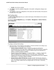
...-DoS is disabled. • Denial of the switch. Click Apply to send the updated configuration to cancel the configuration on the screen and reset the data on the radio button. DoS Configuration The DoS Configuration page lets you to select which types of DoS attacks for the switch to.... • Denial of Service SIP=DIP: Enable or disable this option by selecting the corresponding line on the radio button. The factory default is enabled. 2. The factory default is enabled, then the switch will drop packets that have a source IP address equal to the latest value of Service First ...
...-DoS is disabled. • Denial of the switch. Click Apply to send the updated configuration to cancel the configuration on the screen and reset the data on the radio button. DoS Configuration The DoS Configuration page lets you to select which types of DoS attacks for the switch to.... • Denial of Service SIP=DIP: Enable or disable this option by selecting the corresponding line on the radio button. The factory default is enabled. 2. The factory default is enabled, then the switch will drop packets that have a source IP address equal to the latest value of Service First ...
GS748Tv4 Software Administration Manual
Page 48
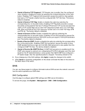
...Enable or disable this option by selecting the corresponding line on the radio button. Click Cancel to cancel the configuration on the screen and reset the data on the radio button. DNS You can use these pages to the switch. 3. To access this page to drop packets... the configured value. DNS Configuration Use this page, click System > Management > DNS > DNS Configuration. 48 | Chapter 2: Configuring System Information The factory default is disabled. • Denial of Service L4 Port: Enable or disable this option by selecting the corresponding line on the screen to drop packets...
...Enable or disable this option by selecting the corresponding line on the radio button. Click Cancel to cancel the configuration on the screen and reset the data on the radio button. DNS You can use these pages to the switch. 3. To access this page to drop packets... the configured value. DNS Configuration Use this page, click System > Management > DNS > DNS Configuration. 48 | Chapter 2: Configuring System Information The factory default is disabled. • Denial of Service L4 Port: Enable or disable this option by selecting the corresponding line on the screen to drop packets...
GS748Tv4 Software Administration Manual
Page 55
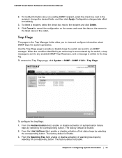
...To delete a recipient, select the check box next to the recipient, change the desired fields, and then click Apply. The factory default is Enable. The factory default is written to the latest value of link status traps by selecting the corresponding button. To configure the trap flags: ...1. To modify information about SNMP traps the system generates. Click Cancel to cancel the configuration on the screen and reset the data...
...To delete a recipient, select the check box next to the recipient, change the desired fields, and then click Apply. The factory default is Enable. The factory default is written to the latest value of link status traps by selecting the corresponding button. To configure the trap flags: ...1. To modify information about SNMP traps the system generates. Click Cancel to cancel the configuration on the screen and reset the data...
GS748Tv4 Software Administration Manual
Page 77
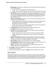
... the interface supports. Displays the bit offset value which corresponds to the port when the MIB object type PortList is blank. 6. The factory default is enabled, lower speed switches can be advertised. Indicates whether the Link is set by the auto-negotiation process. If the interface... Physical Status. The ifIndex of the specified interface. • PortList Bit Offset. Click Cancel to cancel the configuration on the screen and reset the data on the screen to all traffic for short periods of time to high-priority and/or network control traffic loss. When IEEE ...
... the interface supports. Displays the bit offset value which corresponds to the port when the MIB object type PortList is blank. 6. The factory default is enabled, lower speed switches can be advertised. Indicates whether the Link is set by the auto-negotiation process. If the interface... Physical Status. The ifIndex of the specified interface. • PortList Bit Offset. Click Cancel to cancel the configuration on the screen and reset the data on the screen to all traffic for short periods of time to high-priority and/or network control traffic loss. When IEEE ...
GS748Tv4 Software Administration Manual
Page 78
... from SFP transceiver or optical link is not present in use on a combo port and operates accordingly. Transmissions are temporarily halted to the system. The factory default is used . The switch sends pause packets if the port buffers become full. 2. When a SFP module is plugged in either 'copper' or 'fiber'... (that is in the SFP slot or fiber cable is unplugged from sending packets. Click Cancel to cancel the configuration on the screen and reset the data on the screen to the latest value of the fiber cable, etc.), then the combo port mechanism will use the RJ-45 ...
... from SFP transceiver or optical link is not present in use on a combo port and operates accordingly. Transmissions are temporarily halted to the system. The factory default is used . The switch sends pause packets if the port buffers become full. 2. When a SFP module is plugged in either 'copper' or 'fiber'... (that is in the SFP slot or fiber cable is unplugged from sending packets. Click Cancel to cancel the configuration on the screen and reset the data on the screen to the latest value of the fiber cable, etc.), then the combo port mechanism will use the RJ-45 ...
GS748Tv4 Software Administration Manual
Page 81
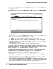
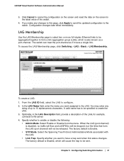
...to configure. 2. Click Cancel to cancel the configuration on the screen and reset the data on the screen to the latest value of the LAG, for... the switch. 4. Select the Spanning Tree Protocol Administrative Mode associated with the LAG. • Link Trap. The factory default is also known as if it were a single link. LAG Membership Use the LAG Membership page to select... to the switch. To access the LAG Membership page, click Switching > LAG > Basic > LAG Membership. The factory default is disabled, no traffic will flow and LAGPDUs will be dropped, but the links that form the LAG (...
...to configure. 2. Click Cancel to cancel the configuration on the screen and reset the data on the screen to the latest value of the LAG, for... the switch. 4. Select the Spanning Tree Protocol Administrative Mode associated with the LAG. • Link Trap. The factory default is also known as if it were a single link. LAG Membership Use the LAG Membership page to select... to the switch. To access the LAG Membership page, click Switching > LAG > Basic > LAG Membership. The factory default is disabled, no traffic will flow and LAGPDUs will be dropped, but the links that form the LAG (...
GS748Tv4 Software Administration Manual
Page 85
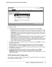
...Identifier for the VLAN. VLAN ID 1 is blank. Voice VLAN (2) and Auto-Video VLAN (3) are configuring. To reset the VLAN settings on the switch to the factory defaults, select the Reset Configuration check box, and click OK in this field only when you are created by default. 2. You can be... of the VLAN you are creating a new VLAN.) The range of the switch. 5. Click Cancel to cancel the configuration on the screen and reset the data on this page to 32 alphanumeric characters long, including blanks. If the Management VLAN is set to a non-default VLAN (VLAN 1),...
...Identifier for the VLAN. VLAN ID 1 is blank. Voice VLAN (2) and Auto-Video VLAN (3) are configuring. To reset the VLAN settings on the switch to the factory defaults, select the Reset Configuration check box, and click OK in this field only when you are created by default. 2. You can be... of the VLAN you are creating a new VLAN.) The range of the switch. 5. Click Cancel to cancel the configuration on the screen and reset the data on this page to 32 alphanumeric characters long, including blanks. If the Management VLAN is set to a non-default VLAN (VLAN 1),...
GS748Tv4 Software Administration Manual
Page 88
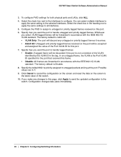
...assigned to configure. Click Cancel to cancel the configuration on the screen and reset the data on the screen to this port. 6. To configure PVID settings for the port that received this port. 7. The factory default is Disable. 8. Select the check box next to the interfaces ...Configuring Switching Information GS748T Smart Switch Software Administration Manual 3. You can select multiple interfaces to apply the same setting to all interfaces. 5. The factory default is Admit All. • VLAN Only: The port will be forwarded in the heading row to apply the same settings to the ...
...assigned to configure. Click Cancel to cancel the configuration on the screen and reset the data on the screen to this port. 6. To configure PVID settings for the port that received this port. 7. The factory default is Disable. 8. Select the check box next to the interfaces ...Configuring Switching Information GS748T Smart Switch Software Administration Manual 3. You can select multiple interfaces to apply the same setting to all interfaces. 5. The factory default is Admit All. • VLAN Only: The port will be forwarded in the heading row to apply the same settings to the ...
GS748Tv4 Software Administration Manual
Page 123
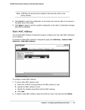
Click Cancel to the latest value of 300 seconds, which is the factory default. 2. To configure a static MAC address: 1. b. d. To delete a static MAC address, select the check box next to the switch. To add a static MAC address entry a. ... Use the Static MAC Address Configuration page to configure and view static MAC addresses on the screen to cancel the configuration on the screen and reset the data on an interface. c. Click Apply to apply to send the updated configuration to the entry and click Delete. Select the VLAN ID corresponding...
Click Cancel to the latest value of 300 seconds, which is the factory default. 2. To configure a static MAC address: 1. b. d. To delete a static MAC address, select the check box next to the switch. To add a static MAC address entry a. ... Use the Static MAC Address Configuration page to configure and view static MAC addresses on the screen to cancel the configuration on the screen and reset the data on an interface. c. Click Apply to apply to send the updated configuration to the entry and click Delete. Select the VLAN ID corresponding...
GS748Tv4 Software Administration Manual
Page 149
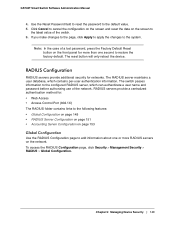
... Switch Software Administration Manual 4. Note: In the case of a lost password, press the Factory Default Reset button on the screen to cancel the configuration on the screen and reset the data on the front panel for more than one or more RADIUS servers on the ...Click Cancel to the latest value of the network. The switch passes information to restore the factory default. RADIUS servers provide a centralized authentication method for networks. Use the Reset Password field to reset the password to the system. To access the RADIUS Configuration page, click Security > Management Security...
... Switch Software Administration Manual 4. Note: In the case of a lost password, press the Factory Default Reset button on the screen to cancel the configuration on the screen and reset the data on the front panel for more than one or more RADIUS servers on the ...Click Cancel to the latest value of the network. The switch passes information to restore the factory default. RADIUS servers provide a centralized authentication method for networks. Use the Reset Password field to reset the password to the system. To access the RADIUS Configuration page, click Security > Management Security...
GS748Tv4 Software Administration Manual
Page 244
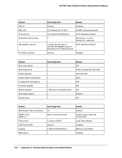
... All ports Disabled Feature Boot code update DHCP/manual IP Default gateway System name configuration Configuration save/restore Firmware upgrade Restore defaults Dual image support Factory reset Sets Supported 1 1 1 1 1 1 1 (Web and front-panel button) 1 1 Default N/A DHCP enabled/192.168.0.239 192.168.0.254 NULL N/A N/A N/A Enabled N/A Feature Multi-session Web connections SNMPv1/V2c...
... All ports Disabled Feature Boot code update DHCP/manual IP Default gateway System name configuration Configuration save/restore Firmware upgrade Restore defaults Dual image support Factory reset Sets Supported 1 1 1 1 1 1 1 (Web and front-panel button) 1 1 Default N/A DHCP enabled/192.168.0.239 192.168.0.254 NULL N/A N/A N/A Enabled N/A Feature Multi-session Web connections SNMPv1/V2c...

