
FS752TS Setup Manual
Page 10
... help and support. • Appendix A, "Default Settings" gives FS700TS Smart Switch specifications and lists default feature values. FS700TS Smart Switch Software Administration Manual • Chapter 6, "Managing Security" describes how to configure security. • Chapter 7, "Monitoring the Switch" describes how to configure switch monitoring. • Chapter 8, "Maintenance" describes...: Italics Bold Fixed italics Emphasis, books, CDs, file and server names, extensions User input, IP addresses, GUI screen text Command prompt, CLI text, code URL links • Formats.
... help and support. • Appendix A, "Default Settings" gives FS700TS Smart Switch specifications and lists default feature values. FS700TS Smart Switch Software Administration Manual • Chapter 6, "Managing Security" describes how to configure security. • Chapter 7, "Monitoring the Switch" describes how to configure switch monitoring. • Chapter 8, "Maintenance" describes...: Italics Bold Fixed italics Emphasis, books, CDs, file and server names, extensions User input, IP addresses, GUI screen text Command prompt, CLI text, code URL links • Formats.
FS752TS Setup Manual
Page 17
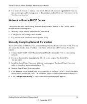
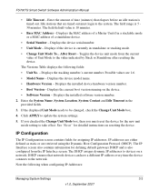
Proceed as follows: 1. Connect the FS700TS 10/100 Stackable Smart Switch with Gigabit Ports. Install the SmartWizard Discovery utility on the switch installation CD. 4. A screen similar to that shown in Figure 1-1. 6. You can also assign the switch a static IP address even if your computer. The default IP is located on your network has DHCP service. The SmartWizard Discovery utility...
Proceed as follows: 1. Connect the FS700TS 10/100 Stackable Smart Switch with Gigabit Ports. Install the SmartWizard Discovery utility on the switch installation CD. 4. A screen similar to that shown in Figure 1-1. 6. You can also assign the switch a static IP address even if your computer. The default IP is located on your network has DHCP service. The SmartWizard Discovery utility...
FS752TS Setup Manual
Page 18
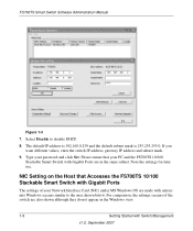
... subnet mask. 9. Note the settings for later use. For comparison, the settings screens of your password and click Set. FS700TS Smart Switch Software Administration Manual . The default IP address is 192.168.0.239 and the default subnet mask is 255.255.255.0. Type your Network Interface Card (NIC) under MS Windows OS are also shown although...
... subnet mask. 9. Note the settings for later use. For comparison, the settings screens of your password and click Set. FS700TS Smart Switch Software Administration Manual . The default IP address is 192.168.0.239 and the default subnet mask is 255.255.255.0. Type your Network Interface Card (NIC) under MS Windows OS are also shown although...
FS752TS Setup Manual
Page 20
... be set up IP address and subnet mask, either with an "out of the box" switch and are starting with or without DHCP server, use that contains the switch (i.e., the subnet mask values of switch and PC host must be on a network segment to match the default parameters of the switch covered in your browser using the switch IP address.
... be set up IP address and subnet mask, either with an "out of the box" switch and are starting with or without DHCP server, use that contains the switch (i.e., the subnet mask values of switch and PC host must be on a network segment to match the default parameters of the switch covered in your browser using the switch IP address.
FS752TS Setup Manual
Page 37
...configured from the current value of a standalone device. • Serial Number - The DHCP assigns dynamic IP addresses to update the system settings. 5. The field default value is 5 30 minutes. After Reset - Possible values are retrieved using the Dynamic Host Configuration ...IP Interface screen. Displays the installed device hardware version number. • Boot Version - Enter the amount of a Master Unit if in the provided fields. 3. Idle stations that are timed out must reset the device for detailed instructions on the device. • Software Version - FS700TS Smart Switch...
...configured from the current value of a standalone device. • Serial Number - The DHCP assigns dynamic IP addresses to update the system settings. 5. The field default value is 5 30 minutes. After Reset - Possible values are retrieved using the Dynamic Host Configuration ...IP Interface screen. Displays the installed device hardware version number. • Boot Version - Enter the amount of a Master Unit if in the provided fields. 3. Idle stations that are timed out must reset the device for detailed instructions on the device. • Software Version - FS700TS Smart Switch...
FS752TS Setup Manual
Page 38
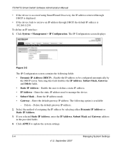
... fields. • Static IP Address - Delete the default gateway IP address. 2. To define an IP interface: 1. Enter the default gateway IP address. FS700TS Smart Switch Software Administration Manual • If the device is accessed using SmartWizard Discovery, the IP address retrieved through DHCP is displayed. • If the device fails to retrieve an IP address through DHCP, the default IP address is available: - Enter the IP address mask. • Gateway...
... fields. • Static IP Address - Delete the default gateway IP address. 2. To define an IP interface: 1. Enter the default gateway IP address. FS700TS Smart Switch Software Administration Manual • If the device is accessed using SmartWizard Discovery, the IP address retrieved through DHCP is displayed. • If the device fails to retrieve an IP address through DHCP, the default IP address is available: - Enter the IP address mask. • Gateway...
FS752TS Setup Manual
Page 59
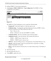
.... The default is 15 seconds. • Retries - Click APPLY to send notifications. Enter the IP address to which the traps are sent. - Traps are sent. • Notification Type - (Configurable only if the Notification Version is SNMPv2.) Select the type of time (in the first row. 4. Informs - Select the trap entry. 3. FS700TS Smart Switch Software Administration...
.... The default is 15 seconds. • Retries - Click APPLY to send notifications. Enter the IP address to which the traps are sent. - Traps are sent. • Notification Type - (Configurable only if the Notification Version is SNMPv2.) Select the type of time (in the first row. 4. Informs - Select the trap entry. 3. FS700TS Smart Switch Software Administration...
FS752TS Setup Manual
Page 72
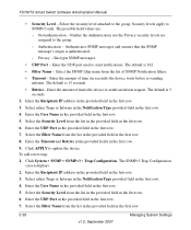
...) the device waits before re-sending informs. The default is 162. • Filter Name - To add a new trap: 1. Enter the Recipients IP address in the provided field in the first row. 5. NoAuthentication - Authentication - The default is authenticated. - Select the Security Level from the... Security levels apply to update the device. Enter the Recipients IP address in the provided field in the first row. 7. Enter the UDP Port in the provided field in the first row. 3. FS700TS Smart Switch Software Administration Manual • Security Level - The possible field...
...) the device waits before re-sending informs. The default is 162. • Filter Name - To add a new trap: 1. Enter the Recipients IP address in the provided field in the first row. 5. NoAuthentication - Authentication - The default is authenticated. - Select the Security Level from the... Security levels apply to update the device. Enter the Recipients IP address in the provided field in the first row. 7. Enter the UDP Port in the provided field in the first row. 3. FS700TS Smart Switch Software Administration Manual • Security Level - The possible field...
FS752TS Setup Manual
Page 131
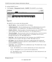
... Figure 6-2 The RADIUS screen contains the following fields: • Host IP Address - Possible field values are 1-30. Login - The authenticated port default is used for an answer from the RADIUS server before a failure occurs. The default value is 0. • Key String - The RADIUS server is 1812.... • Number of time (in seconds) the device waits for authenticating and encrypting all RADIUS-communications between the device and the RADIUS server. Enter the authentication port. FS700TS Smart Switch Software ...
... Figure 6-2 The RADIUS screen contains the following fields: • Host IP Address - Possible field values are 1-30. Login - The authenticated port default is used for an answer from the RADIUS server before a failure occurs. The default value is 0. • Key String - The RADIUS server is 1812.... • Number of time (in seconds) the device waits for authenticating and encrypting all RADIUS-communications between the device and the RADIUS server. Enter the authentication port. FS700TS Smart Switch Software ...
FS752TS Setup Manual
Page 132
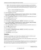
...the lists in the provided fields in the first row. 3. The system supports up-to update the device. FS700TS Smart Switch Software Administration Manual • Active - The system performs authentication initially with the Radius Primary Server, and if it fails... entry: 1. The default settings are applied to remove the entry. TACACS+ Terminal Access Controller Access Control System (TACACS+) provides centralized security user access validation. To add a new RADIUS server entry: 1. Defines the RADIUS Primary Server. - Enter the Host IP Address, Authentication Port, Number...
...the lists in the provided fields in the first row. 3. The system supports up-to update the device. FS700TS Smart Switch Software Administration Manual • Active - The system performs authentication initially with the Radius Primary Server, and if it fails... entry: 1. The default settings are applied to remove the entry. TACACS+ Terminal Access Controller Access Control System (TACACS+) provides centralized security user access validation. To add a new RADIUS server entry: 1. Defines the RADIUS Primary Server. - Enter the Host IP Address, Authentication Port, Number...
FS752TS Setup Manual
Page 133
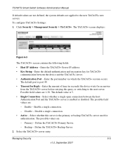
... used for an answer from the TACACS+ server before retrying the query, or switching to the new TACACS+ new servers. FS700TS Smart Switch Software Administration Manual If default values are not defined, the system defaults are : - Enter the amount of time (in seconds) the device waits ... • Single Connection - The TACACS+ screen displays: Figure 6-3 The TACACS+ screen contains the following fields: • Host IP Address - Define the TACACS+ Backup Server. 2. To configure TACACS+ Settings: 1. Enter the port number via which the TACACS+ session occurs. Primary - Backup ...
... used for an answer from the TACACS+ server before retrying the query, or switching to the new TACACS+ new servers. FS700TS Smart Switch Software Administration Manual If default values are not defined, the system defaults are : - Enter the amount of time (in seconds) the device waits ... • Single Connection - The TACACS+ screen displays: Figure 6-3 The TACACS+ screen contains the following fields: • Host IP Address - Define the TACACS+ Backup Server. 2. To configure TACACS+ Settings: 1. Enter the port number via which the TACACS+ session occurs. Primary - Backup ...

FS752TS Setup Manual
Page 157
...Smart Switch Software Administration Manual 2. The default value is Informational. All applications defined for viewing and configuring the remote log servers. Enter a user-defined server description. • Minimum Severity - The default value is 514. • Facility - If the device is down . The second highest warning level. Enter the server's IP address... to which system logs are sent to each server. Select an application from which logs can be defined and the log severity sent to the server. The field default is saved to the ...
...Smart Switch Software Administration Manual 2. The default value is Informational. All applications defined for viewing and configuring the remote log servers. Enter a user-defined server description. • Minimum Severity - The default value is 514. • Facility - If the device is down . The second highest warning level. Enter the server's IP address... to which system logs are sent to each server. Select an application from which logs can be defined and the log severity sent to the server. The field default is saved to the ...

FS752TS Setup Manual
Page 187
... up, 5-1 examples (VLANs), B-2 factory, 5-4 files, 5-1 LLDP, 3-15 logs, 3-25 network parameters, 1-5 port, 3-17, 4-1 resetting, 5-5 restoring, 5-3 spanning tree, 4-25 switch, 4-1 system settings, 3-1, 3-6 connectors, C-6 D defaults IP address, 1-7 subnet mask, 1-7 switch, A-2 DHCP server, 1-3 downloading files, 5-3 dynamic address, 3-12 E EAP, 4-36 F factory defaults, 5-4 factory reset, 5-4 Fast Ethernet cables, C-1 file download, 5-3 management, 5-1 upload, 5-1 flash logs, 3-27 G getting started, 1-1 H HTTP host, 5-1 I IEEE 802...
... up, 5-1 examples (VLANs), B-2 factory, 5-4 files, 5-1 LLDP, 3-15 logs, 3-25 network parameters, 1-5 port, 3-17, 4-1 resetting, 5-5 restoring, 5-3 spanning tree, 4-25 switch, 4-1 system settings, 3-1, 3-6 connectors, C-6 D defaults IP address, 1-7 subnet mask, 1-7 switch, A-2 DHCP server, 1-3 downloading files, 5-3 dynamic address, 3-12 E EAP, 4-36 F factory defaults, 5-4 factory reset, 5-4 Fast Ethernet cables, C-1 file download, 5-3 management, 5-1 upload, 5-1 flash logs, 3-27 G getting started, 1-1 H HTTP host, 5-1 I IEEE 802...
FS752TS Hardware manual
Page 21
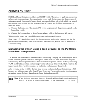
The default IP address is a default IP address already configured on the back of the switch. 2. The method of applying or removing AC power is by a wall switch, which results in correctly and that the power cable is plugged in the improvement of its ... using a Web Browser or the PC Utility for Initial Configuration The NETGEAR Smart Switch contains software for viewing, changing, and monitoring the way it works. Connect the 3-pronged end of the switch, which can configure the Smart Switch using a Web browser or a utility program called SmartWizard Discovery. However...
The default IP address is a default IP address already configured on the back of the switch. 2. The method of applying or removing AC power is by a wall switch, which results in correctly and that the power cable is plugged in the improvement of its ... using a Web Browser or the PC Utility for Initial Configuration The NETGEAR Smart Switch contains software for viewing, changing, and monitoring the way it works. Connect the 3-pronged end of the switch, which can configure the Smart Switch using a Web browser or a utility program called SmartWizard Discovery. However...
FS752TS Hardware manual
Page 36
... 1-2 Checking the Installation 4-15 Class of Service 1-2 Combo Port 2-10 Combo Ports 1-2 Connecting Devices to the Switch 4-16 Copper 1-1 Crossover 2-9 D Default IP Address 4-18 Default Reset Button 2-5, 2-7 Device Hardware Interfaces 2-9 Duplex Mode 2-9 E Example of Desktop Switching 3-12 F Factory Default Button 2-10 Factory Defaults 2-5 Fan LED 2-9 Fiber Connectivity 1-1 Flat Surface 4-14 Full-duplex 1-2 G GBIC 1-2, 2-10 Gigabit Ports 1-1 H High-speed...
... 1-2 Checking the Installation 4-15 Class of Service 1-2 Combo Port 2-10 Combo Ports 1-2 Connecting Devices to the Switch 4-16 Copper 1-1 Crossover 2-9 D Default IP Address 4-18 Default Reset Button 2-5, 2-7 Device Hardware Interfaces 2-9 Duplex Mode 2-9 E Example of Desktop Switching 3-12 F Factory Default Button 2-10 Factory Defaults 2-5 Fan LED 2-9 Fiber Connectivity 1-1 Flat Surface 4-14 Full-duplex 1-2 G GBIC 1-2, 2-10 Gigabit Ports 1-1 H High-speed...


