FS752TS Setup Manual
Page 5
...xii Revision History ...xii Chapter 1 Getting Started with Switch Management System Requirements ...1-1 Switch Management Interface 1-2 Network with a DHCP Server 1-3 Network... without a DHCP Server 1-5 Web Access ...1-7 Additional Utilities ...1-8 Chapter 2 Introduction to the Web Browser Interface Logging Into the NETGEAR Home Screen 2-1 Using the NETGEAR Web Management System Options 2-3 Chapter 3 Managing System Settings Using the System Settings Utility 3-1 Management ...3-1 Device View ...3-7 Stacking ...3-7 PoE...
...xii Revision History ...xii Chapter 1 Getting Started with Switch Management System Requirements ...1-1 Switch Management Interface 1-2 Network with a DHCP Server 1-3 Network... without a DHCP Server 1-5 Web Access ...1-7 Additional Utilities ...1-8 Chapter 2 Introduction to the Web Browser Interface Logging Into the NETGEAR Home Screen 2-1 Using the NETGEAR Web Management System Options 2-3 Chapter 3 Managing System Settings Using the System Settings Utility 3-1 Management ...3-1 Device View ...3-7 Stacking ...3-7 PoE...
FS752TS Setup Manual
Page 35
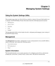
... and the system time, and contains the following main menu options: • "Management" • "Device View" • "Stacking" • "PoE" • "SNMP" The description that enables you to manage your FS700TSSmart Switch with features under the following options: • "System Information" • "IP Configuration" • "Time" System Information The System Information screen... menu enables configuration of the web browser interface contains a System tab that follows in this chapter describes configuring and managing system settings in the FS700TS Smart Switch.
... and the system time, and contains the following main menu options: • "Management" • "Device View" • "Stacking" • "PoE" • "SNMP" The description that enables you to manage your FS700TSSmart Switch with features under the following options: • "System Information" • "IP Configuration" • "Time" System Information The System Information screen... menu enables configuration of the web browser interface contains a System tab that follows in this chapter describes configuring and managing system settings in the FS700TS Smart Switch.
FS752TS Setup Manual
Page 50
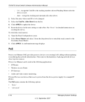
...be changed. 3. Reset the device for detailed instructions on resetting the device. A confirmation message displays. FS700TS Smart Switch Software Administration Manual - 1-6 - To switch the stack masters: 1. Power over existing LAN cabling without updating or modifying the network infrastructure. Auto - See...APPLY. This removes the limitation of placing network devices close to the stacking member selected Stacking Master after reboot. 2. PoE Power over Ethernet (PoE) provides power to be used in the following options: • "Basic" • "Advanced" 3-16 v1.0,...
...be changed. 3. Reset the device for detailed instructions on resetting the device. A confirmation message displays. FS700TS Smart Switch Software Administration Manual - 1-6 - To switch the stack masters: 1. Power over existing LAN cabling without updating or modifying the network infrastructure. Auto - See...APPLY. This removes the limitation of placing network devices close to the stacking member selected Stacking Master after reboot. 2. PoE Power over Ethernet (PoE) provides power to be used in the following options: • "Basic" • "Advanced" 3-16 v1.0,...
FS752TS Setup Manual
Page 51
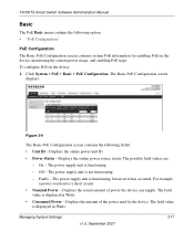
... circuit. • Nominal Power - The Basic PoE Configuration screen displays: Figure 3-9 The Basic PoE Configuration screen contains the following option: • "PoE Configuration" PoE Configuration The Basic PoE Configuration screen contains system PoE information for enabling PoE on the device: 1. Displays the actual amount ...Off - The power supply unit is not functioning. - The field value is displayed in Watts. FS700TS Smart Switch Software Administration Manual Basic The PoE Basic menu contains the following fields: • Unit ID - Displays the online power unit ID. ...
... circuit. • Nominal Power - The Basic PoE Configuration screen displays: Figure 3-9 The Basic PoE Configuration screen contains the following option: • "PoE Configuration" PoE Configuration The Basic PoE Configuration screen contains system PoE information for enabling PoE on the device: 1. Displays the actual amount ...Off - The power supply unit is not functioning. - The field value is displayed in Watts. FS700TS Smart Switch Software Administration Manual Basic The PoE Basic menu contains the following fields: • Unit ID - Displays the online power unit ID. ...
FS752TS Setup Manual
Page 52
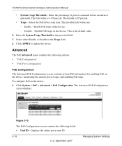
... menu contains the following fields: • Unit ID - Click APPLY to update the device. To configure PoE on the device, monitoring the current power usage, and enabling PoE traps. The possible field values are: - Disable - FS700TS Smart Switch Software Administration Manual • System Usage Threshold - Enable - Select either Enable or Disable in the provided...
... menu contains the following fields: • Unit ID - Click APPLY to update the device. To configure PoE on the device, monitoring the current power usage, and enabling PoE traps. The possible field values are: - Disable - FS700TS Smart Switch Software Administration Manual • System Usage Threshold - Enable - Select either Enable or Disable in the provided...
FS752TS Setup Manual
Page 53
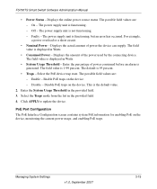
... power supply unit is displayed in Watts. • Consumed Power - The power supply unit is 1-99 percent. Faulty - Enable PoE traps on the device. Managing System Settings v1.0, September 2007 3-19 Disable - The possible field values are : - The field value... Threshold - Select the PoE device trap state. This is the default value. 2. PoE Port Configuration The PoE Interface Configuration screen contains system PoE information for enabling PoE on the device, monitoring the current power usage, and enabling PoE traps. FS700TS Smart Switch Software Administration Manual •...
... power supply unit is displayed in Watts. • Consumed Power - The power supply unit is 1-99 percent. Faulty - Enable PoE traps on the device. Managing System Settings v1.0, September 2007 3-19 Disable - The possible field values are : - The field value... Threshold - Select the PoE device trap state. This is the default value. 2. PoE Port Configuration The PoE Interface Configuration screen contains system PoE information for enabling PoE on the device, monitoring the current power usage, and enabling PoE traps. FS700TS Smart Switch Software Administration Manual •...
FS752TS Setup Manual
Page 54
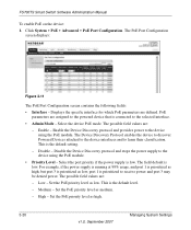
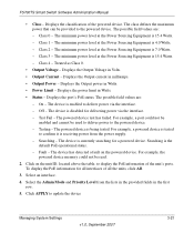
...Level - This is the default level. - Disable - Low - This is the default setting. - Set the PoE priority level as low. Click System > PoE > Advanced > PoE Port Configuration. PoE parameters are : - Enable the Device Discovery protocol and provides power to learn their classification. The field default is... prioritized as high, but port 3 is prioritized as high. 3-20 v1.0, September 2007 Managing System Settings FS700TS Smart Switch Software Administration Manual To enable PoE on the device: 1. Select the port priority if the power supply is connected to the device using the...
...Level - This is the default level. - Disable - Low - This is the default setting. - Set the PoE priority level as low. Click System > PoE > Advanced > PoE Port Configuration. PoE parameters are : - Enable the Device Discovery protocol and provides power to learn their classification. The field default is... prioritized as high, but port 3 is prioritized as high. 3-20 v1.0, September 2007 Managing System Settings FS700TS Smart Switch Software Administration Manual To enable PoE on the device: 1. Select the port priority if the power supply is connected to the device using the...
FS752TS Setup Manual
Page 55
... level at the Power Sourcing Equipment is 15.4 Watts. - Displays the port's PoE status. The device is 15.4 Watts. - For example, a port could not be provided to display the PoE information of the unit's ports. Click on the powered device. Click APPLY to ...in the provided fields in the first row. 5. To display the PoE information for a powered device. The class defines the maximum power that can be read. 2. Displays the Output power in Watts. • Status - Testing - FS700TS Smart Switch Software Administration Manual • Class - Class 0 - The possible...
... level at the Power Sourcing Equipment is 15.4 Watts. - Displays the port's PoE status. The device is 15.4 Watts. - For example, a port could not be provided to display the PoE information of the unit's ports. Click on the powered device. Click APPLY to ...in the provided fields in the first row. 5. To display the PoE information for a powered device. The class defines the maximum power that can be read. 2. Displays the Output power in Watts. • Status - Testing - FS700TS Smart Switch Software Administration Manual • Class - Class 0 - The possible...
FS752TS Hardware manual
Page 10
... BaseT, 2 ports of 10/100/1000 BaseT, and 2 GbE combo (Copper/Fiber) ports. • FS752TPS-PoE - This product offers support for use a device as an introduction to high-speed servers v1.0, September 2007 1-13 Chapter 1 Introduction The NETGEAR Smart Switch is a state-of-the-art, high-performance, IEEE-compliant network solution designed for 24 ports... the power of 192 10/100 ports or you can make high-speed connections using the Gigabit ports. This product offers support for the following NETGEAR FS700TS Smart Switches: • FS728TS - You can use out of the box.
... BaseT, 2 ports of 10/100/1000 BaseT, and 2 GbE combo (Copper/Fiber) ports. • FS752TPS-PoE - This product offers support for use a device as an introduction to high-speed servers v1.0, September 2007 1-13 Chapter 1 Introduction The NETGEAR Smart Switch is a state-of-the-art, high-performance, IEEE-compliant network solution designed for 24 ports... the power of 192 10/100 ports or you can make high-speed connections using the Gigabit ports. This product offers support for the following NETGEAR FS700TS Smart Switches: • FS728TS - You can use out of the box.
FS752TS Hardware manual
Page 24
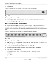
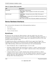
The device also offers 24-PoE enabled ports. Ports 25-48 are PoE ports. FS752TPS Front and Back Panels The NETGEAR FS752TPS Smart Switch is a standard AC power receptacle for accommodating the supplied power cord. On the FS752TPS, ports 1-24 are regular fast ports. • 4 RJ-45 ...back to the factory defaults. • Port LEDS • System LEDs 3-21 v1.0, September 2007 Physical Description Figure 3-5 illustrates the NETGEAR FS752TPS Smart Switch front panel: Figure 3-5 The front panel contains the following : • A 100-240VAC/50-60 Hz universal input, which is ...
The device also offers 24-PoE enabled ports. Ports 25-48 are PoE ports. FS752TPS Front and Back Panels The NETGEAR FS752TPS Smart Switch is a standard AC power receptacle for accommodating the supplied power cord. On the FS752TPS, ports 1-24 are regular fast ports. • 4 RJ-45 ...back to the factory defaults. • Port LEDS • System LEDs 3-21 v1.0, September 2007 Physical Description Figure 3-5 illustrates the NETGEAR FS752TPS Smart Switch front panel: Figure 3-5 The front panel contains the following : • A 100-240VAC/50-60 Hz universal input, which is ...
FS752TS Hardware manual
Page 26
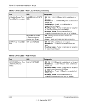
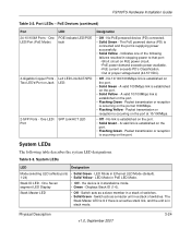
.... • Solid Green - Packet transmission or reception is established on the port. A valid 1000Mbps link is occurring on the port at 100Mbps. • Solid Yellow - PoE Devices Port LED 48-10/100M Ports - Table 3-2.
.... • Solid Green - Packet transmission or reception is established on the port. A valid 1000Mbps link is occurring on the port at 100Mbps. • Solid Yellow - PoE Devices Port LED 48-10/100M Ports - Table 3-2.
FS752TS Hardware manual
Page 27
... - System LEDs The following failures resulted in a stack of switches. Stack ID LED - One POE Indicate LED/POE LED/Port (PoE Mode) fault 4-Gigabits Copper Ports - A valid link is established on the port. • Flashing Green - Switch acts as a slave member in stopping power to that port:...v1.0, September 2007 3-24 the device is established on the port. Switch acts as a master unit in standalone mode. • Green - LED Mode in PoE LED Mode. A valid 10/100Mbps link is in a stack of switches. • Solid Green - No link is occurring on Jack LED...
... - System LEDs The following failures resulted in a stack of switches. Stack ID LED - One POE Indicate LED/POE LED/Port (PoE Mode) fault 4-Gigabits Copper Ports - A valid link is established on the port. • Flashing Green - Switch acts as a slave member in stopping power to that port:...v1.0, September 2007 3-24 the device is established on the port. Switch acts as a master unit in standalone mode. • Green - LED Mode in PoE LED Mode. A valid 10/100Mbps link is in a stack of switches. • Solid Green - No link is occurring on Jack LED...
FS752TS Hardware manual
Page 28
...the RJ-45 ports with an 8-pin RJ-45 plug. Indicates that the PoE MAX LED was active in the previous two minutes. • Off - When inserting a cable into the switch's RJ-45 port, the switch automatically: • Senses whether the cable is a straight-through or crossover ...cables. or full-duplex) of PoE power is disconnected. • Solid Green - All ports support only Unshielded Twisted-Pair...
...the RJ-45 ports with an 8-pin RJ-45 plug. Indicates that the PoE MAX LED was active in the previous two minutes. • Off - When inserting a cable into the switch's RJ-45 port, the switch automatically: • Senses whether the cable is a straight-through or crossover ...cables. or full-duplex) of PoE power is disconnected. • Solid Green - All ports support only Unshielded Twisted-Pair...
FS752TS Hardware manual
Page 37
... SFP GBIC Module 4-16 Installing the Switch 4-14 Internal Power Supply 1-3 L LED Designations 2-8 Link/ACT LED 2-8 Low Latency 1-2 M MAC 1-3 MAX POE LED 2-9 Media Access Control 1-3 Mounting Holes 4-14 N Nylon Washers 4-14 O ON/OFF switch 4-17 Operating Conditions 4-14 Operating Environment... SFP GBIC Module 2-10 SFP Link/ACT LED 2-8 SFP Module Bay 4-17 Site Requirements 4-13 Small Form-factor Pluggable (SFP) 1-2 Smart Switch Resource CD 1-4 SmartWizard Discovery 1-2 Straight-through 2-9 Support Information Card 1-4 System LEDs 2-9 T Temperature 4-14 Traffic Control 1-1 Troubleshooting Chart A-...
... SFP GBIC Module 4-16 Installing the Switch 4-14 Internal Power Supply 1-3 L LED Designations 2-8 Link/ACT LED 2-8 Low Latency 1-2 M MAC 1-3 MAX POE LED 2-9 Media Access Control 1-3 Mounting Holes 4-14 N Nylon Washers 4-14 O ON/OFF switch 4-17 Operating Conditions 4-14 Operating Environment... SFP GBIC Module 2-10 SFP Link/ACT LED 2-8 SFP Module Bay 4-17 Site Requirements 4-13 Small Form-factor Pluggable (SFP) 1-2 Smart Switch Resource CD 1-4 SmartWizard Discovery 1-2 Straight-through 2-9 Support Information Card 1-4 System LEDs 2-9 T Temperature 4-14 Traffic Control 1-1 Troubleshooting Chart A-...
