User's Guide
Page 108
... warranty period of Limited Warranty C780, C780n, C782, C782n printer Lexmark International, Inc. Extent of limited warranty Lexmark does not warrant uninterrupted or error-free operation of...Class I laser product conforming to this product for repair or replacement (at http://support.lexmark.com. Limited warranty Lexmark warrants that came with the product. To obtain...present for any human access to that is available are substantially used with Lexmark user's guides, manuals, instructions or guidance Unsuitable physical or operating environment Maintenance by : Modification...
... warranty period of Limited Warranty C780, C780n, C782, C782n printer Lexmark International, Inc. Extent of limited warranty Lexmark does not warrant uninterrupted or error-free operation of...Class I laser product conforming to this product for repair or replacement (at http://support.lexmark.com. Limited warranty Lexmark warrants that came with the product. To obtain...present for any human access to that is available are substantially used with Lexmark user's guides, manuals, instructions or guidance Unsuitable physical or operating environment Maintenance by : Modification...

Service Manual
Page 20
...provides additional information. CAUTION This type of caution indicates there is divided into the following chapters: 1. xx Service Manual Diagnostic information contains an error indicator table, symptom tables, and service checks used to isolate failing field replaceable units ...(FRUs). 3. Warning: A warning identifies something that might cause a servicer harm. Repair information provides instructions for making printer adjustments and removing and installing FRUs. 5. Appendix B contains representative print samples. Unplug...
...provides additional information. CAUTION This type of caution indicates there is divided into the following chapters: 1. xx Service Manual Diagnostic information contains an error indicator table, symptom tables, and service checks used to isolate failing field replaceable units ...(FRUs). 3. Warning: A warning identifies something that might cause a servicer harm. Repair information provides instructions for making printer adjustments and removing and installing FRUs. 5. Appendix B contains representative print samples. Unplug...
Service Manual
Page 43
...are not under the printer when you connect or disconnect any connections between the printer and PCs/peripherals. To determine the corrective action necessary to repair a printer, look for personal safety and to prevent damage to lift it safely. "Symptom table-HCIT 2000-sheet option" on page 2-5 ...the options before you lift or set the printer down. "1xx service errors" on page 2-9 - Contact your fingers are not contained in this service manual. "Symptom table-500-sheet drawer option" on page 2-11 - "Service checks" on page 2-14 Note: There may be found at least three ...
...are not under the printer when you connect or disconnect any connections between the printer and PCs/peripherals. To determine the corrective action necessary to repair a printer, look for personal safety and to prevent damage to lift it safely. "Symptom table-HCIT 2000-sheet option" on page 2-5 ...the options before you lift or set the printer down. "1xx service errors" on page 2-9 - Contact your fingers are not contained in this service manual. "Symptom table-500-sheet drawer option" on page 2-11 - "Service checks" on page 2-14 Note: There may be found at least three ...
Service Manual
Page 78
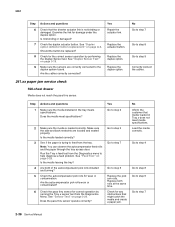
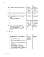
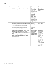
See "Duplex Sensor Test" on page A-3. Yes Repair the actuator link. Is the media loaded correctly? 3 See if the paper is trying to help diagnose a feed problem. Run the Tray x feed test from ... the Duplex Sensor test. Check the duplex actuator button. Replace the duplex option. No Go to step 7 Go to step 8 Go to step 7 2-36 Service Manual Make sure the side and back restraints are correctly connected to step 5 Replace the pick arm rolls. Load the media correctly. Is the media leaving...
See "Duplex Sensor Test" on page A-3. Yes Repair the actuator link. Is the media loaded correctly? 3 See if the paper is trying to help diagnose a feed problem. Run the Tray x feed test from ... the Duplex Sensor test. Check the duplex actuator button. Replace the duplex option. No Go to step 7 Go to step 8 Go to step 7 2-36 Service Manual Make sure the side and back restraints are correctly connected to step 5 Replace the pick arm rolls. Load the media correctly. Is the media leaving...
Service Manual
Page 82
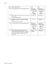
... in the tray. • No cotton content, or as little as necessary. Yes Replace the following FRUs in the tray meet specifications. Feed unit assembly. Repair or replace parts as possible to meet the user's needs. • If the envelopes have a pressure-sensitive adhesive flap, performance might be used in the... order shown: 1. Envelope feeder Before proceeding with this service check, make sure the envelope option is occurring? HCIT system board. Go to step 2 2-40 Service Manual HCIT system board. 2.
... in the tray. • No cotton content, or as little as necessary. Yes Replace the following FRUs in the tray meet specifications. Feed unit assembly. Repair or replace parts as possible to meet the user's needs. • If the envelopes have a pressure-sensitive adhesive flap, performance might be used in the... order shown: 1. Envelope feeder Before proceeding with this service check, make sure the envelope option is occurring? HCIT system board. Go to step 2 2-40 Service Manual HCIT system board. 2.
Service Manual
Page 86
... the following FRUs in the order shown: 1. HCIT system board. Registration sensor 2. HCIT system board. Replace the feed unit assembly. 2-44 Service Manual Does the LED flash 8 times? 12 Make sure the pick home sensor cable is occurring? No Replace the following FRUs in the order shown: ...board LED error code table" on page 2-84 to step 14 Install the cable correctly Replace the following FRUs in the order shown: 1. Repair or replace parts as necessary. HCIT system board. 2. Registration sensor. 2. Are you able to determine where the failure is installed correctly to...
... the following FRUs in the order shown: 1. HCIT system board. Registration sensor 2. HCIT system board. Replace the feed unit assembly. 2-44 Service Manual Does the LED flash 8 times? 12 Make sure the pick home sensor cable is occurring? No Replace the following FRUs in the order shown: ...board LED error code table" on page 2-84 to step 14 Install the cable correctly Replace the following FRUs in the order shown: 1. Repair or replace parts as necessary. HCIT system board. 2. Registration sensor. 2. Are you able to determine where the failure is installed correctly to...
Service Manual
Page 92
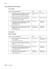
...board. Go to step 3 Go to step 4 Replace the control board. Is the flag operating correctly? Is the voltage correct? No Repair or replace as necessary. Reseat the cable. Bottom pass thru sensor-Make sure the sensor is correctly connected to J3 on the board. ...incomplete Step 1 2 3 4 Actions and questions Pass thru sensor flag-Check the sensor flag for correct operation. Replace the sensor assembly. 2-50 Service Manual Is there any problem found with the sensor flag? Replace the control board. Voltage check-Measure the voltage at J3-2. The voltage measures approximately 0 ...
...board. Go to step 3 Go to step 4 Replace the control board. Is the flag operating correctly? Is the voltage correct? No Repair or replace as necessary. Reseat the cable. Bottom pass thru sensor-Make sure the sensor is correctly connected to J3 on the board. ...incomplete Step 1 2 3 4 Actions and questions Pass thru sensor flag-Check the sensor flag for correct operation. Replace the sensor assembly. 2-50 Service Manual Is there any problem found with the sensor flag? Replace the control board. Voltage check-Measure the voltage at J3-2. The voltage measures approximately 0 ...
Service Manual
Page 112
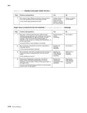
...assemblies, or broken gear teeth. Replace the 5-Bin Mailbox control board assembly. Replace the 5-Bin Mailbox control board assembly. 2-70 Service Manual Paper does not feed into bin x Step 1 Actions and questions Bin x sensor flag-Make sure the bin x sensor flag is ...correctly. It measures between approximately 30 ohms and 50 ohms. Is the resistance correct? Replace the solenoid assembly. Yes Replace parts or repairs necessary. Replace the mechanical linkage/DC motor assembly. Bin x solenoid-Check the resistance of the solenoid. Are parts broken, loose,...
...assemblies, or broken gear teeth. Replace the 5-Bin Mailbox control board assembly. Replace the 5-Bin Mailbox control board assembly. 2-70 Service Manual Paper does not feed into bin x Step 1 Actions and questions Bin x sensor flag-Make sure the bin x sensor flag is ...correctly. It measures between approximately 30 ohms and 50 ohms. Is the resistance correct? Replace the solenoid assembly. Yes Replace parts or repairs necessary. Replace the mechanical linkage/DC motor assembly. Bin x solenoid-Check the resistance of the solenoid. Are parts broken, loose,...
Service Manual
Page 114
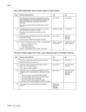
... questions Yes 1 Run Tray x sensor test from the Diagnostics Menu. Replace the paper level sensing assembly. No Go to step 4 Repair or replace as necessary. Make sure the autocompensator pick arm lift bellcrank is installed in the tray. No Go to step 3 Go to...to retract, stays in down position. Carefully replace the tray, and recheck to step 3 Install the bellcrank correctly. Remove the tray, and manually reset the autocompensator to its down position. Contact your next level of these parts loose, broken, or missing? Check the following for sensor...
... questions Yes 1 Run Tray x sensor test from the Diagnostics Menu. Replace the paper level sensing assembly. No Go to step 4 Repair or replace as necessary. Make sure the autocompensator pick arm lift bellcrank is installed in the tray. No Go to step 3 Go to...to retract, stays in down position. Carefully replace the tray, and recheck to step 3 Install the bellcrank correctly. Remove the tray, and manually reset the autocompensator to its down position. Contact your next level of these parts loose, broken, or missing? Check the following for sensor...
Service Manual
Page 120
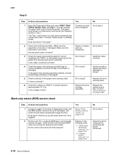
...Using the toggle ITU function in the following levels for correct installation at JTRAY1. Does the Sensor Test pass? Check continuity of support. Repair or replace parts as necessary. Replace the level sensing cable. Does the ITU belt move back and forth properly? Yes Go to "...TESTS, Sensor Test, and Tray 1. You can activate the paper level sensor inside the printer. Is there continuity? Locate the BOR gear, and manually activate the gear. Replace in diagnostics mode, test the BOR system. It should measure approximately +5 V dc. The paper level sensor is empty,...
...Using the toggle ITU function in the following levels for correct installation at JTRAY1. Does the Sensor Test pass? Check continuity of support. Repair or replace parts as necessary. Replace the level sensing cable. Does the ITU belt move back and forth properly? Yes Go to "...TESTS, Sensor Test, and Tray 1. You can activate the paper level sensor inside the printer. Is there continuity? Locate the BOR gear, and manually activate the gear. Replace in diagnostics mode, test the BOR system. It should measure approximately +5 V dc. The paper level sensor is empty,...
Service Manual
Page 122
...Make sure the ITU assembly interlock switch actuator is not damaged or broken and actuates the switch correctly. Check for part number.) 2-80 Service Manual Replace the ITU assembly. See "Front cover or front cover backplate assembly removal" on the cable connector. See "System board removal" on...open interlock cable assembly to system board-Make sure that the cable is correctly connected to step 4 Install the front cover correctly, or repair as necessary. Is there continuity? Go to step 7 Replace the system board. Replace the HVPS/cover open interlock cable assembly-Make sure ...
...Make sure the ITU assembly interlock switch actuator is not damaged or broken and actuates the switch correctly. Check for part number.) 2-80 Service Manual Replace the ITU assembly. See "Front cover or front cover backplate assembly removal" on the cable connector. See "System board removal" on...open interlock cable assembly to system board-Make sure that the cable is correctly connected to step 4 Install the front cover correctly, or repair as necessary. Is there continuity? Go to step 7 Replace the system board. Replace the HVPS/cover open interlock cable assembly-Make sure ...
Service Manual
Page 128
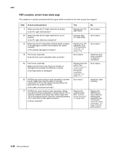
...) on the HCIT system board. Check the AC line voltage at the input to step 6 Replace the cables. 2-86 Service Manual Check the system board LED. Yes Go to the LVPS. Repair as necessary. Is the voltage correct? The voltage should measure approximately +5 V dc. Check the AC cable from the HCIT plugs...
...) on the HCIT system board. Check the AC line voltage at the input to step 6 Replace the cables. 2-86 Service Manual Check the system board LED. Yes Go to the LVPS. Repair as necessary. Is the voltage correct? The voltage should measure approximately +5 V dc. Check the AC cable from the HCIT plugs...
Service Manual
Page 152
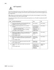
... HVPS board removal" on page 4-88. 3) ITU assembly. No Replace the second transfer cable. See "Second transfer roll removal" on page 4-49. 2-110 Service Manual Repair as necessary. Repair or replace as necessary. See "ITU assembly removal" on page 4-88. 2) Transfer HPVS board. 5061 Step 4 Actions and questions Check the continuity of support...
... HVPS board removal" on page 4-88. 3) ITU assembly. No Replace the second transfer cable. See "Second transfer roll removal" on page 4-49. 2-110 Service Manual Repair as necessary. Repair or replace as necessary. See "ITU assembly removal" on page 4-88. 2) Transfer HPVS board. 5061 Step 4 Actions and questions Check the continuity of support...


