
User's Guide
Page 60
...a web oiler upgrade kit to print large quantities of vinyl or dual web labels. Fuser and ITU Refer to the part number listed on the fuser or ITU for the appropriate reordering number for these items. Ordering a fuser Note: When the 87 Fuser Life Warning message appears on the... Cyan high yield Return Program print cartridge • Magenta high yield Return Program print cartridge • Yellow high yield Return Program print cartridge C772 • • • Black high yield print cartridge Cyan extra high yield print cartridge Magenta extra high yield print cartridge Yellow extra...
...a web oiler upgrade kit to print large quantities of vinyl or dual web labels. Fuser and ITU Refer to the part number listed on the fuser or ITU for the appropriate reordering number for these items. Ordering a fuser Note: When the 87 Fuser Life Warning message appears on the... Cyan high yield Return Program print cartridge • Magenta high yield Return Program print cartridge • Yellow high yield Return Program print cartridge C772 • • • Black high yield print cartridge Cyan extra high yield print cartridge Magenta extra high yield print cartridge Yellow extra...

User's Guide
Page 61
...three staple cartridges. Use part number 11K3188 to order an image transfer unit. Recycling Lexmark products 61 Recycling Lexmark products To return Lexmark products to Lexmark for recycling: 1 Visit our Web site: www.lexmark.com/recycle 2 Follow the instructions... on the publications CD Ordering staple cartridges Staple cartridges hold 3,000 staples. For more information about warning messages, see the Menus and Messages Guide on the computer screen. Maintaining the printer Ordering an image transfer unit and transfer roller When the 83.yy ITU...
...three staple cartridges. Use part number 11K3188 to order an image transfer unit. Recycling Lexmark products 61 Recycling Lexmark products To return Lexmark products to Lexmark for recycling: 1 Visit our Web site: www.lexmark.com/recycle 2 Follow the instructions... on the publications CD Ordering staple cartridges Staple cartridges hold 3,000 staples. For more information about warning messages, see the Menus and Messages Guide on the computer screen. Maintaining the printer Ordering an image transfer unit and transfer roller When the 83.yy ITU...

Menus and Messages Guide
Page 4
... equipment or the specified printer language. Menu Paper Menu Reports Settings Supplies Menu Cyan Cartridge Magenta Cartridge Yellow Cartridge Black Cartridge Waste Toner Box Fuser ITU Paper Menu Default Source Paper Size/Type Configure MP Substitute Size Paper Texture Paper Weight Paper Loading Custom Types Universal Setup Bin Setup Reports Menu... the values you can select these values at any time, but they only affect printer function when you to change printer settings. 1 Using printer menus A number of menus are available to make it easy for a particular printer language.
... equipment or the specified printer language. Menu Paper Menu Reports Settings Supplies Menu Cyan Cartridge Magenta Cartridge Yellow Cartridge Black Cartridge Waste Toner Box Fuser ITU Paper Menu Default Source Paper Size/Type Configure MP Substitute Size Paper Texture Paper Weight Paper Loading Custom Types Universal Setup Bin Setup Reports Menu... the values you can select these values at any time, but they only affect printer function when you to change printer settings. 1 Using printer menus A number of menus are available to make it easy for a particular printer language.
Menus and Messages Guide
Page 53
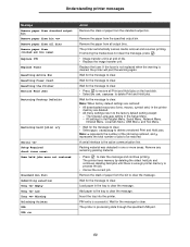
...active communication link. Wait for the message to the factory default setting except: - Note: x represents the number of the job being restored, and y represents the total number of jobs to clear the message and continue printing. Load paper in the printer memory are deleted. •... printer messages Message Remove paper from standard output bin Remove paper from bin Remove paper from all bins Remove paper from Replace ITU Replace Fuser Resetting Active Bin Resetting Fuser Count Resetting the Printer Restore Held Jobs Restoring Factory Defaults Restoring held job(s) x/y Serial...
...active communication link. Wait for the message to the factory default setting except: - Note: x represents the number of the job being restored, and y represents the total number of jobs to clear the message and continue printing. Load paper in the printer memory are deleted. •... printer messages Message Remove paper from standard output bin Remove paper from bin Remove paper from all bins Remove paper from Replace ITU Replace Fuser Resetting Active Bin Resetting Fuser Count Resetting the Printer Restore Held Jobs Restoring Factory Defaults Restoring held job(s) x/y Serial...

Help Menu Pages
Page 12
Supplies Menu Cyan Cartridge Magenta Cartridge Yellow Cartridge Black Cartridge Waste Toner Box Fuser ITU Paper Menu Default Source Paper Size/Type Configure MP Substitute Size Paper Texture Paper Weight Paper Loading Custom Types Universal Setup Bin Setup Reports Menu ... printer model or options installed. Some menu items may not be available based on the Software and Documentation CD. Menu map Page 1 of 2 Menu map A number of menus are available to make it easy to change printer settings.
Supplies Menu Cyan Cartridge Magenta Cartridge Yellow Cartridge Black Cartridge Waste Toner Box Fuser ITU Paper Menu Default Source Paper Size/Type Configure MP Substitute Size Paper Texture Paper Weight Paper Loading Custom Types Universal Setup Bin Setup Reports Menu ... printer model or options installed. Some menu items may not be available based on the Software and Documentation CD. Menu map Page 1 of 2 Menu map A number of menus are available to make it easy to change printer settings.
Help Menu Pages
Page 20
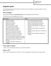
Fuser or ITU Refer to the part number listed on the fuser or ITU for the appropriate reordering number for print cartridge ordering information. Print cartridges Visit the lexmark Web site at www.lexmark.com for these items. C770 / C772 C772 • Black print cartridge • Cyan print cartridge &#...waste container To order a new toner waste container, order part number 10B3100. The following tables list the part numbers for ordering new print cartridges, toner waste containers, fusers, or image transfer units (ITU). Supplies guide Page 1 of 1 Supplies guide The following is...
Fuser or ITU Refer to the part number listed on the fuser or ITU for the appropriate reordering number for print cartridge ordering information. Print cartridges Visit the lexmark Web site at www.lexmark.com for these items. C770 / C772 C772 • Black print cartridge • Cyan print cartridge &#...waste container To order a new toner waste container, order part number 10B3100. The following tables list the part numbers for ordering new print cartridges, toner waste containers, fusers, or image transfer units (ITU). Supplies guide Page 1 of 1 Supplies guide The following is...
Service Manual
Page 121
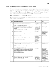
...Make sure the front cover assembly is closed and the ITU is correctly installed. See "System board removal" on page 7-37 for the printhead and HVPS. These cable/switches provide separate interlocks for the part number.) Replace the ITU light shield assembly. Go to step 5 Install the cable... correctly. See "ITU light shield assembly" on the front access door support and with the lower switch mounted on...
...Make sure the front cover assembly is closed and the ITU is correctly installed. See "System board removal" on page 7-37 for the printhead and HVPS. These cable/switches provide separate interlocks for the part number.) Replace the ITU light shield assembly. Go to step 5 Install the cable... correctly. See "ITU light shield assembly" on the front access door support and with the lower switch mounted on...
Service Manual
Page 122
... HVPS/cover open interlock cable assembly to system board-Make sure that the cable is correctly connected to J14 on the system board and the ITU autoconnect is seated correctly. Go to step 4 Install the front cover correctly, or repair as necessary. See "Front cover or front cover ...for continuity between J14-1 and J14-2 on the front access door support. Check for part number.) 2-80 Service Manual Is there continuity? Is the ITU light shield out of position. Yes Replace the ITU light shield. See "ITU assembly removal" on the system board. No Go to step 2 Go to step 3 ...
... HVPS/cover open interlock cable assembly to system board-Make sure that the cable is correctly connected to J14 on the system board and the ITU autoconnect is seated correctly. Go to step 4 Install the front cover correctly, or repair as necessary. See "Front cover or front cover ...for continuity between J14-1 and J14-2 on the front access door support. Check for part number.) 2-80 Service Manual Is there continuity? Is the ITU light shield out of position. Yes Replace the ITU light shield. See "ITU assembly removal" on the system board. No Go to step 2 Go to step 3 ...
Service Manual
Page 170
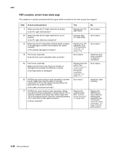
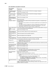
... to clear. Wait for the message to print. all output bins. Replace ITU • Image transfer unit is displayed. Resetting the Printer Wait for the message to delete Print and Hold jobs. Note: x represents the number of life. • Replace the image transfer unit. 5061 User attendance messages...restored: • All downloaded resources (fonts, macros, symbol sets) in the printer memory are being restored, and y represents the total number of paper from the specified output bin. If the error recurs, got to clear. If the fuser is not replaced when the warning ...
... to clear. Wait for the message to print. all output bins. Replace ITU • Image transfer unit is displayed. Resetting the Printer Wait for the message to delete Print and Hold jobs. Note: x represents the number of life. • Replace the image transfer unit. 5061 User attendance messages...restored: • All downloaded resources (fonts, macros, symbol sets) in the printer memory are being restored, and y represents the total number of paper from the specified output bin. If the error recurs, got to clear. If the fuser is not replaced when the warning ...
Service Manual
Page 212
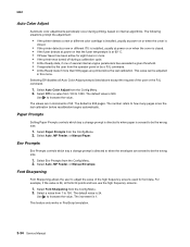
... 2. Select Auto Color Adjust from the Config Menu. 2. For example, if the value is 500. Use to how many pages since the last calibration. The number refers to increase the value. Select Env Prompts from the Config Menu. 2. This feature only works in increments of the user or the PJL command...a new or different color cartridge is installed, usually at power on or when the cover is closed. • If the printer detects a new or different ITU is installed, usually at power on or when the cover is closed. • If the fuser detects at 60° C. • If Power Saver ...
... 2. Select Auto Color Adjust from the Config Menu. 2. For example, if the value is 500. Use to how many pages since the last calibration. The number refers to increase the value. Select Env Prompts from the Config Menu. 2. This feature only works in increments of the user or the PJL command...a new or different color cartridge is installed, usually at power on or when the cover is closed. • If the printer detects a new or different ITU is installed, usually at power on or when the cover is closed. • If the fuser detects at 60° C. • If Power Saver ...
Service Manual
Page 230
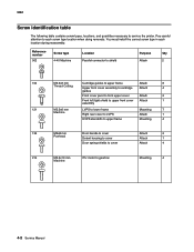
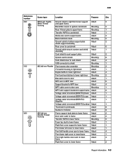
You must install the correct screw type in each screw type location when doing removals. Reference number 002 Screw type 4-40 Machine Location Parallel connector to shield Purpose Qty Attach 2 102 M3.5x8 mm Cartridge guides to upper frame ...133 M3x8 mm Door handle to cover Panhead Detent housing to cover Door spring shields to cover Attach 2 Attach 1 Attach 4 214 M3.5x10 mm ITU motor to each location during reassembly. Pay careful attention to gearbox Machine Mounting 4 4-2 Service Manual 5061 Screw identification table The following table contains screw ...
You must install the correct screw type in each screw type location when doing removals. Reference number 002 Screw type 4-40 Machine Location Parallel connector to shield Purpose Qty Attach 2 102 M3.5x8 mm Cartridge guides to upper frame ...133 M3x8 mm Door handle to cover Panhead Detent housing to cover Door spring shields to cover Attach 2 Attach 1 Attach 4 214 M3.5x10 mm ITU motor to each location during reassembly. Pay careful attention to gearbox Machine Mounting 4 4-2 Service Manual 5061 Screw identification table The following table contains screw ...
Service Manual
Page 231
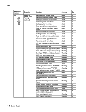
5061 Reference number Screw type Location Purpose Qty 232 M3x6 mm Taptite Ground cable to lower frame Attach 2 Repair information 4-3 Forming Blank INA covers to system card shield ... to shield Mounting 8 Card shield cover to card shield Attach 4 USB connector to shield Mounting 1 312 M2.9x6 mm Plastite Front access door assembly Mounting 3 ITU switch housing to light shield Attach 1 Duplex baffle to lower right door Attach 4 Front and rear latches to lower right door Mounting 2 Bias latch cover...
5061 Reference number Screw type Location Purpose Qty 232 M3x6 mm Taptite Ground cable to lower frame Attach 2 Repair information 4-3 Forming Blank INA covers to system card shield ... to shield Mounting 8 Card shield cover to card shield Attach 4 USB connector to shield Mounting 1 312 M2.9x6 mm Plastite Front access door assembly Mounting 3 ITU switch housing to light shield Attach 1 Duplex baffle to lower right door Attach 4 Front and rear latches to lower right door Mounting 2 Bias latch cover...
Service Manual
Page 232
5061 Reference number Screw type Location Purpose Qty 323 M3.5x8 mm Left lower cover ...Top cover asm to upper front cover Attach 3 Top cover asm to card shield Attach 1 ITU light shield asm to upper front guide Attach 1 ITU Ribs to upper redrive door Mounting 5 Upper door hinges to upper frame (redrive) Mounting 2...to upper frame (redrive) Mounting 2 Developer HVPS to cartridge contact asm Mounting 4 BOR drive asm to upper frame Mounting 1 ITU drive asm to lower frame Mounting 3 Fuser drive asm to lower frame Mounting 4 Vacuum top duct to lower frame Mounting 2...
5061 Reference number Screw type Location Purpose Qty 323 M3.5x8 mm Left lower cover ...Top cover asm to upper front cover Attach 3 Top cover asm to card shield Attach 1 ITU light shield asm to upper front guide Attach 1 ITU Ribs to upper redrive door Mounting 5 Upper door hinges to upper frame (redrive) Mounting 2...to upper frame (redrive) Mounting 2 Developer HVPS to cartridge contact asm Mounting 4 BOR drive asm to upper frame Mounting 1 ITU drive asm to lower frame Mounting 3 Fuser drive asm to lower frame Mounting 4 Vacuum top duct to lower frame Mounting 2...
Service Manual
Page 263
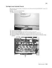
Warning: Do not remove the printheads. 1. See "ITU assembly removal" on page 7-28 for the part numbers. Remove the top cover assembly. Open the front cover assembly. 2. Remove the ITU assembly. 5061 Cartridge contact assembly removal See "Cartridge contact assembly, complete Also order cable tie parts packet (P/N 40X1648)" on page 4-49. 4. Remove the toner...
Warning: Do not remove the printheads. 1. See "ITU assembly removal" on page 7-28 for the part numbers. Remove the top cover assembly. Open the front cover assembly. 2. Remove the ITU assembly. 5061 Cartridge contact assembly removal See "Cartridge contact assembly, complete Also order cable tie parts packet (P/N 40X1648)" on page 4-49. 4. Remove the toner...
Service Manual
Page 277
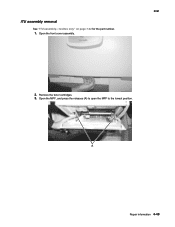
Repair information 4-49 Remove the toner cartridges. 3. Open the MPF, and press the releases (A) to open the MPF to the lowest position. ITU assembly removal See "ITU assembly-1xx/3xx only" on page 7-22 for the part number. 1. Open the front cover assembly. 5061 2.
Repair information 4-49 Remove the toner cartridges. 3. Open the MPF, and press the releases (A) to open the MPF to the lowest position. ITU assembly removal See "ITU assembly-1xx/3xx only" on page 7-22 for the part number. 1. Open the front cover assembly. 5061 2.
Service Manual
Page 280
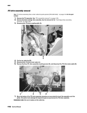
... cartridge drive assembly. Disconnect the ITU drive motor cable (C). 6. Remove the three ITU drive assembly mounting screws (D), and disconnect the ITU drive motor cable (D). 7. A 4. See the removal for the part number. 1. Be careful not to replace all the cable ties. 4-52 Service Manual 5061 ITU drive assembly removal See "ITU drive assembly Also order cable tie...
... cartridge drive assembly. Disconnect the ITU drive motor cable (C). 6. Remove the three ITU drive assembly mounting screws (D), and disconnect the ITU drive motor cable (D). 7. A 4. See the removal for the part number. 1. Be careful not to replace all the cable ties. 4-52 Service Manual 5061 ITU drive assembly removal See "ITU drive assembly Also order cable tie...
Service Manual
Page 307
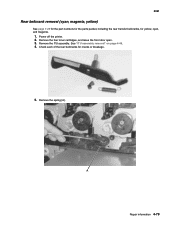
Power off the printer. 2. Check each of the rear bellcranks for yellow, cyan, and magenta. 1. See "ITU assembly removal" on page 4-49. 4. Remove the ITU assembly. Repair information 4-79 Remove the spring (A). Remove the four toner cartridges, and leave the front door open. 3. 5061 Rear bellcrank removal (cyan, magenta, yellow) See page 7-25 for the part numbers for the parts packet, including the rear transfer bellcranks, for cracks or breakage. 5.
Power off the printer. 2. Check each of the rear bellcranks for yellow, cyan, and magenta. 1. See "ITU assembly removal" on page 4-49. 4. Remove the ITU assembly. Repair information 4-79 Remove the spring (A). Remove the four toner cartridges, and leave the front door open. 3. 5061 Rear bellcrank removal (cyan, magenta, yellow) See page 7-25 for the part numbers for the parts packet, including the rear transfer bellcranks, for cracks or breakage. 5.
Service Manual
Page 309
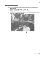
Power off the printer. 2. Remove the spring. 6. Remove the ITU assembly. See "ITU assembly removal" on page 4-49. 4. Check each of the rear bellcranks for black. 1. Be careful not to remove the screw. Recommend using a magnetic tipped screwdriver to lose the washers. Repair information 4-81 Remove the stop screw (A) and two washers (B). Remove the four toner cartridges, and leave the front door open. 3. 5061 Rear bellcrank (black) removal See page 7-25 for the part number for the parts packet, including the rear transfer bellcranks, for cracks or breakage. 5.
Power off the printer. 2. Remove the spring. 6. Remove the ITU assembly. See "ITU assembly removal" on page 4-49. 4. Check each of the rear bellcranks for black. 1. Be careful not to remove the screw. Recommend using a magnetic tipped screwdriver to lose the washers. Repair information 4-81 Remove the stop screw (A) and two washers (B). Remove the four toner cartridges, and leave the front door open. 3. 5061 Rear bellcrank (black) removal See page 7-25 for the part number for the parts packet, including the rear transfer bellcranks, for cracks or breakage. 5.
Service Manual
Page 316
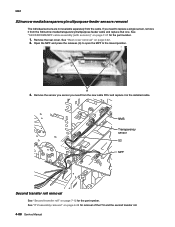
...need from the new cable FRU and replace it from the cable. See "ITU assembly removal" on page 7-37 for the part number. 1. See "S2/XPAR/NMS/MPF cable assembly (with sensors)" on page 4-49 for the part number. Remove the rear cover. Second transfer roll removal See "Second transfer roll"... on page 4-22. 2. See "Rear cover removal" on page 7-12 for removal of the ITU and the second transfer roll. 4-88 Service Manual 5061 S2/narrow...
...need from the new cable FRU and replace it from the cable. See "ITU assembly removal" on page 7-37 for the part number. 1. See "S2/XPAR/NMS/MPF cable assembly (with sensors)" on page 4-49 for the part number. Remove the rear cover. Second transfer roll removal See "Second transfer roll"... on page 4-22. 2. See "Rear cover removal" on page 7-12 for removal of the ITU and the second transfer roll. 4-88 Service Manual 5061 S2/narrow...
Service Manual
Page 322
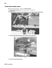
5061 Transfer plate assembly removal See "Transfer plate assembly" on page 4-49. 2. Remove the ITU assembly. Remove the transfer plate assembly. 4-94 Service Manual Remove tray 1. 3. A 5. Remove the grounding strap (A) attached to the bottom of the transfer plate up to a 45° angle to release the transfer plate. 4. See "ITU assembly removal" on page 7-12 for the part number. 1. Lifting and rotate the right edge of the transfer plate.
5061 Transfer plate assembly removal See "Transfer plate assembly" on page 4-49. 2. Remove the ITU assembly. Remove the transfer plate assembly. 4-94 Service Manual Remove tray 1. 3. A 5. Remove the grounding strap (A) attached to the bottom of the transfer plate up to a 45° angle to release the transfer plate. 4. See "ITU assembly removal" on page 7-12 for the part number. 1. Lifting and rotate the right edge of the transfer plate.


