Service Manual
Page 3
... Noise Service Check 2-14 Auto Sheet Feeder (ASF) Service Check 2-15 Carrier Drive, Home Position Sensor, Ribbon Feed Service Check 2-17 Intermittent Problem Service Check 2-20 No Print or Abnormal Print Service Check 2-23 Operator Panel Service Check 2-24 Paper Empty Sensor Service Check 2-26 Paper Feed Service Check 2-27 Paper Select Sensor Service Check 2-30 POST Service Check 2-31 Power Service Check 2-32 Print Speed Service Check 2-34 Printhead Service Check 2-36 Pull Tractor Sensor Service Check 2-38 Top of Forms Problem Service Check 2-39 Tractor 2 Service Check 2-40...
... Noise Service Check 2-14 Auto Sheet Feeder (ASF) Service Check 2-15 Carrier Drive, Home Position Sensor, Ribbon Feed Service Check 2-17 Intermittent Problem Service Check 2-20 No Print or Abnormal Print Service Check 2-23 Operator Panel Service Check 2-24 Paper Empty Sensor Service Check 2-26 Paper Feed Service Check 2-27 Paper Select Sensor Service Check 2-30 POST Service Check 2-31 Power Service Check 2-32 Print Speed Service Check 2-34 Printhead Service Check 2-36 Pull Tractor Sensor Service Check 2-38 Top of Forms Problem Service Check 2-39 Tractor 2 Service Check 2-40...

Service Manual
Page 4
...4-23 Head Gap Sensor Removal (23XX-002, 003 4-24 Home Position Sensor Removal 4-25 Label Jam Removal 4-26 Left Side Frame Removal 4-28 Lower Feed Roller Removal 4-30 Lower Pinch Roller Removal 4-32 Main Logic Board Removal 4-33 Operator Panel Assembly Removal 4-34 Paper Empty Sensor And Spring Removal 4-36 Paper Feed Motor Removal 4-38 Paper Guide Removal (Left And Right 4-39 Paper Guide / Platen Assembly Removal 4-40 Paper Select Lever Removal 4-42 Paper Select Sensor Removal 4-43 Paper Separator Removal 4-44 Power Supply Removal 4-46 Print Unit Removal 4-47 Printhead Removal...
...4-23 Head Gap Sensor Removal (23XX-002, 003 4-24 Home Position Sensor Removal 4-25 Label Jam Removal 4-26 Left Side Frame Removal 4-28 Lower Feed Roller Removal 4-30 Lower Pinch Roller Removal 4-32 Main Logic Board Removal 4-33 Operator Panel Assembly Removal 4-34 Paper Empty Sensor And Spring Removal 4-36 Paper Feed Motor Removal 4-38 Paper Guide Removal (Left And Right 4-39 Paper Guide / Platen Assembly Removal 4-40 Paper Select Lever Removal 4-42 Paper Select Sensor Removal 4-43 Paper Separator Removal 4-44 Power Supply Removal 4-46 Print Unit Removal 4-47 Printhead Removal...

Service Manual
Page 11
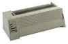
... manual is divided into the following chapters: • "General Information" contains a general description of the printer and the maintenance approach used to locate or repeat symptoms of printer problems. • "Repair Information" provides instructions for making printer adjustments and removing and installing FRUs. • "Connector Locations" uses illustrations to identify the major components and test points on the printer. • "Preventive Maintenance" contains lubrication specifications, and maintenance information to repair...
... manual is divided into the following chapters: • "General Information" contains a general description of the printer and the maintenance approach used to locate or repeat symptoms of printer problems. • "Repair Information" provides instructions for making printer adjustments and removing and installing FRUs. • "Connector Locations" uses illustrations to identify the major components and test points on the printer. • "Preventive Maintenance" contains lubrication specifications, and maintenance information to repair...

Service Manual
Page 19
...; Except as a FRU. • Changes to the 23XX-002, but different switch definitions. • All units have a power lead. • Switch settings are valid only after printer power is available as noted, all printers. • Some adapters may be installed on printers other than what is listed. • Only the "Black" adapter is turned off and then on again. • Contact Lexmark Technical Support for "Black".
...; Except as a FRU. • Changes to the 23XX-002, but different switch definitions. • All units have a power lead. • Switch settings are valid only after printer power is available as noted, all printers. • Some adapters may be installed on printers other than what is listed. • Only the "Black" adapter is turned off and then on again. • Contact Lexmark Technical Support for "Black".

Service Manual
Page 27
... Tractor 2 is installed, remove it to "Carrier Drive, Home Position Sensor, Ribbon Feed Service Check" on page 2-20. Diagnostic Information 2-3 If you get the same error during powerup, replace the main logic board and readjust the bidirectional print adjustment. Refer to "Intermittent Problem Service Check" on page 2-17. If the printer completes POST successfully and eventually gets the same error, go to the "Tractor 2 Service Check" on . LED Power Ready Paper Font Pitch Alt Others Status ON BLINK BLINK BLINK BLINK...
... Tractor 2 is installed, remove it to "Carrier Drive, Home Position Sensor, Ribbon Feed Service Check" on page 2-20. Diagnostic Information 2-3 If you get the same error during powerup, replace the main logic board and readjust the bidirectional print adjustment. Refer to "Intermittent Problem Service Check" on page 2-17. If the printer completes POST successfully and eventually gets the same error, go to the "Tractor 2 Service Check" on . LED Power Ready Paper Font Pitch Alt Others Status ON BLINK BLINK BLINK BLINK...

Service Manual
Page 31
... paper select lever is enabled in the cut sheet position. Go to the "Print Speed Service Check" on page 2-23. Abnormal Print Operation Problems Symptom Printer will not print from the computer correctly. Auto sheet feeder has intermittent feed problems. Action Be sure Sheet Feed is in the Setup Mode. Undefined or incorrect character(s). If the serial interface adapter is connected properly. Abnormal operation, incorrect characters, or incorrect line width. Auto sheet feeder double feeds. Diagnostic Information 2-7 Go to the "No Print or Abnormal Print Service Check...
... paper select lever is enabled in the cut sheet position. Go to the "Print Speed Service Check" on page 2-23. Abnormal Print Operation Problems Symptom Printer will not print from the computer correctly. Auto sheet feeder has intermittent feed problems. Action Be sure Sheet Feed is in the Setup Mode. Undefined or incorrect character(s). If the serial interface adapter is connected properly. Abnormal operation, incorrect characters, or incorrect line width. Auto sheet feeder double feeds. Diagnostic Information 2-7 Go to the "No Print or Abnormal Print Service Check...
Service Manual
Page 35
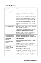
..., the ribbon cartridge needs to 0. Uneven print density across the print line. Clean the printhead nose. Print Quality Problems Symptom No print, but carrier moves as if printing. Print density is connected properly. Specific dots missing. Action Adjust the form thickness lever to the "Carrier Drive, Home Position Sensor, Ribbon Feed Service Check" on page 2-17. Be sure the interface cable is light. Check the ribbon cartridge for binds or damage. Go to be replaced. Clean the printhead. Clean the ribbon guide and...
..., the ribbon cartridge needs to 0. Uneven print density across the print line. Clean the printhead nose. Print Quality Problems Symptom No print, but carrier moves as if printing. Print density is connected properly. Specific dots missing. Action Adjust the form thickness lever to the "Carrier Drive, Home Position Sensor, Ribbon Feed Service Check" on page 2-17. Be sure the interface cable is light. Check the ribbon cartridge for binds or damage. Go to be replaced. Clean the printhead. Clean the ribbon guide and...
Service Manual
Page 37
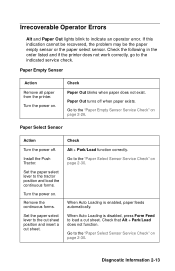
... cut sheet position and insert a cut sheet. Check that Alt + Park/Load does not function. Go to the tractor position and load the continuous forms. Turn the power on page 2-30. Go to the indicated service check. Check Alt + Park/Load function correctly. Diagnostic Information 2-13 Install the Push Tractor. Paper Out turns off . Remove the continuous forms. Set the paper select lever to load a cut sheet. Turn the power on page 2-30. When Auto Loading is enabled, paper feeds automatically. Paper Empty Sensor Action Remove all paper from the printer...
... cut sheet position and insert a cut sheet. Check that Alt + Park/Load does not function. Go to the tractor position and load the continuous forms. Turn the power on page 2-30. Go to the indicated service check. Check Alt + Park/Load function correctly. Diagnostic Information 2-13 Install the Push Tractor. Paper Out turns off . Remove the continuous forms. Set the paper select lever to load a cut sheet. Turn the power on page 2-30. When Auto Loading is enabled, paper feeds automatically. Paper Empty Sensor Action Remove all paper from the printer...
Service Manual
Page 39
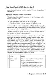
... feed rollers. It is then fed to the "Paper Select Sensor Service Check" on page 1-6. Diagnostic Information 2-15 The ASF contains no electrical parts. The combination lock mechanism is selected on the inside of the printer's right side frame. FRU 1 Paper Select Sensor Action With the paper select lever in the Setup menu. Refer to load a sheet with the ASF installed by the paper. To use the ASF: • The paper select lever must be set to cut sheet position...
... feed rollers. It is then fed to the "Paper Select Sensor Service Check" on page 1-6. Diagnostic Information 2-15 The ASF contains no electrical parts. The combination lock mechanism is selected on the inside of the printer's right side frame. FRU 1 Paper Select Sensor Action With the paper select lever in the Setup menu. Refer to load a sheet with the ASF installed by the paper. To use the ASF: • The paper select lever must be set to cut sheet position...
Service Manual
Page 47
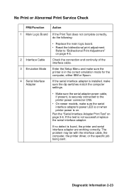
... Board If the Print Test does not complete correctly, do the following: 2 Interface Cable 3 Emulation Mode 4 Serial Interface Adapter • Replace the main logic board. • Reset the bidirectional print adjustment. Refer to the printer power connector CN5. • On newer models, make sure the printer is on when printer power is in the correct emulation mode for the computer, either IBM or Epson. The problem may be with the interface cable, the computer, the printer driver, or the specific job...
... Board If the Print Test does not complete correctly, do the following: 2 Interface Cable 3 Emulation Mode 4 Serial Interface Adapter • Replace the main logic board. • Reset the bidirectional print adjustment. Refer to the printer power connector CN5. • On newer models, make sure the printer is on when printer power is in the correct emulation mode for the computer, either IBM or Epson. The problem may be with the interface cable, the computer, the printer driver, or the specific job...
Service Manual
Page 50
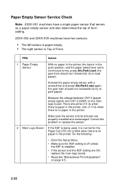
... left sensor is paper empty. • The right sensor is no paper in the push position, and the paper select lever set to blink when there is installed. • If the sensor and the ASF setting are properly installed and undamaged. the gear train should turn forward (to try to load paper). the gear train should turn backward (to try to park paper). Paper Empty Sensor Service Check Note: 23XX-001 machines have a single paper sensor...
... left sensor is paper empty. • The right sensor is no paper in the push position, and the paper select lever set to blink when there is installed. • If the sensor and the ASF setting are properly installed and undamaged. the gear train should turn forward (to try to load paper). the gear train should turn backward (to try to park paper). Paper Empty Sensor Service Check Note: 23XX-001 machines have a single paper sensor...
Service Manual
Page 51
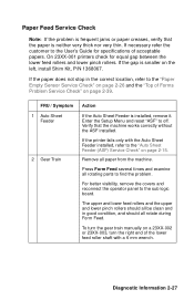
...) Service Check" on page 2-39. Press Form Feed several times and examine all paper from the machine. To turn the gear train manually on the left, install Shim Kit, P/N 1368067. On 23XX-001 printers check for specifications of the lower feed roller shaft with the Auto Sheet Feeder installed, refer to the User's Guide for equal gap between the lower feed rollers and lower pinch rollers. Remove all rotating parts to the sub logic board. The...
...) Service Check" on page 2-39. Press Form Feed several times and examine all paper from the machine. To turn the gear train manually on the left, install Shim Kit, P/N 1368067. On 23XX-001 printers check for specifications of the lower feed roller shaft with the Auto Sheet Feeder installed, refer to the User's Guide for equal gap between the lower feed rollers and lower pinch rollers. Remove all rotating parts to the sub logic board. The...

Service Manual
Page 53
... not change from the printer and place the tractor in the cut sheet position (sensor open , Park/Load will try to the "Pull Tractor Sensor Service Check" on page 4-5. If no other problem is moved. If the pull tractor sensor has failed to close, Park/Load and Auto Tear Off will feed all paper from zero to infinite as the paper select lever is found replace the main logic board. Diagnostic Information 2-29 Reset the "Bidirectional Print Adjustment" on...
... not change from the printer and place the tractor in the cut sheet position (sensor open , Park/Load will try to the "Pull Tractor Sensor Service Check" on page 4-5. If no other problem is moved. If the pull tractor sensor has failed to close, Park/Load and Auto Tear Off will feed all paper from zero to infinite as the paper select lever is found replace the main logic board. Diagnostic Information 2-29 Reset the "Bidirectional Print Adjustment" on...

Service Manual
Page 55
... pull tractor sensor can cause POST errors. Disconnect the interface cable from the printer and turn the printer off and then on page 2-32. 2 Cables A faulty interface cable can cause Alt + Park/Load not to the main logic board and sub logic board. 3 Operator Panel Check the condition and continuity of the operator panel cable. If no problem is held down and releasing the left pull tractor actuator. If it does, go to "Bidirectional Print Adjustment" on...
... pull tractor sensor can cause POST errors. Disconnect the interface cable from the printer and turn the printer off and then on page 2-32. 2 Cables A faulty interface cable can cause Alt + Park/Load not to the main logic board and sub logic board. 3 Operator Panel Check the condition and continuity of the operator panel cable. If no problem is held down and releasing the left pull tractor actuator. If it does, go to "Bidirectional Print Adjustment" on...

Service Manual
Page 58
... at Forms Thickness 4 through 7. Head Gap Sensor contains one switch. No Head Gap Sensor. Head Gap Sensor Assembly contains two switches. 2-34 Depending on the job content, thermal slowdown may print slowly due to data throughput limitations. Print Speed Service Check Reduced speed while printing the top 2 inch (51 mm) of continuous operation on 239X-001 printers and after 5 to 10 minutes of a job is built into the printhead on 239X printers and protects the printhead from...
... at Forms Thickness 4 through 7. Head Gap Sensor contains one switch. No Head Gap Sensor. Head Gap Sensor Assembly contains two switches. 2-34 Depending on the job content, thermal slowdown may print slowly due to data throughput limitations. Print Speed Service Check Reduced speed while printing the top 2 inch (51 mm) of continuous operation on 239X-001 printers and after 5 to 10 minutes of a job is built into the printhead on 239X printers and protects the printhead from...

Service Manual
Page 63
... 5 V dc. Reset the "Bidirectional Print Adjustment" on page 4-5. Measure the voltage between main logic board CN8-2 (TOF signal) and CN8-3 (GND). • When there is paper in the printer the voltage should be 0 V dc. • When there is still a problem. Diagnostic Information 2-39 Top of Forms Problem Service Check Note: This service check applies to the cut sheet position and turn the power on. FRU Action 1 Top of Form Sensor Check that...
... 5 V dc. Reset the "Bidirectional Print Adjustment" on page 4-5. Measure the voltage between main logic board CN8-2 (TOF signal) and CN8-3 (GND). • When there is paper in the printer the voltage should be 0 V dc. • When there is still a problem. Diagnostic Information 2-39 Top of Forms Problem Service Check Note: This service check applies to the cut sheet position and turn the power on. FRU Action 1 Top of Form Sensor Check that...

Service Manual
Page 69
...Trade default paper sizes. Head Gap Sensor Test: Macro LEDs indicate sensor position. Diagnostic Aids 3-1 Sets printer in Hex Dump mode. Resets to US default paper sizes. Types of self tests are as follows: • Power-On Self Test (POST) • Print Test • Hex Dump Mode (a computer or terminal is needed) • Serial Interface Adapter Print Test The following are special machine modes that run these tests. Disables/Enables Operator Panel Lockout Mode. Diagnostic Aids The printer contains self tests to help find and solve problems. You need not connect the printer to...
...Trade default paper sizes. Head Gap Sensor Test: Macro LEDs indicate sensor position. Diagnostic Aids 3-1 Sets printer in Hex Dump mode. Resets to US default paper sizes. Types of self tests are as follows: • Power-On Self Test (POST) • Print Test • Hex Dump Mode (a computer or terminal is needed) • Serial Interface Adapter Print Test The following are special machine modes that run these tests. Disables/Enables Operator Panel Lockout Mode. Diagnostic Aids The printer contains self tests to help find and solve problems. You need not connect the printer to...

Service Manual
Page 71
... horizontal lines at the print position; If the printout is operating correctly. Note that the right margin is set to 13.6 inches. • After you test and troubleshoot the printer. Press Start/Stop. To stop the printer test, turn the printer on page 3-4. Press Start/Stop to be sure wide paper is parked. 2. test does not print if paper is loaded in sequence from top to bottom. Diagnostic Aids 3-3 Release Line Feed when the printing starts. 4. Service...
... horizontal lines at the print position; If the printout is operating correctly. Note that the right margin is set to 13.6 inches. • After you test and troubleshoot the printer. Press Start/Stop. To stop the printer test, turn the printer on page 3-4. Press Start/Stop to be sure wide paper is parked. 2. test does not print if paper is loaded in sequence from top to bottom. Diagnostic Aids 3-3 Release Line Feed when the printing starts. 4. Service...

Service Manual
Page 78
.... 4-4 Install the ribbon access cover. 14. and 0.016 in.), move the right carrier bushing [2] forward or backward until the gap between 0.35 mm - 0.40 mm (0.014 in. - 0.016 in . Install the ribbon cartridge and paper. 13. 7. Using feeler gauges [1] of the printing. Repeat Steps 5 and 6 and readjust the gap if necessary. 10. Move the carrier so that it is between the printhead [3] and platen [4] is...
.... 4-4 Install the ribbon access cover. 14. and 0.016 in.), move the right carrier bushing [2] forward or backward until the gap between 0.35 mm - 0.40 mm (0.014 in. - 0.016 in . Install the ribbon cartridge and paper. 13. 7. Using feeler gauges [1] of the printing. Repeat Steps 5 and 6 and readjust the gap if necessary. 10. Move the carrier so that it is between the printhead [3] and platen [4] is...

Service Manual
Page 203
... M Models available 1-1 O Operator Errors Irrecoverable 2-13 P Parts Auto Sheet Feeder Covers 7-28 Roller 7-26 Side Frame 7-28 Support 7-26 Carrier 7-10 Covers 7-6, 7-8 Electronics 7-20 Feed Roller 7-16 Paper Guide 7-16 Platen 7-16 Tractor 2 Option 7-30 Parts catalog How to use 7-1 Preventive Maintenance 6-1 Lubrication 6-1 Lubrication Points 6-2 Specified Lubricants 6-1 R Removal Procedures 4-7 Removals ASF Pick-up Roller 4-9 Auto Sheet Feeder Gears 4-8 Bottom Cover 4-10 Carrier 4-12 Carrier Motor Assembly 4-16 Carrier Plate 4-18 Download Buffer 4-21 Form Thickness Lever 4-22 Head Gap Sensor...
... M Models available 1-1 O Operator Errors Irrecoverable 2-13 P Parts Auto Sheet Feeder Covers 7-28 Roller 7-26 Side Frame 7-28 Support 7-26 Carrier 7-10 Covers 7-6, 7-8 Electronics 7-20 Feed Roller 7-16 Paper Guide 7-16 Platen 7-16 Tractor 2 Option 7-30 Parts catalog How to use 7-1 Preventive Maintenance 6-1 Lubrication 6-1 Lubrication Points 6-2 Specified Lubricants 6-1 R Removal Procedures 4-7 Removals ASF Pick-up Roller 4-9 Auto Sheet Feeder Gears 4-8 Bottom Cover 4-10 Carrier 4-12 Carrier Motor Assembly 4-16 Carrier Plate 4-18 Download Buffer 4-21 Form Thickness Lever 4-22 Head Gap Sensor...


