User Manual
Page 5
... device drivers 11 Opening the cover 12 Locating components 13 Accessing system board components and drives . . 14 Identifying parts on the system board . . . . . 15 Installing memory 16 Installing PCI adapters 17 Removing and replacing the battery 18 Removing and replacing an optical drive . . . . 19 Removing and replacing a diskette drive . . . . 20 Installing...
... device drivers 11 Opening the cover 12 Locating components 13 Accessing system board components and drives . . 14 Identifying parts on the system board . . . . . 15 Installing memory 16 Installing PCI adapters 17 Removing and replacing the battery 18 Removing and replacing an optical drive . . . . 19 Removing and replacing a diskette drive . . . . 20 Installing...
User Manual
Page 16
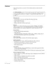
...HyperThreading Technology v Intel Pentium 4 processor v Intel® Celeron™ processor v Internal cache (size varies by model type) Memory Support for two 184-pin dual inline memory modules (DIMMs). v Microphone and headphone connectors on the front panel v Line-in and line-out connectors on the rear ...an overview of models. For a listing of features for a system maximum of PC2700 double data rate (DDR) synchronous dynamic random access memory (SDRAM) for your specific model, go to 1 GB of 2 GB. System summary The following information covers a variety of the computer features...
...HyperThreading Technology v Intel Pentium 4 processor v Intel® Celeron™ processor v Internal cache (size varies by model type) Memory Support for two 184-pin dual inline memory modules (DIMMs). v Microphone and headphone connectors on the front panel v Line-in and line-out connectors on the rear ...an overview of models. For a listing of features for a system maximum of PC2700 double data rate (DDR) synchronous dynamic random access memory (SDRAM) for your specific model, go to 1 GB of 2 GB. System summary The following information covers a variety of the computer features...
User Manual
Page 17
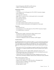
... include: v User and administrator passwords v Support for the addition of a cable lock such as a Kensington lock v Knockout holes for PCI-e DVI-D Connection Adapter v Two DIMM memory connectors Power v 225 Watt power supply with the built-in the network (by associating certificates with manual voltage selection switch v Automatic 50/60 Hz input...
... include: v User and administrator passwords v Support for the addition of a cable lock such as a Kensington lock v Knockout holes for PCI-e DVI-D Connection Adapter v Two DIMM memory connectors Power v 225 Watt power supply with the built-in the network (by associating certificates with manual voltage selection switch v Automatic 50/60 Hz input...
User Manual
Page 19
... 5 Audio devices, such as printers, joysticks, and scanners - USB devices, such as external speakers for the sound system - PCI Express x1 adaptors - System memory, called dual inline memory modules (DIMMs) - CD-ROM, DVD-ROM, or CD-RW drive, hard disk drive, diskette drive, and other removable media drives For the latest information...
... 5 Audio devices, such as printers, joysticks, and scanners - USB devices, such as external speakers for the sound system - PCI Express x1 adaptors - System memory, called dual inline memory modules (DIMMs) - CD-ROM, DVD-ROM, or CD-RW drive, hard disk drive, diskette drive, and other removable media drives For the latest information...

User Manual
Page 23
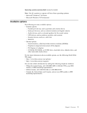
...take these instructions along with the instructions that come with the option. Installing options This chapter provides instructions for installing optional memory, PCI adapters, drives, and security features. Handling static-sensitive devices Static electricity, although harmless to which you install ...or remove any exposed circuitry. Chapter 2. Important Before you can seriously damage computer components and options. Handle adapters and memory modules by the edges. Installing external options This section shows the various external connectors on page v. v Prevent others from...
...take these instructions along with the instructions that come with the option. Installing options This chapter provides instructions for installing optional memory, PCI adapters, drives, and security features. Handling static-sensitive devices Static electricity, although harmless to which you install ...or remove any exposed circuitry. Chapter 2. Important Before you can seriously damage computer components and options. Handle adapters and memory modules by the edges. Installing external options This section shows the various external connectors on page v. v Prevent others from...
User Manual
Page 27
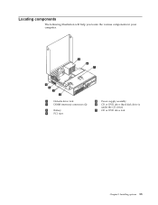
Locating components The following illustration will help you locate the various components in your computer. 1 Diskette drive lock 2 DIMM (memory) connectors (2) 3 Battery 4 PCI riser 5 Power supply assembly 6 CD or DVD drive (hard disk drive is under the CD drive) 7 CD or DVD drive lock Chapter 2. Installing options 13
Locating components The following illustration will help you locate the various components in your computer. 1 Diskette drive lock 2 DIMM (memory) connectors (2) 3 Battery 4 PCI riser 5 Power supply assembly 6 CD or DVD drive (hard disk drive is under the CD drive) 7 CD or DVD drive lock Chapter 2. Installing options 13
User Manual
Page 28
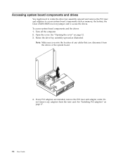
..." on page 12. 3. Open the cover. Do not remove any adapters from the drives or the system board. 4. Rotate the drive bay assembly upward as memory, the battery, the Clear CMOS/BIOS recovery jumper and to access the drives. Note: Make sure you disconnect from the riser card. Turn off the...
..." on page 12. 3. Open the cover. Do not remove any adapters from the drives or the system board. 4. Rotate the drive bay assembly upward as memory, the battery, the Clear CMOS/BIOS recovery jumper and to access the drives. Note: Make sure you disconnect from the riser card. Turn off the...
User Manual
Page 29
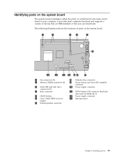
... The system board (sometimes called the planar or motherboard) is the main circuit board in your computer. Identifying parts on the system board. 1 Fan connectors (2) 2 Memory DIMM connectors (2) 3 SATA IDE hard disk drive connectors (2) 4 Riser connector 5 CMOS Battery 6 Clear CMOS/BIOS recovery jumper 7 Internal speaker connector 8 Diskette drive connector 9 Power button...
... The system board (sometimes called the planar or motherboard) is the main circuit board in your computer. Identifying parts on the system board. 1 Fan connectors (2) 2 Memory DIMM connectors (2) 3 SATA IDE hard disk drive connectors (2) 4 Riser connector 5 CMOS Battery 6 Clear CMOS/BIOS recovery jumper 7 Internal speaker connector 8 Diskette drive connector 9 Power button...
User Manual
Page 30
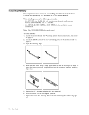
...16 User Guide Note: Only DDR SDRAM DIMMs can be used. See "Accessing system board components and drives" on page 15. 3. Push or insert the memory module straight down into the connector until the retaining clips close. 5. To install DIMMs: 1. See "Identifying parts on the system board" on page 14... cover and connecting the cables" on the connector. Locate the DIMM connectors. Place the drives back to a maximum of 2 GB of system memory. Open the retaining clips. 4. Replace the cover. Replace the PCI riser and adapters if it was removed. 6. Access the system board.
...16 User Guide Note: Only DDR SDRAM DIMMs can be used. See "Accessing system board components and drives" on page 15. 3. Push or insert the memory module straight down into the connector until the retaining clips close. 5. To install DIMMs: 1. See "Identifying parts on the system board" on page 14... cover and connecting the cables" on the connector. Locate the DIMM connectors. Place the drives back to a maximum of 2 GB of system memory. Open the retaining clips. 4. Replace the cover. Replace the PCI riser and adapters if it was removed. 6. Access the system board.

User Manual
Page 32
... cover" on page 24. Remove the PCI riser and PCI adapters that maintains the date, time, and settings for information about replacing and disposing of memory that impede access to the appropriate section. Reinstall the PCI riser and adapters. 8. What to do next: v To work safely. 6. Close the cover. See "Closing...
... cover" on page 24. Remove the PCI riser and PCI adapters that maintains the date, time, and settings for information about replacing and disposing of memory that impede access to the appropriate section. Reinstall the PCI riser and adapters. 8. What to do next: v To work safely. 6. Close the cover. See "Closing...

User Manual
Page 39
... Utility program menu is not displayed until you might override any similar settings in your computer is stored in the electrically erasable programmable read-only memory (EEPROM) of each screen. The following types of which operating system you are displayed at the bottom of your computer. See "Using passwords" for the...
... Utility program menu is not displayed until you might override any similar settings in your computer is stored in the electrically erasable programmable read-only memory (EEPROM) of each screen. The following types of which operating system you are displayed at the bottom of your computer. See "Using passwords" for the...
User Manual
Page 43
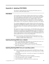
...; Copyright IBM Corp. 2004 29 Locate Downloadable files for using a flash update diskette or by starting bootable CD image (known as flash memory). BIOS by category, click BIOS. 5. Updating POST/BIOS This appendix contains information about updating POST/BIOS and how to support systems without ...system (BIOS) code, and the IBM Setup Utility program. Your computer system board has a module called electrically erasable programmable read-only memory (EEPROM, also referred to the IBM Web site, Web page content (including the links referenced in the following procedure) is built into...
...; Copyright IBM Corp. 2004 29 Locate Downloadable files for using a flash update diskette or by starting bootable CD image (known as flash memory). BIOS by category, click BIOS. 5. Updating POST/BIOS This appendix contains information about updating POST/BIOS and how to support systems without ...system (BIOS) code, and the IBM Setup Utility program. Your computer system board has a module called electrically erasable programmable read-only memory (EEPROM, also referred to the IBM Web site, Web page content (including the links referenced in the following procedure) is built into...
User Manual
Page 47
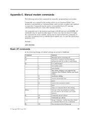
... +++ H_ H0 Function Manually answer incoming call. Commands are not echoed Commands are accepted by the modem while it is in the modem non-volatile memory. Commands are echoed Escape Characters - Example: ATH [ENTER] Basic AT commands In the following section lists commands for five seconds of silence flash return to...
... +++ H_ H0 Function Manually answer incoming call. Commands are not echoed Commands are accepted by the modem while it is in the modem non-volatile memory. Commands are echoed Escape Characters - Example: ATH [ENTER] Basic AT commands In the following section lists commands for five seconds of silence flash return to...
User Manual
Page 48
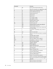
... Guide Function Force modem off-hook (make busy) Note: H1 command is not supported for Italy Display product-identification code Factory ROM checksum test Internal memory test Firmware ID Reserved ID Low speaker volume Low speaker volume Medium speaker volume High speaker volume Internal speaker off Internal speaker on until carrier...
... Guide Function Force modem off-hook (make busy) Note: H1 command is not supported for Italy Display product-identification code Factory ROM checksum test Internal memory test Firmware ID Reserved ID Low speaker volume Low speaker volume Medium speaker volume High speaker volume Internal speaker off Internal speaker on until carrier...
User Manual
Page 57
...11 cover closing 24 lock 20 opening 12 D device drivers 11 DIMMs 16 diskette drive, removing and replacing 20 double data rate (DDR) memory 16 drives installing 14 E environment, operating 6 error startup sequence 28 Ethernet 2 exiting Setup Utility 25 expansion adapters 3 external options 9 &#... Setup Utility 25 information resources 1 input/output (I/O) features 3 installing options adapters 17 cable lock 20 drives 14 memory 16 internal drives 2 L locating components 13 M memory installing 16 removing and replacing 16 type 2 microprocessor type 2 modem commands Basic AT 33 Extended AT 35 Fax ...
...11 cover closing 24 lock 20 opening 12 D device drivers 11 DIMMs 16 diskette drive, removing and replacing 20 double data rate (DDR) memory 16 drives installing 14 E environment, operating 6 error startup sequence 28 Ethernet 2 exiting Setup Utility 25 expansion adapters 3 external options 9 &#... Setup Utility 25 information resources 1 input/output (I/O) features 3 installing options adapters 17 cable lock 20 drives 14 memory 16 internal drives 2 L locating components 13 M memory installing 16 removing and replacing 16 type 2 microprocessor type 2 modem commands Basic AT 33 Extended AT 35 Fax ...
User Manual
Page 58
...features 3 primary startup sequence 28 R recovering from a POST/BIOS update failure 30 removing and replacing adapters 17 battery 18 diskette drive 20 memory 16 optical drive 19 riser card 17 S security cable lock 20 features 3 hard disk drive 25 profile by device 27 selecting startup ...28 temporary startup device 28 software 4 specifications 6 startup sequence 28 system board components, accessing 14 connectors 15 identifying parts 15 location 15 memory 5, 16 system management 2 U updating BIOS diskette 29 OS 29 updating POST/BIOS 29 using IBM Setup Utility 25 passwords 25 security profile...
...features 3 primary startup sequence 28 R recovering from a POST/BIOS update failure 30 removing and replacing adapters 17 battery 18 diskette drive 20 memory 16 optical drive 19 riser card 17 S security cable lock 20 features 3 hard disk drive 25 profile by device 27 selecting startup ...28 temporary startup device 28 software 4 specifications 6 startup sequence 28 system board components, accessing 14 connectors 15 identifying parts 15 location 15 memory 5, 16 system management 2 U updating BIOS diskette 29 OS 29 updating POST/BIOS 29 using IBM Setup Utility 25 passwords 25 security profile...


