User Manual
Page 5
...30 Appendix B. Updating POST/BIOS . . . 29 POST/BIOS 29 Updating (flashing) BIOS from a diskette . . . . 29 Updating (flashing) BIOS from your computer 11 Obtaining device drivers 11 Opening the cover 12 Locating components 13 Accessing system board components and drives . . 14 Identifying parts on the rear of... your computer 10 Locating connectors on the system board . . . . . 15 Installing memory 16 Installing PCI adapters 17 Removing and replacing ...
...30 Appendix B. Updating POST/BIOS . . . 29 POST/BIOS 29 Updating (flashing) BIOS from a diskette . . . . 29 Updating (flashing) BIOS from your computer 11 Obtaining device drivers 11 Opening the cover 12 Locating components 13 Accessing system board components and drives . . 14 Identifying parts on the rear of... your computer 10 Locating connectors on the system board . . . . . 15 Installing memory 16 Installing PCI adapters 17 Removing and replacing ...
User Manual
Page 7
... condition of smoke or sparks vent from the power source and telecommunication lines until it repaired, if necessary. However, personal computers are developed to diagnose the situation yourself. By carefully following the information contained in a safe and controlled manner. Contact the... serious enough that an internal electronic component has failed in this document carefully. Note: This information includes references to your computer and its components for further guidance. Or, they might hear sounds like popping, cracking or hissing. The information in ...
... condition of smoke or sparks vent from the power source and telecommunication lines until it repaired, if necessary. However, personal computers are developed to diagnose the situation yourself. By carefully following the information contained in a safe and controlled manner. Contact the... serious enough that an internal electronic component has failed in this document carefully. Note: This information includes references to your computer and its components for further guidance. Or, they might hear sounds like popping, cracking or hissing. The information in ...
User Manual
Page 8
v The computer product, the power cord or power adapter has been exposed to reduce the risk of injury and property damage. Note: If you can cause the ... these conditions with a non-IBM product (such as an extension cord), stop using that liquid has been spilled or an object has fallen onto the computer product, the power cord or power adapter. Use only an IBM authorized service provider who is appropriate for further instructions, or until you attempt the...
v The computer product, the power cord or power adapter has been exposed to reduce the risk of injury and property damage. Note: If you can cause the ... these conditions with a non-IBM product (such as an extension cord), stop using that liquid has been spilled or an object has fallen onto the computer product, the power cord or power adapter. Use only an IBM authorized service provider who is appropriate for further instructions, or until you attempt the...
User Manual
Page 9
... replace the outlet with one that enables this safety feature by a qualified electrician. Batteries supplied by IBM for use with your computer equipment appears to use with your product have been damaged in any battery. If power strips are rated to handle the electrical requirements.../or shows signs of the branch circuit rating. Connect and disconnect the equipment from the electrical outlet carefully Batteries All IBM personal computers contain a non-rechargeable coin cell battery to provide power to water or other liquids. Never attempt to provide system power when ...
... replace the outlet with one that enables this safety feature by a qualified electrician. Batteries supplied by IBM for use with your computer equipment appears to use with your product have been damaged in any battery. If power strips are rated to handle the electrical requirements.../or shows signs of the branch circuit rating. Connect and disconnect the equipment from the electrical outlet carefully Batteries All IBM personal computers contain a non-rechargeable coin cell battery to provide power to water or other liquids. Never attempt to provide system power when ...
User Manual
Page 10
...For some heat during an electrical storm. v Ventilation slots, fans and/or heat sinks are left unused for an extended period when the computer is functioning or when the battery is charging. v Do not operate your battery is possible for safety, comfort, and reliable operation. Never.../DVD discs from the battery manufacturer. Do not let rechargeable Lithium-Ion batteries completely discharge or store these features. Heat and product ventilation Computers generate heat when turned on a bed, sofa, carpet, or other flexible surface. Do not use v Do not bend or flex CD...
...For some heat during an electrical storm. v Ventilation slots, fans and/or heat sinks are left unused for an extended period when the computer is functioning or when the battery is charging. v Do not operate your battery is possible for safety, comfort, and reliable operation. Never.../DVD discs from the battery manufacturer. Do not let rechargeable Lithium-Ion batteries completely discharge or store these features. Heat and product ventilation Computers generate heat when turned on a bed, sofa, carpet, or other flexible surface. Do not use v Do not bend or flex CD...

User Manual
Page 15
... along with your computer provides information for setting up -to-date manuals for installing external and internal options are available from the World Wide Web. Your computer incorporates many of the latest advances in computer technology and can be upgraded as your computer. Access IBM provides... a link to : http://www.ibm.com/pc/support Type your computer are included in the Quick Path field,...
... along with your computer provides information for setting up -to-date manuals for installing external and internal options are available from the World Wide Web. Your computer incorporates many of the latest advances in computer technology and can be upgraded as your computer. Access IBM provides... a link to : http://www.ibm.com/pc/support Type your computer are included in the Quick Path field,...
User Manual
Page 16
... supports the Wake on page 25. Features 2 User Guide This section provides an overview of models. System summary The following information covers a variety of the computer features and preinstalled software.
... supports the Wake on page 25. Features 2 User Guide This section provides an overview of models. System summary The following information covers a variety of the computer features and preinstalled software.

User Manual
Page 18
v Startup without diskette drive, keyboard, or mouse v Diskette and hard disk I/O control v Serial and parallel port I/O control v Security profile by device IBM preinstalled software Your computer comes with preinstalled software. An operating system, device drivers to support built-in features, and other support programs are included. 4 User Guide
v Startup without diskette drive, keyboard, or mouse v Diskette and hard disk I/O control v Serial and parallel port I/O control v Security profile by device IBM preinstalled software Your computer comes with preinstalled software. An operating system, device drivers to support built-in features, and other support programs are included. 4 User Guide
User Manual
Page 20
...in British thermal units (Btu) per hour: Minimum configuration: 205.8 Btu/hr (60 watts) Acoustical noise-emission values Note: In this computer, fan speed is controlled by the American National Standards Institute (ANSI) S12.10 and ISO 7779 and are reported in accordance with a ...ft): Idle: 26 dBA Operating: 29 dBA Declared (upper limit) sound-power levels: Idle: 4.0 bels Operating: 4.3 bels Average sound-pressure levels for your computer model and type at: http://www.ibm.com/pc/support/ Dimensions Airflow Width: 12.2 inches (310 mm) Height: 3.35 inches (85 mm) Approximately ...
...in British thermal units (Btu) per hour: Minimum configuration: 205.8 Btu/hr (60 watts) Acoustical noise-emission values Note: In this computer, fan speed is controlled by the American National Standards Institute (ANSI) S12.10 and ISO 7779 and are reported in accordance with a ...ft): Idle: 26 dBA Operating: 29 dBA Declared (upper limit) sound-power levels: Idle: 4.0 bels Operating: 4.3 bels Average sound-pressure levels for your computer model and type at: http://www.ibm.com/pc/support/ Dimensions Airflow Width: 12.2 inches (310 mm) Height: 3.35 inches (85 mm) Approximately ...
User Manual
Page 21
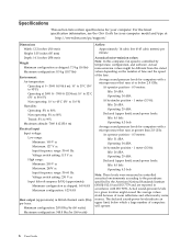
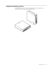
Overview 7 Supported operating positions To provide proper air flow to internal components, you must position your computer in one of the positions as illustrated below. Chapter 1.
Overview 7 Supported operating positions To provide proper air flow to internal components, you must position your computer in one of the positions as illustrated below. Chapter 1.

User Manual
Page 23
...protective package containing the option to do not open the static-protective package containing the option until you handle options and other computer components, take these instructions along with the instructions that are instructed to a metal expansion-slot cover or other metal surface...on it directly in addition to build up around you install or remove any option, read "Important safety information" on the computer for installing optional memory, PCI adapters, drives, and security features. Installing options This chapter provides instructions for at least two ...
...protective package containing the option to do not open the static-protective package containing the option until you handle options and other computer components, take these instructions along with the instructions that are instructed to a metal expansion-slot cover or other metal surface...on it directly in addition to build up around you install or remove any option, read "Important safety information" on the computer for installing optional memory, PCI adapters, drives, and security features. Installing options This chapter provides instructions for at least two ...
User Manual
Page 24
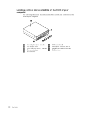
Locating controls and connectors on the front of your computer The following illustration shows locations of the controls and connectors on the front of your computer. 1 Cover keylock (some models) 6 USB connectors (2) 2 CD or DVD drive 7 Microphone connector (line in) 3 Hard disk drive activity indicator 8 Headphone connector (line out) 4 Power-on indicator 9 Diskette drive 5 Power button 10 User Guide
Locating controls and connectors on the front of your computer The following illustration shows locations of the controls and connectors on the front of your computer. 1 Cover keylock (some models) 6 USB connectors (2) 2 CD or DVD drive 7 Microphone connector (line in) 3 Hard disk drive activity indicator 8 Headphone connector (line out) 4 Power-on indicator 9 Diskette drive 5 Power button 10 User Guide
User Manual
Page 25
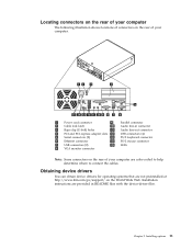
... following illustration shows locations of connectors on the rear of your computer. 1 Power cord connector 9 Parallel connector 2 Cable lock latch 10 Audio line-in README files with the device-driver files. Installing options 11 Chapter 2. Obtaining device ...drivers You can obtain device drivers for operating systems that are not preinstalled at http://www.ibm.com/pc/support/ on the rear of your computer are provided in connector 3 Rope clip (U-bolt) holes 11 Audio line-out connector 4 PCI and PCI express adapter slots 12 USB connectors (4) 5 Serial connectors (2) 13...
... following illustration shows locations of connectors on the rear of your computer. 1 Power cord connector 9 Parallel connector 2 Cable lock latch 10 Audio line-in README files with the device-driver files. Installing options 11 Chapter 2. Obtaining device ...drivers You can obtain device drivers for operating systems that are not preinstalled at http://www.ibm.com/pc/support/ on the rear of your computer are provided in connector 3 Rope clip (U-bolt) holes 11 Audio line-out connector 4 PCI and PCI express adapter slots 12 USB connectors (4) 5 Serial connectors (2) 13...
User Manual
Page 26
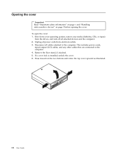
Unplug all attached devices and the computer. 2. This includes power cords, input/output (I/O) cables, and any media (diskettes, CDs, or tapes) from the drives, and turn off all power cords from electrical ... as illustrated. 12 User Guide Remove the floor stand, if attached. 5. Shut down your operating system, remove any other cables that are connected to the computer. To open the cover: 1. Disconnect all cables attached to the...
Unplug all attached devices and the computer. 2. This includes power cords, input/output (I/O) cables, and any media (diskettes, CDs, or tapes) from the drives, and turn off all power cords from electrical ... as illustrated. 12 User Guide Remove the floor stand, if attached. 5. Shut down your operating system, remove any other cables that are connected to the computer. To open the cover: 1. Disconnect all cables attached to the...
User Manual
Page 27
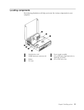
Locating components The following illustration will help you locate the various components in your computer. 1 Diskette drive lock 2 DIMM (memory) connectors (2) 3 Battery 4 PCI riser 5 Power supply assembly 6 CD or DVD drive (hard disk drive is under the CD drive) 7 CD or DVD drive lock Chapter 2. Installing options 13
Locating components The following illustration will help you locate the various components in your computer. 1 Diskette drive lock 2 DIMM (memory) connectors (2) 3 Battery 4 PCI riser 5 Power supply assembly 6 CD or DVD drive (hard disk drive is under the CD drive) 7 CD or DVD drive lock Chapter 2. Installing options 13
User Manual
Page 28
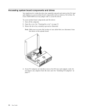
... jumper and to access system board components such as illustrated. Do not remove any adapters from the drives or the system board. 4. Turn off the computer. 2. Note: Make sure you note the location of any PCI adapters are installed, remove the PCI riser and adapter cards. If any cables that you...
... jumper and to access system board components such as illustrated. Do not remove any adapters from the drives or the system board. 4. Turn off the computer. 2. Note: Make sure you note the location of any PCI adapters are installed, remove the PCI riser and adapter cards. If any cables that you...
User Manual
Page 29
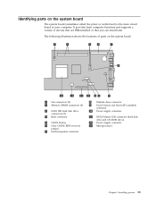
... and supports a variety of parts on the system board The system board (sometimes called the planar or motherboard) is the main circuit board in your computer. The following illustration shows the locations of devices that are IBM-installed or that you can install later. Identifying parts on the system board. 1 Fan...
... and supports a variety of parts on the system board The system board (sometimes called the planar or motherboard) is the main circuit board in your computer. The following illustration shows the locations of devices that are IBM-installed or that you can install later. Identifying parts on the system board. 1 Fan...
User Manual
Page 30
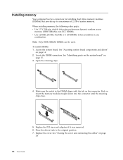
To install DIMMs: 1. Open the retaining clips. 4. Installing memory Your computer has two connectors for installing dual inline memory modules (DIMMs) that provide up to the original position. 7. Access the system board. See "Accessing system board ...
To install DIMMs: 1. Open the retaining clips. 4. Installing memory Your computer has two connectors for installing dual inline memory modules (DIMMs) that provide up to the original position. 7. Access the system board. See "Accessing system board ...
User Manual
Page 31
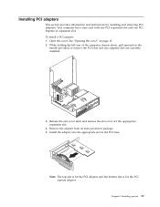
To install a PCI adapter: 1. While holding the left rear of the computer chassis down, pull upward on page 12. 2. Installing PCI adapters This section provides information and instructions for the appropriate expansion slot. 4. Open the cover. Release ... latch and remove the slot cover for installing and removing PCI adapters. Chapter 2. Install the adapter into the appropriate slot in the PCI riser. Your computer has a riser card with one PCI expansion slot and one PCI Express x1 expansion slot. See "Opening the cover" on the handle provided, to remove...
To install a PCI adapter: 1. While holding the left rear of the computer chassis down, pull upward on page 12. 2. Installing PCI adapters This section provides information and instructions for the appropriate expansion slot. 4. Open the cover. Release ... latch and remove the slot cover for installing and removing PCI adapters. Chapter 2. Install the adapter into the appropriate slot in the PCI riser. Your computer has a riser card with one PCI expansion slot and one PCI Express x1 expansion slot. See "Opening the cover" on the handle provided, to remove...

User Manual
Page 32
...complete the installation, go to "Closing the cover and connecting the cables" on page 15 and locate the battery. 4. Turn off the computer. Remove the PCI riser and PCI adapters that maintains the date, time, and settings for information about replacing and disposing of memory that...work safely. A battery, sometimes called the CMOS battery, keeps this information active when you turn off the computer and disconnect the power cord from the electrical outlet and from the computer. 2. An error message is displayed when you turn on page v. To change the battery: 1. These ...
...complete the installation, go to "Closing the cover and connecting the cables" on page 15 and locate the battery. 4. Turn off the computer. Remove the PCI riser and PCI adapters that maintains the date, time, and settings for information about replacing and disposing of memory that...work safely. A battery, sometimes called the CMOS battery, keeps this information active when you turn off the computer and disconnect the power cord from the electrical outlet and from the computer. 2. An error message is displayed when you turn on page v. To change the battery: 1. These ...


