User Manual
Page 3
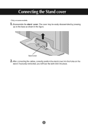
Disassemble the stand cover. After connecting the cables, correctly position the stand cover into place. 2 Stand cover 2. If securely connected, you will hear the latch click into the holes on the base as shown in the figure. The cover may be easily disassembled by pressing up on the stand. Only on some models. 1. Connecting the Stand cover -
Disassemble the stand cover. After connecting the cables, correctly position the stand cover into place. 2 Stand cover 2. If securely connected, you will hear the latch click into the holes on the base as shown in the figure. The cover may be easily disassembled by pressing up on the stand. Only on some models. 1. Connecting the Stand cover -
User Manual
Page 4
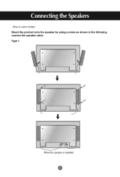
Only on some models. Type 1 When the speaker is installed. 3 Connecting the Speakers - Mount the product onto the speaker by using a screw as shown in the following connect the speaker cable.
Only on some models. Type 1 When the speaker is installed. 3 Connecting the Speakers - Mount the product onto the speaker by using a screw as shown in the following connect the speaker cable.
User Manual
Page 5
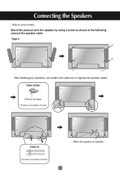
Type 2 After installing your speakers, use holders and cable ties to organize the speaker cables. Cable holder Remove the paper. * This feature is installed. Only on some models. Mount the product onto the speaker by using a screw as shown in all model. Cable tie * This feature is not available in all model. 4 When the speaker is not available in the following connect the speaker cable. Connecting the Speakers -
Type 2 After installing your speakers, use holders and cable ties to organize the speaker cables. Cable holder Remove the paper. * This feature is installed. Only on some models. Mount the product onto the speaker by using a screw as shown in all model. Cable tie * This feature is not available in all model. 4 When the speaker is not available in the following connect the speaker cable. Connecting the Speakers -

User Manual
Page 7
.../OUT Power Connector : Connect the power cord Wired Remote Control Port RS-232C Serial Ports RGB, HDMI/DVI Ports PC Sound Jack : Connect the audio cable to the *LINE OUT jack of the program (Refer to the speaker including a built-in the user's guide could be different from the actual image...
.../OUT Power Connector : Connect the power cord Wired Remote Control Port RS-232C Serial Ports RGB, HDMI/DVI Ports PC Sound Jack : Connect the audio cable to the *LINE OUT jack of the program (Refer to the speaker including a built-in the user's guide could be different from the actual image...
User Manual
Page 8
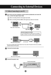
...A When connecting with ferrite cores to maintain standard compliance for the product. PC * User must use shielded signal interface cables (D-sub 15 pin cable, DVI cable) with the D-Sub signal input cable. PC MAC PC/MAC Macintosh Adapter (not included) Use the standard Macintosh adapter since an incompatible adapter is available in ... side of all, see if the computer, product and the peripherals are turned off. Rear side of the product. Then, connect the signal input cable. Connect the Audio cable. Connect the power cord. B When connecting with the HDMI to DVI signal input...
...A When connecting with ferrite cores to maintain standard compliance for the product. PC * User must use shielded signal interface cables (D-sub 15 pin cable, DVI cable) with the D-Sub signal input cable. PC MAC PC/MAC Macintosh Adapter (not included) Use the standard Macintosh adapter since an incompatible adapter is available in ... side of all, see if the computer, product and the peripherals are turned off. Rear side of the product. Then, connect the signal input cable. Connect the Audio cable. Connect the power cord. B When connecting with the HDMI to DVI signal input...

User Manual
Page 9
...PC : 15-pin D-Sub analog signal. Press the INPUT button on the PC. INPUT AUTO/SET Power button Select an input signal. Connect the signal cables (HDMI to DVI and D-Sub) to a grounded power outlet or power strip (three prong connector.) 8 INPUT AUTO/SET A When connecting with a ...HDMI to DVI signal input cable. • Select HDMI/DVI : HDMI to select the input signal. Input AV Component1 Component2 RGB PC HDMI/DVI Input AV Component1 Component2 RGB PC HDMI...
...PC : 15-pin D-Sub analog signal. Press the INPUT button on the PC. INPUT AUTO/SET Power button Select an input signal. Connect the signal cables (HDMI to DVI and D-Sub) to a grounded power outlet or power strip (three prong connector.) 8 INPUT AUTO/SET A When connecting with a ...HDMI to DVI signal input cable. • Select HDMI/DVI : HDMI to select the input signal. Input AV Component1 Component2 RGB PC HDMI/DVI Input AV Component1 Component2 RGB PC HDMI...
User Manual
Page 10
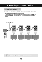
... of a PC to the RGB IN connector of other product. • To use cable distributor. 9 We recommend that you should use different products connected to each other Connect one end of the signal input cable(15-pin D-Sub Signal Cable) to the RGB OUT connector of product 1 and connect the other end to... the other products. 15-pin D-Sub Signal Cable RGB IN RGB OUT RGB IN RGB OUT RGB IN RGB OUT RGB IN RGB OUT PC PC Product 1 Product 2 Product 3 Product 4 Note • When ...
... of a PC to the RGB IN connector of other product. • To use cable distributor. 9 We recommend that you should use different products connected to each other Connect one end of the signal input cable(15-pin D-Sub Signal Cable) to the RGB OUT connector of product 1 and connect the other end to... the other products. 15-pin D-Sub Signal Cable RGB IN RGB OUT RGB IN RGB OUT RGB IN RGB OUT RGB IN RGB OUT PC PC Product 1 Product 2 Product 3 Product 4 Note • When ...
User Manual
Page 11
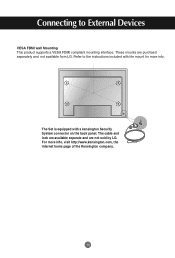
Refer to External Devices VESA FDMI wall Mounting This product supports a VESA FDMI compliant mounting interface. The cable and lock are available separate and are purchaed separately and not available from LG. For more info. Connecting to the instructions included with a kensington Securify System connector on the back panel. These mounts are not sold by LG. The Set is equipped with hte mount for more info, visit http://www.kensington.com, the internet home page of the Kensington company. 10
Refer to External Devices VESA FDMI wall Mounting This product supports a VESA FDMI compliant mounting interface. The cable and lock are available separate and are purchaed separately and not available from LG. For more info. Connecting to the instructions included with a kensington Securify System connector on the back panel. These mounts are not sold by LG. The Set is equipped with hte mount for more info, visit http://www.kensington.com, the internet home page of the Kensington company. 10

User Manual
Page 13
...on the remote control to select the input signal. B When connecting with a S-Video cable. • Connect to the S-Video input terminal to External Devices Video Input Connect the video cable as shown in the below figure and then connect the power cord (See page 7).... Product IN OUT Product IN OUT Audio Cable (not included) BNC Cable (not included) Audio Cable (not included) S-Video Cable (not included) VCR/DVD Receiver VCR/DVD Receiver Select an input signal. INPUT AUTO/SET A When connecting with S-Video cable, S-Video input has a priority. 12 Connecting...
...on the remote control to select the input signal. B When connecting with a S-Video cable. • Connect to the S-Video input terminal to External Devices Video Input Connect the video cable as shown in the below figure and then connect the power cord (See page 7).... Product IN OUT Product IN OUT Audio Cable (not included) BNC Cable (not included) Audio Cable (not included) S-Video Cable (not included) VCR/DVD Receiver VCR/DVD Receiver Select an input signal. INPUT AUTO/SET A When connecting with S-Video cable, S-Video input has a priority. 12 Connecting...

User Manual
Page 14
Press the INPUT button on the bottom of the product. Product A M Product B M BNC Cable Audio Cable (not included) (not included) BNC Cable Audio Cable (not included) (not included) HDTV Receiver HDTV Receiver Note - Select an input signal. Component doesn't support HDCP. INPUT AUTO/SET A • Select...Some devices may require HDCP in order to External Devices Component Input (480i/480p/576i/576p/720p/1080i) Connect the video/audio cable as shown in the below figure and then, connect the power cord (See page 7). • Connect the input terminal with a proper...
Press the INPUT button on the bottom of the product. Product A M Product B M BNC Cable Audio Cable (not included) (not included) BNC Cable Audio Cable (not included) (not included) HDTV Receiver HDTV Receiver Note - Select an input signal. Component doesn't support HDCP. INPUT AUTO/SET A • Select...Some devices may require HDCP in order to External Devices Component Input (480i/480p/576i/576p/720p/1080i) Connect the video/audio cable as shown in the below figure and then, connect the power cord (See page 7). • Connect the input terminal with a proper...

User Manual
Page 15
... the power cord (See page 7). INPUT SET Or, press the INPUT botton on the remote control to DVI signal input cable. INPUT AUTO/SET When connecting with a HDMI signal input cable. • Select HDMI/DVI Input AV Component1 Component2 RGB PC HDMI/DVI 14 Connect the video/audio... (480p/576p/720p/1080i/1080p) -HDMI Supports High Definition input and HDCP (High-bandwidth Digital Content Protection). Connecting to DVI Signal Cable (not included) RCA-PC Audio Cable HDMI Signal Cable (not included) VCR/DVD/Set-top Box VCR/DVD/Set-top Box Note : Dolby Digital is not supported.
... the power cord (See page 7). INPUT SET Or, press the INPUT botton on the remote control to DVI signal input cable. INPUT AUTO/SET When connecting with a HDMI signal input cable. • Select HDMI/DVI Input AV Component1 Component2 RGB PC HDMI/DVI 14 Connect the video/audio... (480p/576p/720p/1080i/1080p) -HDMI Supports High Definition input and HDCP (High-bandwidth Digital Content Protection). Connecting to DVI Signal Cable (not included) RCA-PC Audio Cable HDMI Signal Cable (not included) VCR/DVD/Set-top Box VCR/DVD/Set-top Box Note : Dolby Digital is not supported.
User Manual
Page 16
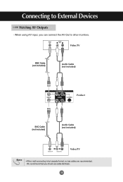
Connecting to other monitors. Video/TV BNC Cable (not included) Audio Cable (not included) IN Product OUT BNC Cable (not included) Audio Cable (not included) Video/TV Note • When multi-connecting in/out cascade format, no loss cables are recommended. We recommend that you can connect the AV Out to External Devices Watching AV Outputs - When using AV input, you should use cable distributor. 15
Connecting to other monitors. Video/TV BNC Cable (not included) Audio Cable (not included) IN Product OUT BNC Cable (not included) Audio Cable (not included) Video/TV Note • When multi-connecting in/out cascade format, no loss cables are recommended. We recommend that you can connect the AV Out to External Devices Watching AV Outputs - When using AV input, you should use cable distributor. 15

User Manual
Page 33
...The 'Controls Locked' message appears when pressing the Menu button. the screen appears extremely dark. • Backlight may need service. Check the signal cable. • Press the 'INPUT' menu in this manual. * Maximum resolution RGB : 1600 x 1200 @60Hz HDMI/DVI : 1920 x 1080 @60Hz G... Does the 'Check signal cable' message • The signal cable between PC and product is blue but • Adjust brightness and contrast again. G Power is on . • The signal from the web...
...The 'Controls Locked' message appears when pressing the Menu button. the screen appears extremely dark. • Backlight may need service. Check the signal cable. • Press the 'INPUT' menu in this manual. * Maximum resolution RGB : 1600 x 1200 @60Hz HDMI/DVI : 1920 x 1080 @60Hz G... Does the 'Check signal cable' message • The signal cable between PC and product is blue but • Adjust brightness and contrast again. G Power is on . • The signal from the web...

User Manual
Page 34
... signal. G Horizontal noise appears or the characters look blurred. • D-Sub analog signal - G Is the screen position wrong? • D-Sub analog signal - Connect the signal cable that fits into the current mode. Setting menu.
... signal. G Horizontal noise appears or the characters look blurred. • D-Sub analog signal - G Is the screen position wrong? • D-Sub analog signal - Connect the signal cable that fits into the current mode. Setting menu.
User Manual
Page 35
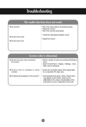
...on the screen, which can be attributable to more than 24 bits (true color) Select Control Panel - G No sound? • See if the audio cable is connected properly. • Adjust the volume. • See if the sound is too low. • Select the appropriate equalize sound. • ...of colors to the unique characteristics of the LCD. 34 G Screen has poor color resolution (16 colors). • Set the number of the signal cable. Or, re-insert the PC video card. G Sound is set properly. Troubleshooting The audio function does not work. Color Table menu in Windows. G...
...on the screen, which can be attributable to more than 24 bits (true color) Select Control Panel - G No sound? • See if the audio cable is connected properly. • Adjust the volume. • See if the sound is too low. • Select the appropriate equalize sound. • ...of colors to the unique characteristics of the LCD. 34 G Screen has poor color resolution (16 colors). • Set the number of the signal cable. Or, re-insert the PC video card. G Sound is set properly. Troubleshooting The audio function does not work. Color Table menu in Windows. G...
User Manual
Page 40
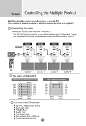
... the product on/off, select an input source or adjust the OSD menu from your PC. RS-232C Cable (not included) PC monitor 1 monitor 2 monitor 3 monitor 4 RS-232C Configurations 7-Wire Configurations (Standard RS-232C cable) PC RXD 2 TXD 3 GND 5 DTR 4 DSR 6 RTS 7 CTS 8 Monitor 3 2 5 6 4 8 7 ... 8bits Parity Bit : None Stop Bit : 1bit Flow Control : None Communication Code : ASCII code Use a crossed (reverse) cable A1 Connecting the cable Connect the RS-232C cable as shown in the picture. * The RS-232C protocol is used for communication between the PC and product. RS-232C Controlling...
... the product on/off, select an input source or adjust the OSD menu from your PC. RS-232C Cable (not included) PC monitor 1 monitor 2 monitor 3 monitor 4 RS-232C Configurations 7-Wire Configurations (Standard RS-232C cable) PC RXD 2 TXD 3 GND 5 DTR 4 DSR 6 RTS 7 CTS 8 Monitor 3 2 5 6 4 8 7 ... 8bits Parity Bit : None Stop Bit : 1bit Flow Control : None Communication Code : ASCII code Use a crossed (reverse) cable A1 Connecting the cable Connect the RS-232C cable as shown in the picture. * The RS-232C protocol is used for communication between the PC and product. RS-232C Controlling...


