
Owner's Manual
Page 1
ENGLISH LCD TV PLASMA TV OWNER'S MANUAL LCD TV MODELS 32LB5R* 37LB5R* 42LB5R* 47LB5R* 52LB5R* PLASMA TV MODELS 42PB4R* 50PB4R* Please read this information To your TV Retain it for all models. (47LB5R*/52LB5R* only) This feature is not available for future reference. Refer to the label on the back cover and quote this manual carefully before operating your dealer when requiring service. Record model number and serial number of the TV.
ENGLISH LCD TV PLASMA TV OWNER'S MANUAL LCD TV MODELS 32LB5R* 37LB5R* 42LB5R* 47LB5R* 52LB5R* PLASMA TV MODELS 42PB4R* 50PB4R* Please read this information To your TV Retain it for all models. (47LB5R*/52LB5R* only) This feature is not available for future reference. Refer to the label on the back cover and quote this manual carefully before operating your dealer when requiring service. Record model number and serial number of the TV.

Owner's Manual
Page 3
...PIP PSRIM-PLINK PIP PIP PR+ INPUTTINVPUT POWER BRIGHT DVD SWTAEP XT PIP I/II INPUT VCR TMVODE SHTIFIMTE MENU LIST MACTHIMINEE OK LIVE TV EXIT VOL MARFKAV/ SHTIFIMTE 1 4 MUTE 2 PR 7 5 3 SHTIFIMTE MENU LIST RATIO PIP PSRIM-PLINK PIP PIP PR+ ...INPUTTINVPUT POWER BRIGHT SWTAEP XT PIP I/II INPUT VCR DVD TMVODE MACTHIMINEE LIVE TV EEP 8 6 OK EXIT 0 9 SITION Q.VIEW INDEX REVEAL ? 1 4 VOL MARFKAV/ MUTE PR 2 SHTIFIMTE 7 SLEEP 5 8 3 6 SIZE 0 TIME POSITION ...
...PIP PSRIM-PLINK PIP PIP PR+ INPUTTINVPUT POWER BRIGHT DVD SWTAEP XT PIP I/II INPUT VCR TMVODE SHTIFIMTE MENU LIST MACTHIMINEE OK LIVE TV EXIT VOL MARFKAV/ SHTIFIMTE 1 4 MUTE 2 PR 7 5 3 SHTIFIMTE MENU LIST RATIO PIP PSRIM-PLINK PIP PIP PR+ ...INPUTTINVPUT POWER BRIGHT SWTAEP XT PIP I/II INPUT VCR DVD TMVODE MACTHIMINEE LIVE TV EEP 8 6 OK EXIT 0 9 SITION Q.VIEW INDEX REVEAL ? 1 4 VOL MARFKAV/ MUTE PR 2 SHTIFIMTE 7 SLEEP 5 8 3 6 SIZE 0 TIME POSITION ...

Owner's Manual
Page 4
... Menu 4 Front Panel Controls 5 Back Panel Information 7 Stand Installation 9 Attaching the TV to a Wall 10 Back Cover for PC Mode 30 WATCHING TV / PROGRAMME CONTROL Remote Control Key Functions 34 Turning on the TV 36 Programme Selection 36 Volume Adjustment 36 On Screen Menus Selection and Adjustment ......37 Auto...44 Calling the Programme List 45 Input Source Selection 46 Key lock 47 48 TIME MACHINE TimeShift Mode(Pause & Replay of Live TV)...... 50 Format hard disk 53 Instant Recording 54 Manual Record 56 Schedule List 57 Record Quality 57 To use the USB device 58...
... Menu 4 Front Panel Controls 5 Back Panel Information 7 Stand Installation 9 Attaching the TV to a Wall 10 Back Cover for PC Mode 30 WATCHING TV / PROGRAMME CONTROL Remote Control Key Functions 34 Turning on the TV 36 Programme Selection 36 Volume Adjustment 36 On Screen Menus Selection and Adjustment ......37 Auto...44 Calling the Programme List 45 Input Source Selection 46 Key lock 47 48 TIME MACHINE TimeShift Mode(Pause & Replay of Live TV)...... 50 Format hard disk 53 Instant Recording 54 Manual Record 56 Schedule List 57 Record Quality 57 To use the USB device 58...
Owner's Manual
Page 5
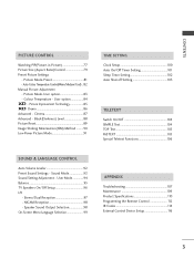
... Specifications 110 Programming the Remote Control 112 IR Codes 114 External Control Device Setup 116 3 Picture Mode-User option 83 - User Mode 94 Balance 95 TV Speakers On/Off Setup 96 I/II - CONTENTS PICCTTUURREECCOONNTTROROL L Watching PIP(Picture-in-Picture 77 Picture Size (Aspect Ratio)Control 79 Preset Picture Settings - NICAM Reception...
... Specifications 110 Programming the Remote Control 112 IR Codes 114 External Control Device Setup 116 3 Picture Mode-User option 83 - User Mode 94 Balance 95 TV Speakers On/Off Setup 96 I/II - CONTENTS PICCTTUURREECCOONNTTROROL L Watching PIP(Picture-in-Picture 77 Picture Size (Aspect Ratio)Control 79 Preset Picture Settings - NICAM Reception...
Owner's Manual
Page 6
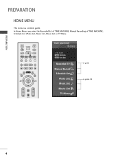
In Home Menu, you enter the Recorded list of TIME MACHINE, Manual Recording of TIME MACHINE, Schedule List ,Photo List, Music List, Movie List or TV Menu. INPUT TV INPUT POWER RATIO BRIGHT MODE TV DVD VCR SIMPLINK PIP TEXT I/II PIP PR- PIP PR+ SWAP PIP INPUT LIST MENU TIME MACHINE LIVE TV EXIT TIME OK TIME SHIFT SHIFT FAV/ MARK VOL PR MUTE TIME MACHINE Free Space HIGH NORMAL Recorded TV Manual Record Schedule List Photo List Music List Movie List TV Menu G p.50 G p.66~74 4 PREPARATION PREPARATION HOME MENU This menu is a contents guide.
In Home Menu, you enter the Recorded list of TIME MACHINE, Manual Recording of TIME MACHINE, Schedule List ,Photo List, Music List, Movie List or TV Menu. INPUT TV INPUT POWER RATIO BRIGHT MODE TV DVD VCR SIMPLINK PIP TEXT I/II PIP PR- PIP PR+ SWAP PIP INPUT LIST MENU TIME MACHINE LIVE TV EXIT TIME OK TIME SHIFT SHIFT FAV/ MARK VOL PR MUTE TIME MACHINE Free Space HIGH NORMAL Recorded TV Manual Record Schedule List Photo List Music List Movie List TV Menu G p.50 G p.66~74 4 PREPARATION PREPARATION HOME MENU This menu is a contents guide.

Owner's Manual
Page 7
...remove the film and then wipe the product with a polishing cloth. PREPARATION FRONT PANEL CONTROLS I If your TV. VOL PR POWER INPUT MENU OK VOLUME PROGRAMME 5 Plasma TV Models Remote Control Sensor INPUT MENU OK VOL PR INPUT MENU INPUT MENU OK VOL OK PR Power/Standby ...Indicator • illuminates red in standby mode. • illuminates green when the TV is switched on. • illuminates orange when the TV is a simplified...
...remove the film and then wipe the product with a polishing cloth. PREPARATION FRONT PANEL CONTROLS I If your TV. VOL PR POWER INPUT MENU OK VOLUME PROGRAMME 5 Plasma TV Models Remote Control Sensor INPUT MENU OK VOL PR INPUT MENU INPUT MENU OK VOL OK PR Power/Standby ...Indicator • illuminates red in standby mode. • illuminates green when the TV is switched on. • illuminates orange when the TV is a simplified...

Owner's Manual
Page 8
PR VOL OK MENU INPUT /I Remote Control Sensor Power/Standby Indicator • illuminates red in standby mode. • illuminates green when the TV is switched on. • illuminates orange when the TV is switched off during recording. PROGRAMME VOLUME OK MENU INPUT POWER 6 PREPARATION PREPARATION LCD TV Models Intelligent Eye Adjusts picture according to the surrounding conditions.
PR VOL OK MENU INPUT /I Remote Control Sensor Power/Standby Indicator • illuminates red in standby mode. • illuminates green when the TV is switched on. • illuminates orange when the TV is switched off during recording. PROGRAMME VOLUME OK MENU INPUT POWER 6 PREPARATION PREPARATION LCD TV Models Intelligent Eye Adjusts picture according to the surrounding conditions.
Owner's Manual
Page 9
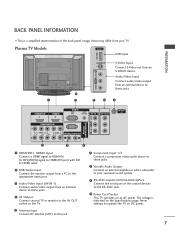
... VIDEO AV IN 1 AV OUT ANTENNA IN 6 7 8 1 HDMI/DVI1, HDMI2 Input Connect a HDMI signal to the RS-232C jack. 9 Power Cord Socket This TV operates on an AC power. Or DVI(VIDEO)signal to HDMI/DVI port with DVI to HDMI cable. 2 RGB/Audio Input Connect the monitor output... 1) Connect audio/video output from an external device to these jacks. 7 Variable Audio Output Connect an external amplifier or add a subwoofer to your TV. Image shown may differ from an S-VIDEO device. The voltage is a simplified representation of the control devices to HDMI IN. Never attempt to operate...
... VIDEO AV IN 1 AV OUT ANTENNA IN 6 7 8 1 HDMI/DVI1, HDMI2 Input Connect a HDMI signal to the RS-232C jack. 9 Power Cord Socket This TV operates on an AC power. Or DVI(VIDEO)signal to HDMI/DVI port with DVI to HDMI cable. 2 RGB/Audio Input Connect the monitor output... 1) Connect audio/video output from an external device to these jacks. 7 Variable Audio Output Connect an external amplifier or add a subwoofer to your TV. Image shown may differ from an S-VIDEO device. The voltage is a simplified representation of the control devices to HDMI IN. Never attempt to operate...

Owner's Manual
Page 10
... the Specifications page. PREPARATION USB IN PREPARATION LCD TV Models VIDEO L/MONO AUDIO R VIDEO L/MONO AUDIO R USB IN USB IN S-VIDEO S-VIDEO S-VIDEO AV IN 2 AV IN 2 VIDEO L/MONO AUDIO R USB Input S-Video Input ... sound system. 8 RS-232C Input(CONTROL&SERVICE)Port Connect the serial port of the control devices to the RS-232C jack. 4 AV Output Connect second TV or monitor to the AV OUT socket on the...
... the Specifications page. PREPARATION USB IN PREPARATION LCD TV Models VIDEO L/MONO AUDIO R VIDEO L/MONO AUDIO R USB IN USB IN S-VIDEO S-VIDEO S-VIDEO AV IN 2 AV IN 2 VIDEO L/MONO AUDIO R USB Input S-Video Input ... sound system. 8 RS-232C Input(CONTROL&SERVICE)Port Connect the serial port of the control devices to the RS-232C jack. 4 AV Output Connect second TV or monitor to the AV OUT socket on the...

Owner's Manual
Page 11
PREPARATION STAND INSTALLATION (Only 32, 37 inch LCD TV Models) 1 Carefully place the TV screen side down on a cushioned surface to protect the screen from damage. 2 Assemble the TV as shown. 3 Fix the 4 bolts securely using the holes in the back of the TV. 9
PREPARATION STAND INSTALLATION (Only 32, 37 inch LCD TV Models) 1 Carefully place the TV screen side down on a cushioned surface to protect the screen from damage. 2 Assemble the TV as shown. 3 Fix the 4 bolts securely using the holes in the back of the TV. 9

Owner's Manual
Page 12
...A The instructions shown below are even. 3 3 Use a strong cord (must purchase seperately) to the wall. This will prevent the TV from damage. Plasma TV models LCD TV models 1 1 2 2 PREPARATION 1 Use the eye-bolts or TV brackets/bolts to fix the product to the wall as shown in the picture. (If your...wall brackets with bolts (must purchase separately) to secure the TV. G To use the TV safely make sure that children do not climb or hang from the TV. Ensure that the height of it falling when pushed. NOTE G When moving the TV undo the cords first. G Use a platform or cabinet...
...A The instructions shown below are even. 3 3 Use a strong cord (must purchase seperately) to the wall. This will prevent the TV from damage. Plasma TV models LCD TV models 1 1 2 2 PREPARATION 1 Use the eye-bolts or TV brackets/bolts to fix the product to the wall as shown in the picture. (If your...wall brackets with bolts (must purchase separately) to secure the TV. G To use the TV safely make sure that children do not climb or hang from the TV. Ensure that the height of it falling when pushed. NOTE G When moving the TV undo the cords first. G Use a platform or cabinet...
Owner's Manual
Page 13
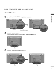
To connect additional equipment, see the External equipment Setup section. 3 Reinstall the CABLE MANAGEMENT as necessary. PREPARATION BACK COVER FOR WIRE ARRANGEMENT Plasma TV models 1 Grip the CABLE MANAGEMENT and push the cover upwards CABLE MANAGEMENT 2 Connect the cables as shown 11
To connect additional equipment, see the External equipment Setup section. 3 Reinstall the CABLE MANAGEMENT as necessary. PREPARATION BACK COVER FOR WIRE ARRANGEMENT Plasma TV models 1 Grip the CABLE MANAGEMENT and push the cover upwards CABLE MANAGEMENT 2 Connect the cables as shown 11

Owner's Manual
Page 14
To connect additional equipment, see the External equipment Setup section. 2 Reinstall the CABLE MANAGEMENT as necessary. NOTE G Do not use the CABLE MANAGEMENT to remove the cable management Hold the CABLE MANAGEMENT with both hands and pull it upward. ! If the TV is not available for all models.) CABLE MANAGEMENT How to lift the TV. - PREPARATION PREPARATION LCD TV models 1 Connect the cables as shown 3 Bundle the cables together using the supplied twister holder. (This feature is dropped, you may be injured or the TV may be damaged. 12
To connect additional equipment, see the External equipment Setup section. 2 Reinstall the CABLE MANAGEMENT as necessary. NOTE G Do not use the CABLE MANAGEMENT to remove the cable management Hold the CABLE MANAGEMENT with both hands and pull it upward. ! If the TV is not available for all models.) CABLE MANAGEMENT How to lift the TV. - PREPARATION PREPARATION LCD TV models 1 Connect the cables as shown 3 Bundle the cables together using the supplied twister holder. (This feature is dropped, you may be injured or the TV may be damaged. 12
Owner's Manual
Page 15
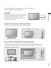
... Ensure that you connect the earth wire to telephone wires, lightening rods or gas pipes. Do not try to earth the TV by connecting it to prevent possible electric shock. If grounding methods are available from your dealer, see the optional Tilt Wall Mounting...4 inches 4 inches 4 inches 4 inches 4 inches 13 DESKTOP PEDESTAL INSTALLATION For adequate ventilation allow a clearance of 4" (10cm) all around the TV . 4 inches 4 inches R 4 inches Power Supply Circuit breaker 4 inches WALL MOUNT: HORIZONTAL INSTALLATION For adequate ventilation allow a clearance of 4" (10cm) all...
... Ensure that you connect the earth wire to telephone wires, lightening rods or gas pipes. Do not try to earth the TV by connecting it to prevent possible electric shock. If grounding methods are available from your dealer, see the optional Tilt Wall Mounting...4 inches 4 inches 4 inches 4 inches 4 inches 13 DESKTOP PEDESTAL INSTALLATION For adequate ventilation allow a clearance of 4" (10cm) all around the TV . 4 inches 4 inches R 4 inches Power Supply Circuit breaker 4 inches WALL MOUNT: HORIZONTAL INSTALLATION For adequate ventilation allow a clearance of 4" (10cm) all...
Owner's Manual
Page 16
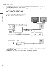
... and sound. I For optimum picture quality, adjust antenna direction. PREPARATION USB IN PREPARATION I It is recommended that 42PB4RTH / 50PB4RTH model only be split for two TVs,use an antenna signal splitter for connection. 14
... and sound. I For optimum picture quality, adjust antenna direction. PREPARATION USB IN PREPARATION I It is recommended that 42PB4RTH / 50PB4RTH model only be split for two TVs,use an antenna signal splitter for connection. 14

Owner's Manual
Page 17
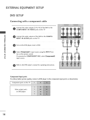
... (Y, PB, PR) of the digital set top box to the COMPONENT IN VIDEO jacks on the TV. 2 Connect the audio output of the digital set-top box to the COMPONENT IN AUDIO jacks on the TV. 1 2 VIDEO AUDIO VA COMPONENT IN AU 3 Turn on the remote control. Signal 480i/576i 480p/576p... 720p/1080i 1080p(50/60Hz) Component 1/2 Yes Yes Yes Yes HDMI1/DVI, HDMI2 No Yes Yes Yes HDMI/DVI IN 1 HDMI IN 2 15 If connected to the owner's manual for the LCD TV models...
... (Y, PB, PR) of the digital set top box to the COMPONENT IN VIDEO jacks on the TV. 2 Connect the audio output of the digital set-top box to the COMPONENT IN AUDIO jacks on the TV. 1 2 VIDEO AUDIO VA COMPONENT IN AU 3 Turn on the remote control. Signal 480i/576i 480p/576p... 720p/1080i 1080p(50/60Hz) Component 1/2 Yes Yes Yes Yes HDMI1/DVI, HDMI2 No Yes Yes Yes HDMI/DVI IN 1 HDMI IN 2 15 If connected to the owner's manual for the LCD TV models...

Owner's Manual
Page 18
EXTERNAL EQUIPMENT SETUP Connecting with a HDMI cable 1 Connect the HDMI output of the digital set-top box to the HDMI/DVI IN 1 or HDMI IN 2 jack on the TV. 2 Select HDMI1/DVI or HDMI2 input source using the INPUT button on the remote control. 3 Turn on the digital set-top box. (Refer to the owner's manual for the digital set-top box.) HDMI/DVI IN 1 HDMI IN 2 1 2 VIDEO AUDIO COMPONENT IN 1 HDMI-DTV OUTPUT EXTERNAL EQUIPMENT SETUP 16
EXTERNAL EQUIPMENT SETUP Connecting with a HDMI cable 1 Connect the HDMI output of the digital set-top box to the HDMI/DVI IN 1 or HDMI IN 2 jack on the TV. 2 Select HDMI1/DVI or HDMI2 input source using the INPUT button on the remote control. 3 Turn on the digital set-top box. (Refer to the owner's manual for the digital set-top box.) HDMI/DVI IN 1 HDMI IN 2 1 2 VIDEO AUDIO COMPONENT IN 1 HDMI-DTV OUTPUT EXTERNAL EQUIPMENT SETUP 16

Owner's Manual
Page 19
... DVI output of the digital set-top box to the HDMI/DVI IN 1 jack on the TV. 2 Connect the audio output of the digital set-top box to the AUDIO(RGB/DVI) jack on the TV. 3 Turn on the digital set-top box. (Refer to the owner's manual for the digital set...
... DVI output of the digital set-top box to the HDMI/DVI IN 1 jack on the TV. 2 Connect the audio output of the digital set-top box to the AUDIO(RGB/DVI) jack on the TV. 3 Turn on the digital set-top box. (Refer to the owner's manual for the digital set...
Owner's Manual
Page 20
Component ports on the TV Y PB PR 1 2 Video output ports on the remote control. If connected to COMPONENT IN2, select Component2 input source. 5 Refer to the DVD player's manual for ... the video outputs (Y, PB, PR) of the DVD to the component inHpDuMt Ip/DoVrI tINs as shoHwDnMbI IeNlow. NENT IN AUDIO jacks on the TV. 3 Turn on the TV. 2 Connect the audio outputs of the DVD to the COMPONENT IN VIDEO jacks on the DVD player, insert a DVD. 4 Select Component1 input source...
Component ports on the TV Y PB PR 1 2 Video output ports on the remote control. If connected to COMPONENT IN2, select Component2 input source. 5 Refer to the DVD player's manual for ... the video outputs (Y, PB, PR) of the DVD to the component inHpDuMt Ip/DoVrI tINs as shoHwDnMbI IeNlow. NENT IN AUDIO jacks on the TV. 3 Turn on the TV. 2 Connect the audio outputs of the DVD to the COMPONENT IN VIDEO jacks on the DVD player, insert a DVD. 4 Select Component1 input source...
Owner's Manual
Page 21
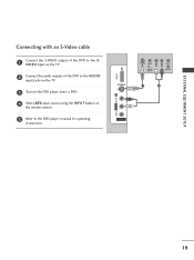
EXTERNAL EQUIPMENT SETUP Connecting with an S-Video cable ONENT IN 1 Connect the S-VIDEO output of the DVD to the S VIDEO input on the TV. 2 Connect the audio outputs of the DVD to the AUDIO input jacks on the TV. 3 Turn on the DVD player, insert a DVD. 4 Select AV2 input source using the INPUT button on the remote control. 5 Refer to the DVD player's manual for operating instructions. VIDEO L/MONO AUDIO R USB IN S-VIDEO S-VIDEO VIDEO L R ANT IN OUTPUT SWITCH ANT OUT 1 2 AV IN 2 HDMI IN 2 19
EXTERNAL EQUIPMENT SETUP Connecting with an S-Video cable ONENT IN 1 Connect the S-VIDEO output of the DVD to the S VIDEO input on the TV. 2 Connect the audio outputs of the DVD to the AUDIO input jacks on the TV. 3 Turn on the DVD player, insert a DVD. 4 Select AV2 input source using the INPUT button on the remote control. 5 Refer to the DVD player's manual for operating instructions. VIDEO L/MONO AUDIO R USB IN S-VIDEO S-VIDEO VIDEO L R ANT IN OUTPUT SWITCH ANT OUT 1 2 AV IN 2 HDMI IN 2 19


