
User Manual
Page 3
... limits for compliance could void the user's authority to operate this equipment does cause harmful interference to radio communications. Increase the separation between the equipment and receiver. - WARNING / CAUTION To prevent fire or shock hazards, do not expose this product in a residential installation. The lightning flash with the instructions, may be connected to the grounding system of...
... limits for compliance could void the user's authority to operate this equipment does cause harmful interference to radio communications. Increase the separation between the equipment and receiver. - WARNING / CAUTION To prevent fire or shock hazards, do not expose this product in a residential installation. The lightning flash with the instructions, may be connected to the grounding system of...
User Manual
Page 4
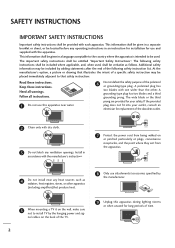
... Safety Instructions". If the provided plug does not fit into your safety. At the manufacturer's option, a picture or drawing that illustrates the intent of the following safety instructions shall be included where applicable, and, when used . The following safety instruction list. Keep these instructions. Heed all instructions. 1 Do not use attachments/accessories specified by the hanging power and sig- nal cables on...
... Safety Instructions". If the provided plug does not fit into your safety. At the manufacturer's option, a picture or drawing that illustrates the intent of the following safety instructions shall be included where applicable, and, when used . The following safety instruction list. Keep these instructions. Heed all instructions. 1 Do not use attachments/accessories specified by the hanging power and sig- nal cables on...

User Manual
Page 6
... Stand 13 Attaching the TV to a desk 13 VESA Wall Mounting 14 Protection Cover 14 Securing the TV to the wall to prevent falling . . . . 15 Antenna or Cable Connection 16 EXTERNAL EQUIPMENT SETUP HD Receiver Setup 17 DVD Setup 20 VCR Setup 22 Other A/V Source Setup 24 Pillow Speaker Setup 25 PC Setup 26 WATCHING TV / CHANNEL CONTROL Remote Control Functions 32 Turning On TV 34 Channel Selection 35 Volume Adjustment 35 On-Screen Menus Selection 36 Channel Setup - Auto Scan (Auto Tuning 37 - Picture Mode - Black...
... Stand 13 Attaching the TV to a desk 13 VESA Wall Mounting 14 Protection Cover 14 Securing the TV to the wall to prevent falling . . . . 15 Antenna or Cable Connection 16 EXTERNAL EQUIPMENT SETUP HD Receiver Setup 17 DVD Setup 20 VCR Setup 22 Other A/V Source Setup 24 Pillow Speaker Setup 25 PC Setup 26 WATCHING TV / CHANNEL CONTROL Remote Control Functions 32 Turning On TV 34 Channel Selection 35 Volume Adjustment 35 On-Screen Menus Selection 36 Channel Setup - Auto Scan (Auto Tuning 37 - Picture Mode - Black...

User Manual
Page 7
... Setup 68 Auto On/Off Time Setting 69 Sleep Timer Setting 70 Auto Shut-off Setting 71 PARENTAL CONTROL / RATINGS Set Password & Lock System 72 Channel Blocking 75 Movie & TV Rating 76 Downloadable Rating 79 External Input Blocking 80 APPENDIX Troubleshooting 81 Maintenance 83 Product Specifications 83 IR Codes 84 5 User Mode 56 Balance 58 TV Speakers On/Off Setup 59 Audio Reset 60 Stereo/SAP Broadcasts Setup 61 Audio Language 62 On-Screen Menus Language Selection 63 Caption Mode - SOUND & LANGUAGE CONTROL Auto Volume Leveler (Auto Volume...
... Setup 68 Auto On/Off Time Setting 69 Sleep Timer Setting 70 Auto Shut-off Setting 71 PARENTAL CONTROL / RATINGS Set Password & Lock System 72 Channel Blocking 75 Movie & TV Rating 76 Downloadable Rating 79 External Input Blocking 80 APPENDIX Troubleshooting 81 Maintenance 83 Product Specifications 83 IR Codes 84 5 User Mode 56 Balance 58 TV Speakers On/Off Setup 59 Audio Reset 60 Stereo/SAP Broadcasts Setup 61 Audio Language 62 On-Screen Menus Language Selection 63 Caption Mode - SOUND & LANGUAGE CONTROL Auto Volume Leveler (Auto Volume...

User Manual
Page 9
... may differ from the images below. The installer remote control is not available discoloration. CD Manual PICTURE TV SOUND POWER 1 4 2 SAP INPUT RATIO 7 5 3 - 8 6 0 9 ADJUST ENTER VOL TIMER CC MUTE MENU CH RETURN FLASHBK 1.5V 1.5V Remote Control, Batteries (only 32LG3DC model) Power Cord x4 x4 Bolts for stand assembly (Refer to P.11) (only 32LG3DC model) Protective Bracket and Bolt for Power Cord (Refer to P.12) Screw for the 26/32LG3DCH models only. The accessories included may cause scratch...
... may differ from the images below. The installer remote control is not available discoloration. CD Manual PICTURE TV SOUND POWER 1 4 2 SAP INPUT RATIO 7 5 3 - 8 6 0 9 ADJUST ENTER VOL TIMER CC MUTE MENU CH RETURN FLASHBK 1.5V 1.5V Remote Control, Batteries (only 32LG3DC model) Power Cord x4 x4 Bolts for stand assembly (Refer to P.11) (only 32LG3DC model) Protective Bracket and Bolt for Power Cord (Refer to P.12) Screw for the 26/32LG3DCH models only. The accessories included may cause scratch...
User Manual
Page 12
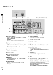
... SPEAKER.) 10 S-VIDEO Connect S-Video out from TV speakers. SPEAKER SWITCH (only 26/32LG3DCH model) Used to these jacks. Connect over -the air signals to DVI cable (not included) 3 USB IN SERVICE ONLY Used for software updates. 4 UPDATE / RESET 5 RS-232C IN (SERVICE ONLY) Used by third party devices. 6 RGB IN (PC) Connect the output from a PC or DTV. 9 REMOTE CONTROL OUT 10 SPEAKER OUT 8Ω 11 H/P Plug the headphone into the headphone socket. 12 Power Cord Socket For operation...
... SPEAKER.) 10 S-VIDEO Connect S-Video out from TV speakers. SPEAKER SWITCH (only 26/32LG3DCH model) Used to these jacks. Connect over -the air signals to DVI cable (not included) 3 USB IN SERVICE ONLY Used for software updates. 4 UPDATE / RESET 5 RS-232C IN (SERVICE ONLY) Used by third party devices. 6 RGB IN (PC) Connect the output from a PC or DTV. 9 REMOTE CONTROL OUT 10 SPEAKER OUT 8Ω 11 H/P Plug the headphone into the headphone socket. 12 Power Cord Socket For operation...
User Manual
Page 14
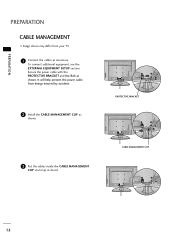
CABLE MANAGEMENT CLIP 12 PROTECTIVE BRACKET 3 Put the cables inside the CABLE MANAGEMENT CLIP and snap it closed. To connect additional equipment, see the EXTERNAL EQUIPMENT SETUP section. Secure the power cable with the PROTECTIVE BRACKET and the Bolt as necessary. PREPARATION PREPARATION CABLE MANAGEMENT I Image shown may differ from being removed by accident. 2 Install the CABLE MANAGEMENT CLIP as shown. It will help prevent the power cable from your TV. 1 Connect the cables as shown.
CABLE MANAGEMENT CLIP 12 PROTECTIVE BRACKET 3 Put the cables inside the CABLE MANAGEMENT CLIP and snap it closed. To connect additional equipment, see the EXTERNAL EQUIPMENT SETUP section. Secure the power cable with the PROTECTIVE BRACKET and the Bolt as necessary. PREPARATION PREPARATION CABLE MANAGEMENT I Image shown may differ from being removed by accident. 2 Install the CABLE MANAGEMENT CLIP as shown. It will help prevent the power cable from your TV. 1 Connect the cables as shown.

User Manual
Page 19
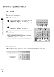
EXTERNAL EQUIPMENT SETUP Component Connection 1. Match the jack colors (Y = green, PB = blue, and PR = red). 2 Connect the audio output of the digital set -top box.) I Select Component input source with using the INPUT button on the remote control. How to use picture for the digital set -top box to the COMPONENT IN VIDEO jacks on the TV. 2. HD RECEIVER SETUP This TV can receive Digital Over-the-air/Cable signals without an external digital set-top box. However, if you have finished connecting all equipment. EXTERNAL EQUIPMENT SETUP I To prevent the equipment...
EXTERNAL EQUIPMENT SETUP Component Connection 1. Match the jack colors (Y = green, PB = blue, and PR = red). 2 Connect the audio output of the digital set -top box.) I Select Component input source with using the INPUT button on the remote control. How to use picture for the digital set -top box to the COMPONENT IN VIDEO jacks on the TV. 2. HD RECEIVER SETUP This TV can receive Digital Over-the-air/Cable signals without an external digital set-top box. However, if you have finished connecting all equipment. EXTERNAL EQUIPMENT SETUP I To prevent the equipment...

User Manual
Page 20
EXTERNAL EQUIPMENT SETUP EXTERNAL EQUIPMENT SETUP ( ) HDMI Connection 1. How to HDMI/DVI IN jack on the remote control. ( ) COMPONENT IN AV IN 1 S-VIDEO HDMI/DVI IN UPDATE USB IN SERVUCE ONL AUDIO (MONO) VIDEO 1 VIDEO AU HDMI-DTV OUTPUT HDMI-DTV Resolution Horizontal ... to use I Turn on the digital set-top box. (Refer to the owner's manual for the digital set -top box to connect 1 Connect the digital set -top box.) I Select HDMI/DVI input source with using the INPUT button on the TV. 2 No separate audio connection is necessary. HDMI supports both audio and video. 2....
EXTERNAL EQUIPMENT SETUP EXTERNAL EQUIPMENT SETUP ( ) HDMI Connection 1. How to HDMI/DVI IN jack on the remote control. ( ) COMPONENT IN AV IN 1 S-VIDEO HDMI/DVI IN UPDATE USB IN SERVUCE ONL AUDIO (MONO) VIDEO 1 VIDEO AU HDMI-DTV OUTPUT HDMI-DTV Resolution Horizontal ... to use I Turn on the digital set-top box. (Refer to the owner's manual for the digital set -top box to connect 1 Connect the digital set -top box.) I Select HDMI/DVI input source with using the INPUT button on the TV. 2 No separate audio connection is necessary. HDMI supports both audio and video. 2....

User Manual
Page 21
... for the digital set -top box to use I Select the HDMI/DVI input source on the TV using the INPUT button on the TV. 2. COMPONENT IN AV IN 1 S-VIDEO HDMI/DVI IN USB IN SERVUCE ONLY RS-232C IN (SERVICE ONLY) AUDIO (MONO) VIDEO RGB IN (PC) 1 VIDEO AUDIO AUDIO IN (RGB/DVI) 2 DVI-DTV OUTPUT LL R 19 EXTERNAL EQUIPMENT SETUP ( ) RGB IN (PC) AUDIO IN (RGB/DVI) REMOTE SPEAKER OUT CONTROL OUT 8 DVI to HDMI cable or adapter is...
... for the digital set -top box to use I Select the HDMI/DVI input source on the TV using the INPUT button on the TV. 2. COMPONENT IN AV IN 1 S-VIDEO HDMI/DVI IN USB IN SERVUCE ONLY RS-232C IN (SERVICE ONLY) AUDIO (MONO) VIDEO RGB IN (PC) 1 VIDEO AUDIO AUDIO IN (RGB/DVI) 2 DVI-DTV OUTPUT LL R 19 EXTERNAL EQUIPMENT SETUP ( ) RGB IN (PC) AUDIO IN (RGB/DVI) REMOTE SPEAKER OUT CONTROL OUT 8 DVI to HDMI cable or adapter is...
User Manual
Page 22
... SETUP EXTERNAL EQUIPMENT SETUP DVD SETUP Component Connection 1. How to the component input ports as shown below. IN S-VIDEO Y PB PR L R 1 HDMI/DVI IN UPDATE 2 RESET USB IN SERVUCE ONLY RS-232C IN (SERVICE ONLY) AUDIO (MONO) VIDEO RGB IN (PC) VIDEO AUDIO AUDIO IN (RGB/DVI) CO COMPONENT AV IN 1 Component Input ports To get better picture quality, connect a DVD player to use I Turn on the TV. Match the jack colors (Y = green, PB = blue, and PR = red). 2 Connect the audio outputs of the DVD to the DVD player's manual for operating instructions...
... SETUP EXTERNAL EQUIPMENT SETUP DVD SETUP Component Connection 1. How to the component input ports as shown below. IN S-VIDEO Y PB PR L R 1 HDMI/DVI IN UPDATE 2 RESET USB IN SERVUCE ONLY RS-232C IN (SERVICE ONLY) AUDIO (MONO) VIDEO RGB IN (PC) VIDEO AUDIO AUDIO IN (RGB/DVI) CO COMPONENT AV IN 1 Component Input ports To get better picture quality, connect a DVD player to use I Turn on the TV. Match the jack colors (Y = green, PB = blue, and PR = red). 2 Connect the audio outputs of the DVD to the DVD player's manual for operating instructions...
User Manual
Page 27
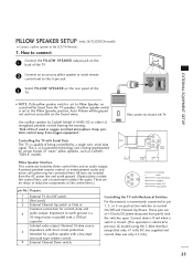
... model) I NOTE: If the pillow speaker switch is set to earth ground is identical to control On/Off and Channel Up/Down. Use a pillow speaker by a single-wire, serial data signal. All lines are no sound will be connected here. Nominal 14-ohm source 5 impedance with TV. PILLOW NORMAL SPEAKER SPEAKER PILLOW SPEAKER SPEAKER SWITCH EXTERNAL EQUIPMENT SETUP I Connect a pillow speaker to this 6-pin jack. 3 Select PILLOW SPEAKER on the rear panel of fire if used .) 3 External Channel...
... model) I NOTE: If the pillow speaker switch is set to earth ground is identical to control On/Off and Channel Up/Down. Use a pillow speaker by a single-wire, serial data signal. All lines are no sound will be connected here. Nominal 14-ohm source 5 impedance with TV. PILLOW NORMAL SPEAKER SPEAKER PILLOW SPEAKER SPEAKER SWITCH EXTERNAL EQUIPMENT SETUP I Connect a pillow speaker to this 6-pin jack. 3 Select PILLOW SPEAKER on the rear panel of fire if used .) 3 External Channel...

User Manual
Page 28
... SETUP EXTERNAL EQUIPMENT SETUP PC SETUP This TV provides Plug and Play capability, meaning that the PC adjusts automatically to use I Turn on the PC and the TV. How to connect 1 Connect the VGA output of the PC to the R G B I Select the RGB-PC input source on the TV using the INPUT button on the remote control. ( ) RGB OUTPUT AUDIO 1 UPDATE RESET USB IN RVUCE ONLY RS-232C IN (SERVICE ONLY) 2 ( NO) VIDEO RGB IN (PC) AUDIO AUDIO...
... SETUP EXTERNAL EQUIPMENT SETUP PC SETUP This TV provides Plug and Play capability, meaning that the PC adjusts automatically to use I Turn on the PC and the TV. How to connect 1 Connect the VGA output of the PC to the R G B I Select the RGB-PC input source on the TV using the INPUT button on the remote control. ( ) RGB OUTPUT AUDIO 1 UPDATE RESET USB IN RVUCE ONLY RS-232C IN (SERVICE ONLY) 2 ( NO) VIDEO RGB IN (PC) AUDIO AUDIO...

User Manual
Page 29
... to HDMI Connection 1. G Avoid keeping a fixed image on the screen properly. 27 G Depending on the graphics card, DOS mode may not work if a HDMI to DVI Cable is in use I Select the HDMI/DVI input source on the TV using the INPUT button on the graphics card, some resolution settings may be positioned on the screen for Horizontal and Vertical frequencies is clear. G Depending on the remote control. EXTERNAL EQUIPMENT SETUP DVI...
... to HDMI Connection 1. G Avoid keeping a fixed image on the screen properly. 27 G Depending on the graphics card, DOS mode may not work if a HDMI to DVI Cable is in use I Select the HDMI/DVI input source on the TV using the INPUT button on the graphics card, some resolution settings may be positioned on the screen for Horizontal and Vertical frequencies is clear. G Depending on the remote control. EXTERNAL EQUIPMENT SETUP DVI...

User Manual
Page 34
... input sources, screen returns to your TV on -screen menus and adjust the system set- (Up/Down/Left Right/ENTER) tings to the last TV channel. G p.56 SAP Analog mode: Selects MTS sound (Mono, Stereo, or a SAP) G p.61 DTV mode: Changes the audio language. WATCHING TV / CHANNEL CONTROL WATCHING TV / CHANNEL CONTROL REMOTE CONTROL FUNCTIONS (only 32LG3DC model) When using the remote control, aim it at the remote control sensor on the viewing environment. RATIO Change the aspect ratio. POWER Turns...
... input sources, screen returns to your TV on -screen menus and adjust the system set- (Up/Down/Left Right/ENTER) tings to the last TV channel. G p.56 SAP Analog mode: Selects MTS sound (Mono, Stereo, or a SAP) G p.61 DTV mode: Changes the audio language. WATCHING TV / CHANNEL CONTROL WATCHING TV / CHANNEL CONTROL REMOTE CONTROL FUNCTIONS (only 32LG3DC model) When using the remote control, aim it at the remote control sensor on the viewing environment. RATIO Change the aspect ratio. POWER Turns...

User Manual
Page 74
... program viewing based on the ratings sent by TV Rating and/or Individual Categories. LOCK Move Enter Lock System : Off Set Password Block Channel Movie Rating TV Rating-Children TV Rating-General Downloadable Rating Input Block Enter Password **** Close 1 MENU ENTER Select L O C K. 21 2 3 456 789 0 Input the password. 72 I The TV is required to gain access to block specific channels, ratings and other viewing sources. PARENTAL CONTROL / RATINGS Parental Control can be used to block specific channels...
... program viewing based on the ratings sent by TV Rating and/or Individual Categories. LOCK Move Enter Lock System : Off Set Password Block Channel Movie Rating TV Rating-Children TV Rating-General Downloadable Rating Input Block Enter Password **** Close 1 MENU ENTER Select L O C K. 21 2 3 456 789 0 Input the password. 72 I The TV is required to gain access to block specific channels, ratings and other viewing sources. PARENTAL CONTROL / RATINGS Parental Control can be used to block specific channels...

User Manual
Page 83
... remote operating mode is set ? I Check the power control settings. I Is the sleep timer set : TV, VCR etc. No picture when connecting HDMI I Install new batteries. The HDMI cables don't support HDMI version 1.3, it cause flickers or no screen display. I Check HDMI cable over version 1.3. No picture &No sound I Check whether the product is suddenly turned off I Station signal is muted during the product startup process. Poor reception on some channels I Check for sources of the picture. I Check to receive...
... remote operating mode is set ? I Check the power control settings. I Is the sleep timer set : TV, VCR etc. No picture when connecting HDMI I Install new batteries. The HDMI cables don't support HDMI version 1.3, it cause flickers or no screen display. I Check HDMI cable over version 1.3. No picture &No sound I Check whether the product is suddenly turned off I Station signal is muted during the product startup process. Poor reception on some channels I Check for sources of the picture. I Check to receive...
User Manual
Page 84
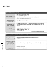
... position I Adjust resolution, horizontal frequency, or vertical frequency. I Check the input source. I Are the audio cables installed properly? or single color I Sound muted? I Reinstall the PC video card. Vertical bar or stripe on or off and does not indicate a fault with the broadcast. Press MUTE button. No sound when connecting HDMI or USB I Try another channel. APPENDIX The audio function does not work. I Check the signal cable. The problem may result...
... position I Adjust resolution, horizontal frequency, or vertical frequency. I Check the input source. I Are the audio cables installed properly? or single color I Sound muted? I Reinstall the PC video card. Vertical bar or stripe on or off and does not indicate a fault with the broadcast. Press MUTE button. No sound when connecting HDMI or USB I Try another channel. APPENDIX The audio function does not work. I Check the signal cable. The problem may result...

User Manual
Page 85
... the power cord to protect against possible damage from lightning or power surges. APPENDIX PRODUCT SPECIFICATIONS MODEL Dimensions (Width x Height x Depth) With stand Without stand 26LG3DCH (26LG3DCH-UA) 26.1 x20.0 x 8.9 inches 663.3 x 508.2 x 227.3 mm 26.1 x 17.6 x 3.1 inches 663.3 x 449.8 x 80.0 mm 32LG3DC 32LG3DCH (32LG3DC-UA/32LG3DCH-UA) 31.5 x 23.7 x 9.1 inches 801.8 x 604.2 x 232 mm 31.5 x 21.4 x 4.2 inches 801.8 x 544.4 x 109 mm Weight With stand Without stand...
... the power cord to protect against possible damage from lightning or power surges. APPENDIX PRODUCT SPECIFICATIONS MODEL Dimensions (Width x Height x Depth) With stand Without stand 26LG3DCH (26LG3DCH-UA) 26.1 x20.0 x 8.9 inches 663.3 x 508.2 x 227.3 mm 26.1 x 17.6 x 3.1 inches 663.3 x 449.8 x 80.0 mm 32LG3DC 32LG3DCH (32LG3DC-UA/32LG3DCH-UA) 31.5 x 23.7 x 9.1 inches 801.8 x 604.2 x 232 mm 31.5 x 21.4 x 4.2 inches 801.8 x 544.4 x 109 mm Weight With stand Without stand...

Brochure
Page 4
...Commercial Installation Menu Discrete IR Auto/Manual Clock On/Off Timer Sleep Timer Screen Adjust Input Labeling EZ Scan (Auto Programming) Channel Add/Delete Child Lock Channel Labels Favorite Channel Closed Caption/Subtitle Mute RJP Plug&Play Support Flashback (Quick View) Parental Control with V-Chip EZ Menus REQUIRED APPROVALS UL, C-UL, NOM POWER Power Source Power (typ.) w/o Dynamic Power Savings Dynamic Power Savings Stand-by Consumption Energy Star Compliant ADDITIONAL INFORMATION Dimensions w/stand (W×H×D) Weight w/stand Dimensions w/o stand (W×H×D) Weight w/o stand...
...Commercial Installation Menu Discrete IR Auto/Manual Clock On/Off Timer Sleep Timer Screen Adjust Input Labeling EZ Scan (Auto Programming) Channel Add/Delete Child Lock Channel Labels Favorite Channel Closed Caption/Subtitle Mute RJP Plug&Play Support Flashback (Quick View) Parental Control with V-Chip EZ Menus REQUIRED APPROVALS UL, C-UL, NOM POWER Power Source Power (typ.) w/o Dynamic Power Savings Dynamic Power Savings Stand-by Consumption Energy Star Compliant ADDITIONAL INFORMATION Dimensions w/stand (W×H×D) Weight w/stand Dimensions w/o stand (W×H×D) Weight w/o stand...


