Owners Manual
Page 4
... guide mode 65 Button function in 8 days guide mode 65 Button function in date change mode 65 Button function in extended description box 66 Button function in record/remind setting mode 66 Button function in timer list mode 66 PICTURE CONTROL Picture Size (Aspect Ratio) Control 67 Preset Picture Settings - Screen Setup for Wire Arrangement 15 Desktop Pedestal Installation 19 Wall Mount: Horizontal installation 20 Antenna Connection 21 EXTERNAL EQUIPMENT SETUP HD Receiver Setup 22 DVD Setup 25 Insertion of CI module 28 VCR Setup 29 Digital Audio Out Setup 31 Other A/V Source...
... guide mode 65 Button function in 8 days guide mode 65 Button function in date change mode 65 Button function in extended description box 66 Button function in record/remind setting mode 66 Button function in timer list mode 66 PICTURE CONTROL Picture Size (Aspect Ratio) Control 67 Preset Picture Settings - Screen Setup for Wire Arrangement 15 Desktop Pedestal Installation 19 Wall Mount: Horizontal installation 20 Antenna Connection 21 EXTERNAL EQUIPMENT SETUP HD Receiver Setup 22 DVD Setup 25 Insertion of CI module 28 VCR Setup 29 Digital Audio Out Setup 31 Other A/V Source...
Owners Manual
Page 9
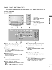
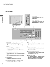
... from an S-VIDEO device. Note: In standby mode, these ports do not work. 7 8 6 RS-232C IN (CONTROL & SERVICE) PORT Connect to the RS-232C port on a PC. 7 Component Input Connect a component video/audio device to these jacks. 8 Euro Scart Socket (AV1/AV2) Connect scart socket input or output from an external device to operate the TV on DC power. 7 Never attempt to these jacks. 9 Power Cord Socket This TV operates on the Specifications page. Audio/Video Input Connect audio/video output from an external device to...
... from an S-VIDEO device. Note: In standby mode, these ports do not work. 7 8 6 RS-232C IN (CONTROL & SERVICE) PORT Connect to the RS-232C port on a PC. 7 Component Input Connect a component video/audio device to these jacks. 8 Euro Scart Socket (AV1/AV2) Connect scart socket input or output from an external device to operate the TV on DC power. 7 Never attempt to these jacks. 9 Power Cord Socket This TV operates on the Specifications page. Audio/Video Input Connect audio/video output from an external device to...
Owners Manual
Page 11
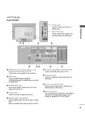
... LCD TV Models Except 26/32LB7* 91 VIDEO L/MONO AUDIO R VIDEO L/MONO AUDIO R S-VIDEO S-VIDEO AV IN 3 AV IN 3 2 VIDEO L/MONO AUDIO R S-Video Input S-VIDEO Connect S-Video out from various types of equipment. Note: In standby mode, these ports do not work. 6 RS-232C IN (CONTROL & SERVICE) PORT Connect to the RS-232C port on a PC. 7 Component Input Connect a component video/audio device to these jacks. 8 Euro Scart Socket (AV1/AV2) Connect scart socket input or output from an external device to these jacks. 9 Power Cord Socket This TV operates on...
... LCD TV Models Except 26/32LB7* 91 VIDEO L/MONO AUDIO R VIDEO L/MONO AUDIO R S-VIDEO S-VIDEO AV IN 3 AV IN 3 2 VIDEO L/MONO AUDIO R S-Video Input S-VIDEO Connect S-Video out from various types of equipment. Note: In standby mode, these ports do not work. 6 RS-232C IN (CONTROL & SERVICE) PORT Connect to the RS-232C port on a PC. 7 Component Input Connect a component video/audio device to these jacks. 8 Euro Scart Socket (AV1/AV2) Connect scart socket input or output from an external device to these jacks. 9 Power Cord Socket This TV operates on...
Owners Manual
Page 12
... 26/32LB7* VIDEO L/MONO AUDIO R VIDEO L/MONO AUDIO R USB IN DIGITAL AUDIO OUT VIDEO L/MONO AUDIO R PREPARATION 91 S-VIDEO AV IN 3 AV IN 2 2 S-Video Input S-VIDEO Connect S-Video out from an external device to these jacks. 9 Power Cord Socket This TV operates on an AC power. Note: In standby mode, these ports do not work. 4 Antenna Input Connect over-the-air signals to this jack. 7 RGB/DVI Audio Input Connect the monitor output from a PC to HDMI IN. The voltage is not available in all countries.) VIDEO AUDIO COMPONENT...
... 26/32LB7* VIDEO L/MONO AUDIO R VIDEO L/MONO AUDIO R USB IN DIGITAL AUDIO OUT VIDEO L/MONO AUDIO R PREPARATION 91 S-VIDEO AV IN 3 AV IN 2 2 S-Video Input S-VIDEO Connect S-Video out from an external device to these jacks. 9 Power Cord Socket This TV operates on an AC power. Note: In standby mode, these ports do not work. 4 Antenna Input Connect over-the-air signals to this jack. 7 RGB/DVI Audio Input Connect the monitor output from a PC to HDMI IN. The voltage is not available in all countries.) VIDEO AUDIO COMPONENT...
Owners Manual
Page 24
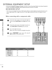
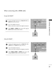
When connecting with a component cable 1 Connect the video outputs (Y, PB, PR) of the digital set top box to the COMPONENT IN VIDEO jacks on the set. 2 Connect the audio output of EXTERNAL EQUIPMENT SETUP mainly use pictures for the digital set-top box.) 1 2 4 Select COMPONENT input source with using the INPUT button on the digital set-top box. (Refer to the owner's manual for the LCD TV models. I This part of the digital set-top box to the COMPONENT IN AUDIO jacks on the set. 3 Turn on the remoCtAPeRCDcMoSCnLItAOrTol. EJECT HDMI/DVI IN 1 HDMI IN 2 RGB IN...
When connecting with a component cable 1 Connect the video outputs (Y, PB, PR) of the digital set top box to the COMPONENT IN VIDEO jacks on the set. 2 Connect the audio output of EXTERNAL EQUIPMENT SETUP mainly use pictures for the digital set-top box.) 1 2 4 Select COMPONENT input source with using the INPUT button on the digital set-top box. (Refer to the owner's manual for the LCD TV models. I This part of the digital set-top box to the COMPONENT IN AUDIO jacks on the set. 3 Turn on the remoCtAPeRCDcMoSCnLItAOrTol. EJECT HDMI/DVI IN 1 HDMI IN 2 RGB IN...
Owners Manual
Page 25
... the owner's manual for the digital set-top box.) 3 Select HDMI1, HDMI2 or HDMI3 input source with using the INPUT button on the remote control. OPTIC RS-232C IN (CONTROL & SERVICE) RGB(PC) AUD (RG 2 Turn on the set. RS-232C IN 1(CONTROL & SERVICE) AV 1 AV EXTERNAL EQUIPMENT SETUP Only 26/32LB7* PCMCIA CARD SLOT EJECT HDMI/DVI IN 1 HDMI IN 2 HDMI IN 3 1 Connect the digital set-top box to HDMI/DVI IN 1, HDMI IN 2 or HDMI IN 3 jack on the digital set-top box...
... the owner's manual for the digital set-top box.) 3 Select HDMI1, HDMI2 or HDMI3 input source with using the INPUT button on the remote control. OPTIC RS-232C IN (CONTROL & SERVICE) RGB(PC) AUD (RG 2 Turn on the set. RS-232C IN 1(CONTROL & SERVICE) AV 1 AV EXTERNAL EQUIPMENT SETUP Only 26/32LB7* PCMCIA CARD SLOT EJECT HDMI/DVI IN 1 HDMI IN 2 HDMI IN 3 1 Connect the digital set-top box to HDMI/DVI IN 1, HDMI IN 2 or HDMI IN 3 jack on the digital set-top box...

Owners Manual
Page 26
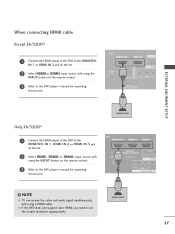
... set. Turn on the digital set-top box. (Refer to the owner's manual for the digital set-top box.) AV 1 AV 2 4 Select HDMI1 input source with using the INPUT button on the set. VIDEO AUDIO RS-232C IN Only 26/32LB7* IN 2 HDMI IN 3 N ERVICE) VIDEO AV 1 AV 2 PCMCIA CARD SLOT EJECT HDMI/DVI IN 1 HDMI IN 2 HDMI IN 3 1 2 AUDIO 3 Connect the digital set-top box to HDMI/DVI IN 1 jack on the remote control. 24 Connect the audio output of the digital set-top box to OPTICAL the AUDIO...
... set. Turn on the digital set-top box. (Refer to the owner's manual for the digital set-top box.) AV 1 AV 2 4 Select HDMI1 input source with using the INPUT button on the set. VIDEO AUDIO RS-232C IN Only 26/32LB7* IN 2 HDMI IN 3 N ERVICE) VIDEO AV 1 AV 2 PCMCIA CARD SLOT EJECT HDMI/DVI IN 1 HDMI IN 2 HDMI IN 3 1 2 AUDIO 3 Connect the digital set-top box to HDMI/DVI IN 1 jack on the remote control. 24 Connect the audio output of the digital set-top box to OPTICAL the AUDIO...
Owners Manual
Page 29
.... 1 VIDEO AUDIO COMPONENT IN ! DIGITAL AUDIO OUT COMP VIDEO AUDIO 2 Select HDMI1or HDMI2 input source with using a HDMI cable. AV 1 AV 2 VIDEO L/MONO AUDIO R AUDIO AV IN 3 When connecting HDMI cable Except 26/32LB7* MI IN 2 AV 1 AV 2 PCMCIA EJECT CARD SLOT HDMI/DVI IN 1 HDMI IN 2 R A RGB(P 1 Connect the HDMI output of the DVD to the DVD player's manual for operating instructions. 1 RS-232C IN (CONTROL & SERVICE) EXTERNAL EQUIPMENT SETUP Only 26/32LB7* PCMCIA EJECT 1 Connect the HDMI output of the DVD to set . NOTE G TV can receive the video and audio signal...
.... 1 VIDEO AUDIO COMPONENT IN ! DIGITAL AUDIO OUT COMP VIDEO AUDIO 2 Select HDMI1or HDMI2 input source with using a HDMI cable. AV 1 AV 2 VIDEO L/MONO AUDIO R AUDIO AV IN 3 When connecting HDMI cable Except 26/32LB7* MI IN 2 AV 1 AV 2 PCMCIA EJECT CARD SLOT HDMI/DVI IN 1 HDMI IN 2 R A RGB(P 1 Connect the HDMI output of the DVD to the DVD player's manual for operating instructions. 1 RS-232C IN (CONTROL & SERVICE) EXTERNAL EQUIPMENT SETUP Only 26/32LB7* PCMCIA EJECT 1 Connect the HDMI output of the DVD to set . NOTE G TV can receive the video and audio signal...

Owners Manual
Page 35
... 1 AV 2 COMPONENT IN AV 2 DIGITAL AUDIO OUT OPTICAL VIDEO AUDIO ANTENNA 2 Connect the PC audio output to 1024x768, 60Hz. 33 RVISD-E2O32C IN AUDIO (CONTROL & SER1VICE) 2 3 Turn on the PC and the set RS-232C IN 4 Select HDMI1 input source with using the INPUT button on the remote control. To get the best picture quality, adjust the output resolution of the PC to the H D M I / D V I HDMI/DVI IN 1 HDMI IN 2 IN 1 jack on the set. PC SETUP This TV provides Plug and Play capability...
... 1 AV 2 COMPONENT IN AV 2 DIGITAL AUDIO OUT OPTICAL VIDEO AUDIO ANTENNA 2 Connect the PC audio output to 1024x768, 60Hz. 33 RVISD-E2O32C IN AUDIO (CONTROL & SER1VICE) 2 3 Turn on the PC and the set RS-232C IN 4 Select HDMI1 input source with using the INPUT button on the remote control. To get the best picture quality, adjust the output resolution of the PC to the H D M I / D V I HDMI/DVI IN 1 HDMI IN 2 IN 1 jack on the set. PC SETUP This TV provides Plug and Play capability...

Owners Manual
Page 36
... does not output analog and digital RGB simultaneously, connect only one of the set 's screen for Plug and Play functionally. EXTERNAL EQUIPMENT SETUP ! use a HDMI to the Audio input on the menu until the picture is preset for RGB (Analog RGB), HDMI (Digital RGB) mode. Change the PC mode into another resolution or change the refresh rate into another rate or adjust the brightness and contrast on the set . G In Plasma TV models, we recommend using this set . (Audio cables are separate...
... does not output analog and digital RGB simultaneously, connect only one of the set 's screen for Plug and Play functionally. EXTERNAL EQUIPMENT SETUP ! use a HDMI to the Audio input on the menu until the picture is preset for RGB (Analog RGB), HDMI (Digital RGB) mode. Change the PC mode into another resolution or change the refresh rate into another rate or adjust the brightness and contrast on the set . G In Plasma TV models, we recommend using this set . (Audio cables are separate...

Owners Manual
Page 43
... install the batteries matching correct polarity (+with +,-with new ones. VCR/DVD Controls some video cassette recorders or DVD players control buttons when you toggle this button, the Simplink menu appears at the screen. (G p.62) 1 TELETEXT These buttons are used batteries with -). BUTTONS For further details, see the 'Teletext' section. I /II 1 BACK MENU INFO i EXIT GUIDE OK FAV VOL PR MUTE 1 2 3 4 5 6 7 8 9 LIST 0 Q.VIEW 1 UPDATE INDEX TIME ? SUBTITLE Recalls your preference. INPUT D/A POWER MODE TV TV/RADIO INPUT...
... install the batteries matching correct polarity (+with +,-with new ones. VCR/DVD Controls some video cassette recorders or DVD players control buttons when you toggle this button, the Simplink menu appears at the screen. (G p.62) 1 TELETEXT These buttons are used batteries with -). BUTTONS For further details, see the 'Teletext' section. I /II 1 BACK MENU INFO i EXIT GUIDE OK FAV VOL PR MUTE 1 2 3 4 5 6 7 8 9 LIST 0 Q.VIEW 1 UPDATE INDEX TIME ? SUBTITLE Recalls your preference. INPUT D/A POWER MODE TV TV/RADIO INPUT...
Owners Manual
Page 44
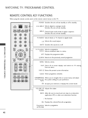
... any menu. MENU Selects a menu. RATIO SLEEP SUBTITLE UPDATE INDEX TIME HOLD REVEAL ? OK Accepts your preference. Q.VIEW Returns to move back one step in digital mode. EXIT Clears all on from standby. POWER TV INPUT D/A TV/RADIO TEXT I /II Selects the sound output. INPUT External input mode rotate in a menu. I /II MUTE 1 4 7 LIST MENU 2 3 5 6 8 9 0 Q.VIEW EXIT OK INFO i GUIDE BACK VOL * PR FAV POWER Switches the set on -screen displays and returns to navigate the on the TV. button Selects numbered items...
... any menu. MENU Selects a menu. RATIO SLEEP SUBTITLE UPDATE INDEX TIME HOLD REVEAL ? OK Accepts your preference. Q.VIEW Returns to move back one step in digital mode. EXIT Clears all on from standby. POWER TV INPUT D/A TV/RADIO TEXT I /II Selects the sound output. INPUT External input mode rotate in a menu. I /II MUTE 1 4 7 LIST MENU 2 3 5 6 8 9 0 Q.VIEW EXIT OK INFO i GUIDE BACK VOL * PR FAV POWER Switches the set on -screen displays and returns to navigate the on the TV. button Selects numbered items...
Owners Manual
Page 45
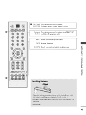
... matching correct polarity (+with +,-with new ones. Don't mix old or used batteries with -). WATCHING TV / PROGRAMME CONTROL POWER TV INPUT D/A TV/RADIO TEXT I/II MUTE 1 1 2 3 4 5 6 7 8 9 LIST 0 Q.VIEW MENU EXIT OK INFO i GUIDE BACK VOL * PR FAV RATIO SLEEP SUBTITLE UPDATE 1 INDEX TIME HOLD REVEAL ? 1 TELETEXT These buttons are used for teletext. BUTTONS For further details, see the 'Teletext' section. SUBTITLE Recalls your desired picture format. I Install two 1.5V AAA batteries.
... matching correct polarity (+with +,-with new ones. Don't mix old or used batteries with -). WATCHING TV / PROGRAMME CONTROL POWER TV INPUT D/A TV/RADIO TEXT I/II MUTE 1 1 2 3 4 5 6 7 8 9 LIST 0 Q.VIEW MENU EXIT OK INFO i GUIDE BACK VOL * PR FAV RATIO SLEEP SUBTITLE UPDATE 1 INDEX TIME HOLD REVEAL ? 1 TELETEXT These buttons are used for teletext. BUTTONS For further details, see the 'Teletext' section. SUBTITLE Recalls your desired picture format. I Install two 1.5V AAA batteries.
Owners Manual
Page 48
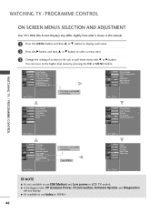
... 0 TV Speaker TIMEO Digital Audio Out OPTIONO SCREENO WATCHING TV / PROGRAMME CONTROL 46 Move MENU Prev. Move MENU Prev. Move MENU Prev. ! G It's available to use Index in 50PB6*. SETUPO Picture Mode PICTUREO Colour Temperature AUDIOO Advanced TIMEO Picture Reset OPTIONO Demo SCREENO Move MENU Prev. NOTE G It's not available to use ISM Method and Low power in LCD TV models. SETUPO Auto Tuning PICTUREO Manual Tuning AUDIOO Programme Edit 5V Antenna Power TIMEO Software Update OPTIONO...
... 0 TV Speaker TIMEO Digital Audio Out OPTIONO SCREENO WATCHING TV / PROGRAMME CONTROL 46 Move MENU Prev. Move MENU Prev. Move MENU Prev. ! G It's available to use Index in 50PB6*. SETUPO Picture Mode PICTUREO Colour Temperature AUDIOO Advanced TIMEO Picture Reset OPTIONO Demo SCREENO Move MENU Prev. NOTE G It's not available to use ISM Method and Low power in LCD TV models. SETUPO Auto Tuning PICTUREO Manual Tuning AUDIOO Programme Edit 5V Antenna Power TIMEO Software Update OPTIONO...
Owners Manual
Page 55
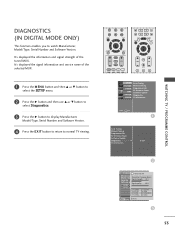
.... 1 Press the M E N U button and then D or E button to select the SETUP menu. 2 Press the G button and then use D or E button to select Diagnostics. 3 Press the G button to display Manufacturer, Model/Type, Serial Number and Software Version. 4 Press the EXIT button to return to watch Manufacturer, Model/Type, Serial Number and Software Version. It's displayed the signal information and service name of the tuned MUX. DIAGNOSTICS (IN DIGITAL MODE ONLY) This function enables you to normal TV viewing.
.... 1 Press the M E N U button and then D or E button to select the SETUP menu. 2 Press the G button and then use D or E button to select Diagnostics. 3 Press the G button to display Manufacturer, Model/Type, Serial Number and Software Version. 4 Press the EXIT button to return to watch Manufacturer, Model/Type, Serial Number and Software Version. It's displayed the signal information and service name of the tuned MUX. DIAGNOSTICS (IN DIGITAL MODE ONLY) This function enables you to normal TV viewing.
Owners Manual
Page 56
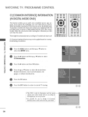
... CONTROL WATCHING TV /PROGRAMME CONTROL CI [COMMON INTERFACE] INFORMATION (IN DIGITAL MODE ONLY) This function enables you to CI module and smart card. Do not often insert or remove a CAM module from the set turned on country broadcasting circumstance. 7 LIST MENU 8 9 0 Q.VIEW EXIT OK INFO i GUIDE BACK VOL * PR FAV RATIO SLEEP SUBTITLE UPDATE BACK MENU INFO i EXIT GUIDE OK FAV VOL PR MUTE 1 2 3 1 Press the MENU button...
... CONTROL WATCHING TV /PROGRAMME CONTROL CI [COMMON INTERFACE] INFORMATION (IN DIGITAL MODE ONLY) This function enables you to CI module and smart card. Do not often insert or remove a CAM module from the set turned on country broadcasting circumstance. 7 LIST MENU 8 9 0 Q.VIEW EXIT OK INFO i GUIDE BACK VOL * PR FAV RATIO SLEEP SUBTITLE UPDATE BACK MENU INFO i EXIT GUIDE OK FAV VOL PR MUTE 1 2 3 1 Press the MENU button...
Owners Manual
Page 80
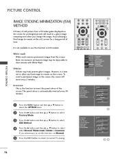
... Lock System Parental Control Input Label SIMPLINK Factory Mode Set ID 1 Factory Reset OK ISM Method G Normal Low Power Off 2 Language Country Lock System Parental Control Input Label SIMPLINK Factory Mode Set ID 1 Factory Reset OK ISM Method F G Normal Low Power Off 34 78 If you change the image. PICTURE CONTROL PICTURE CONTROL IMAGE STICKING MINIMIZATION (ISM) METHOD A frozen of still picture from the screen. Avoid allowing a fixed image to remain on the screen, the screen will result in LCD models. The panel...
... Lock System Parental Control Input Label SIMPLINK Factory Mode Set ID 1 Factory Reset OK ISM Method G Normal Low Power Off 2 Language Country Lock System Parental Control Input Label SIMPLINK Factory Mode Set ID 1 Factory Reset OK ISM Method F G Normal Low Power Off 34 78 If you change the image. PICTURE CONTROL PICTURE CONTROL IMAGE STICKING MINIMIZATION (ISM) METHOD A frozen of still picture from the screen. Avoid allowing a fixed image to remain on the screen, the screen will result in LCD models. The panel...
Owners Manual
Page 81
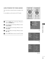
PICTURE CONTROL LOW-POWER PICTURE MODE This is the function to normal TV viewing. 7 LIST MENU 8 9 0 Q.VIEW EXIT OK INFO i GUIDE BACK VOL * PR FAV RATIO SLEEP SUBTITLE UPDATE BACK MENU INFO i EXIT GUIDE OK FAV VOL PR MUTE 1 2 3 SETUPO Language PICTUREO Country AUDIOO Lock System Parental Control TIMEO Input Label OPTIONO SIMPLINK SCREENO Factory Mode Move MENU Prev. 1 Language Country Lock System Parental Control Input Label SIMPLINK Factory Mode Set ID 1 Factory Reset OK ISM Method G Normal Low Power Off 2 Language Country...
PICTURE CONTROL LOW-POWER PICTURE MODE This is the function to normal TV viewing. 7 LIST MENU 8 9 0 Q.VIEW EXIT OK INFO i GUIDE BACK VOL * PR FAV RATIO SLEEP SUBTITLE UPDATE BACK MENU INFO i EXIT GUIDE OK FAV VOL PR MUTE 1 2 3 SETUPO Language PICTUREO Country AUDIOO Lock System Parental Control TIMEO Input Label OPTIONO SIMPLINK SCREENO Factory Mode Move MENU Prev. 1 Language Country Lock System Parental Control Input Label SIMPLINK Factory Mode Set ID 1 Factory Reset OK ISM Method G Normal Low Power Off 2 Language Country...
Owners Manual
Page 86
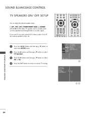
SOUND &LANGUAGE CONTROL TV SPEAKERS ON/ OFF SETUP You can be outputted even though there is no video signal. If you want to use your external hi-fi stereo system, turn off the internal speakers of the set. 7 LIST MENU 8 9 0 Q.VIEW EXIT OK INFO i GUIDE BACK VOL * PR FAV RATIO SLEEP SUBTITLE UPDATE BACK MENU INFO i EXIT GUIDE OK FAV VOL PR MUTE 1 2 3 1 Press the MENU button and then D or E button to select the AUDIO menu. 2 Press...
SOUND &LANGUAGE CONTROL TV SPEAKERS ON/ OFF SETUP You can be outputted even though there is no video signal. If you want to use your external hi-fi stereo system, turn off the internal speakers of the set. 7 LIST MENU 8 9 0 Q.VIEW EXIT OK INFO i GUIDE BACK VOL * PR FAV RATIO SLEEP SUBTITLE UPDATE BACK MENU INFO i EXIT GUIDE OK FAV VOL PR MUTE 1 2 3 1 Press the MENU button and then D or E button to select the AUDIO menu. 2 Press...

Owners Manual
Page 95
..., TV time is set by the time offset information based on Time Zone and GMT (Greenwich Mean Time) information which is received to broadcasting signal when time is displayed on the screen, followed by 10, 20, 30, 60, 90, 120, 180 and 240. SLEEP TIMER SETTING You don't have to remember to switch the set off , the set sleep time. 7 LIST MENU 8 9 0 Q.VIEW EXIT OK INFO i GUIDE BACK VOL * PR FAV RATIO SLEEP SUBTITLE UPDATE BACK MENU...
..., TV time is set by the time offset information based on Time Zone and GMT (Greenwich Mean Time) information which is received to broadcasting signal when time is displayed on the screen, followed by 10, 20, 30, 60, 90, 120, 180 and 240. SLEEP TIMER SETTING You don't have to remember to switch the set off , the set sleep time. 7 LIST MENU 8 9 0 Q.VIEW EXIT OK INFO i GUIDE BACK VOL * PR FAV RATIO SLEEP SUBTITLE UPDATE BACK MENU...


