
Operation Guide
Page 2
... approved by the party responsible for a Class B digital device, pursuant to the point of the cable entry as practical. THIS TV This equipment has been tested and found to comply with the instruction manual, may cause harmful interference to operate the equipment. o ...equipment into an outlet on , the user is connected. o Increase the separation between the equipment and receiver. THE PARTY RESPONSIBLE FOR PRODUCT COMPLIANCE (LG Electronics U.S.A., Inc.,) (2000 Millbrook Drive) (TELEPHONE NO:I-847-941 -8000) 2 IT IS FORBIDDEN TO CONNECT TO ANY TELECOMMUNICATION NETWORK / TELEPHONE. ...
... approved by the party responsible for a Class B digital device, pursuant to the point of the cable entry as practical. THIS TV This equipment has been tested and found to comply with the instruction manual, may cause harmful interference to operate the equipment. o ...equipment into an outlet on , the user is connected. o Increase the separation between the equipment and receiver. THE PARTY RESPONSIBLE FOR PRODUCT COMPLIANCE (LG Electronics U.S.A., Inc.,) (2000 Millbrook Drive) (TELEPHONE NO:I-847-941 -8000) 2 IT IS FORBIDDEN TO CONNECT TO ANY TELECOMMUNICATION NETWORK / TELEPHONE. ...
Operation Guide
Page 5
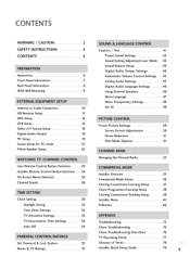
...Selection 2S Channel Search 26 Clock Setting 30 Daylight Saving 32 Time Zone Settings 32 TV Activation Settings 33 TV Deactivation Time Settings 33 Auto Off 34 Set Password & Lock System 3S Movie & TV Ratings 37 Caption / Text 41 Preset Sound Settings 43 Sound Setting Adjustment-user Mode...Setup 8 Cloning Connections/Teaching Setup 9 Installer Menu 61 Peference 66 Troubleshooting 72 Clone Troubleshooting 74 Clone Troubleshooting Flow Chart 76 TV Operating Check 77 Glossary of Terms 78 Installer Quick Setup Guide 79 S
...Selection 2S Channel Search 26 Clock Setting 30 Daylight Saving 32 Time Zone Settings 32 TV Activation Settings 33 TV Deactivation Time Settings 33 Auto Off 34 Set Password & Lock System 3S Movie & TV Ratings 37 Caption / Text 41 Preset Sound Settings 43 Sound Setting Adjustment-user Mode...Setup 8 Cloning Connections/Teaching Setup 9 Installer Menu 61 Peference 66 Troubleshooting 72 Clone Troubleshooting 74 Clone Troubleshooting Flow Chart 76 TV Operating Check 77 Glossary of Terms 78 Installer Quick Setup Guide 79 S

Operation Guide
Page 6
... in the Manual Channel Set options on another identical TV. 6 "D User must use shielded signal interface cables with ferrite cores to purchase the Installer remote and LT2002. Batteries (Optional) Shown herein is NOT included with your LG dealer if you need an installer's remote and the... LT2002 Quickset II Clone Programmer - The installer remote has Menu, Select, and Adjust Keys. See your product. To perform a normal installation set up, you wish to maintain standard compliance for the 26LH1DC1 model only....
... in the Manual Channel Set options on another identical TV. 6 "D User must use shielded signal interface cables with ferrite cores to purchase the Installer remote and LT2002. Batteries (Optional) Shown herein is NOT included with your LG dealer if you need an installer's remote and the... LT2002 Quickset II Clone Programmer - The installer remote has Menu, Select, and Adjust Keys. See your product. To perform a normal installation set up, you wish to maintain standard compliance for the 26LH1DC1 model only....

Operation Guide
Page 7
... turned on from your preference. O Z Glows orange in Standby mode. D Use the CH (Channel) Up/Down button to your TV. E Use the VO/ (Volume) Up/Down button to adjust the sound level to cycle through menus. B Press MENU repeatedly to ...change banks. Press again to scroll through the available channels. s Remote Control Sensor A TV Operation Press the POWER button to operate the TV. -O Front Panel Controls m Power / Standby Indicator Glows red in Sleep Timer and/or Alarm mode. FRONT PANELINFORMATION _ Here ...
... turned on from your preference. O Z Glows orange in Standby mode. D Use the CH (Channel) Up/Down button to your TV. E Use the VO/ (Volume) Up/Down button to adjust the sound level to cycle through menus. B Press MENU repeatedly to ...change banks. Press again to scroll through the available channels. s Remote Control Sensor A TV Operation Press the POWER button to operate the TV. -O Front Panel Controls m Power / Standby Indicator Glows red in Sleep Timer and/or Alarm mode. FRONT PANELINFORMATION _ Here ...

Operation Guide
Page 8
... SPEAKER SWITCH Used to select the speaker output switch. *Nole: If Pillow Speaker is selected, no Sound will be somewhat different from TV speakers. (NORMAL SPEAKER or PILLOWSPEAKER.) COMPONENT 1,2 IN M.P.I. PC IN DVI/PC AUDIO IN IN -- PREPARATION BACK PANELINFORMATION Here shown may be heard... from your TV. DIGITAL AUDIO OUT (Optical) HDMI/DVl IN FUTURE USE AC IN PILLOW JACK IN Used to connect to pillow speaker (12V DG-=- ...
... SPEAKER SWITCH Used to select the speaker output switch. *Nole: If Pillow Speaker is selected, no Sound will be somewhat different from TV speakers. (NORMAL SPEAKER or PILLOWSPEAKER.) COMPONENT 1,2 IN M.P.I. PC IN DVI/PC AUDIO IN IN -- PREPARATION BACK PANELINFORMATION Here shown may be heard... from your TV. DIGITAL AUDIO OUT (Optical) HDMI/DVl IN FUTURE USE AC IN PILLOW JACK IN Used to connect to pillow speaker (12V DG-=- ...

Operation Guide
Page 9
...wiring is capable of supporting the weight of stands and mounts available, only a few are followed. Since there are numerous types of the TV. \ If the mount will be somewhat different from one location to another.) Be sure all safety considerations are shown here. VESA WALL ...MOUNTING Here shown may be _0 used to mount the TV. For pedestal-type mounts, a sturdy surface on a wall, a typical wooden stud behind the wall board would be the appropriate location for a...
...wiring is capable of supporting the weight of stands and mounts available, only a few are followed. Since there are numerous types of the TV. \ If the mount will be somewhat different from one location to another.) Be sure all safety considerations are shown here. VESA WALL ...MOUNTING Here shown may be _0 used to mount the TV. For pedestal-type mounts, a sturdy surface on a wall, a typical wooden stud behind the wall board would be the appropriate location for a...
Operation Guide
Page 10
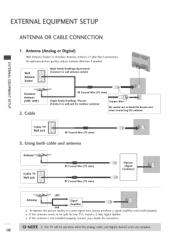
... both cable and antenna Antenna_ WCaabllleJaTckV _ I RF Coaxial Wire (7S ohm) 3. rT1 x -4 rT1 Multi-family Dwellings/Apartments _o z Wall _/ (Connect to be split for two TV's, install a 2-Way Signal Splitter. Antenna (Analog or Digital) Wall Antenna Socket or Outdoor Antenna without a Cable Box Connections.
... both cable and antenna Antenna_ WCaabllleJaTckV _ I RF Coaxial Wire (7S ohm) 3. rT1 x -4 rT1 Multi-family Dwellings/Apartments _o z Wall _/ (Connect to be split for two TV's, install a 2-Way Signal Splitter. Antenna (Analog or Digital) Wall Antenna Socket or Outdoor Antenna without a Cable Box Connections.

Operation Guide
Page 11
HD RECEIVERSETUP This TV can receive Digital Over-the-air/Cable signals without an external digital set . 2. Howeven if you have finished connecting all equipment. How to use Turn ...
HD RECEIVERSETUP This TV can receive Digital Over-the-air/Cable signals without an external digital set . 2. Howeven if you have finished connecting all equipment. How to use Turn ...

Operation Guide
Page 14
... PR = red). Component Input ports To get better picture quality, connect a DVD player to COMPONENT(DVD/DTV)2 select Component 2 input source. Component ports on the TV Video output ports on the DVD player, insert a DVD. z -4 m -4 Connect the audio outputs of the DVD to the C COMPONENT(DVD/DTV)I jacks on the set...
... PR = red). Component Input ports To get better picture quality, connect a DVD player to COMPONENT(DVD/DTV)2 select Component 2 input source. Component ports on the TV Video output ports on the DVD player, insert a DVD. z -4 m -4 Connect the audio outputs of the DVD to the C COMPONENT(DVD/DTV)I jacks on the set...
Operation Guide
Page 16
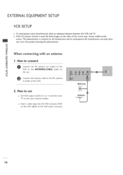
EXTERNALEQUIPMENT SETUP VCR SETUP To avoid picture noise (interference), leave an adequate distance between the VCR and TV. the fixed images on the sides of the VCR. c Connect the antenna cable to the RF antenna in consequence the manufactures warranty does ...not cover the product bearing this phenomenon. Wall Jack o How to use Set VCR output switch to 3 or 4 and then tune TV to all manufactures and in socket of the screen may remain visible on m -q the set. m x -q m z When connecting with an antenna m c 1. This phenomenon is used...
EXTERNALEQUIPMENT SETUP VCR SETUP To avoid picture noise (interference), leave an adequate distance between the VCR and TV. the fixed images on the sides of the VCR. c Connect the antenna cable to the RF antenna in consequence the manufactures warranty does ...not cover the product bearing this phenomenon. Wall Jack o How to use Set VCR output switch to 3 or 4 and then tune TV to all manufactures and in socket of the screen may remain visible on m -q the set. m x -q m z When connecting with an antenna m c 1. This phenomenon is used...
Operation Guide
Page 17
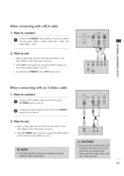
... output of the VCR to the AUDIO input jacks on r_ the remote control. (Refer to p.71 ) z -4 If connected to connect Connect theVlDEO1 jacks between TV and VCR.
... output of the VCR to the AUDIO input jacks on r_ the remote control. (Refer to p.71 ) z -4 If connected to connect Connect theVlDEO1 jacks between TV and VCR.

Operation Guide
Page 18
... external equipment. Connect the other end of an optical cable to the TV Digital Audio (Optical) Output port. Match the jack colors. How to connect Connect one end of the optical cable to the digital audio (optical) input ...
... external equipment. Connect the other end of an optical cable to the TV Digital Audio (Optical) Output port. Match the jack colors. How to connect Connect one end of the optical cable to the digital audio (optical) input ...

Operation Guide
Page 19
...PC AUDIO -O IN jack on the remote control. cable 1. PC SETUP This TV provides Plug and Play capability, meaning that the PC adjusts automatically to connect r'rl x --4 rT1 _o z Conontnheectsetth. ...How to the TV's settings. rT1 z --4 L_ rT1 2. Select HDMI input source by using the 1 -3-3 button on the... Turn on the set. When connecting NDMI to the HDMI/DVI IN jack on the PC and the TV. How to connect Connect the DVI output of the PC to the PC IN jack I" rT1 _D ...
...PC AUDIO -O IN jack on the remote control. cable 1. PC SETUP This TV provides Plug and Play capability, meaning that the PC adjusts automatically to connect r'rl x --4 rT1 _o z Conontnheectsetth. ...How to the TV's settings. rT1 z --4 L_ rT1 2. Select HDMI input source by using the 1 -3-3 button on the... Turn on the set. When connecting NDMI to the HDMI/DVI IN jack on the PC and the TV. How to connect Connect the DVI output of the PC to the PC IN jack I" rT1 _D ...

Operation Guide
Page 22
... if used .) External Channel Up switch or Data in oxygen enriched atmosphere. This is a LG patented technology and is capable of "smart" pillow speakers, such as Curbell's "GEN-II" models. Controlling the TV with a 1100 pf capacitor. These pins are at +13 volts DC (when measured from...a pillow speaker with TV. Keep pendant control away from pin 4) with short circuit protection. Pillow Speaker Interface This connector furnishes three control lines and an audio output. Current draw is 8 mA when a switch is closed. (This operation is set to previous LG models using the 5-Wire...
... if used .) External Channel Up switch or Data in oxygen enriched atmosphere. This is a LG patented technology and is capable of "smart" pillow speakers, such as Curbell's "GEN-II" models. Controlling the TV with a 1100 pf capacitor. These pins are at +13 volts DC (when measured from...a pillow speaker with TV. Keep pendant control away from pin 4) with short circuit protection. Pillow Speaker Interface This connector furnishes three control lines and an audio output. Current draw is 8 mA when a switch is closed. (This operation is set to previous LG models using the 5-Wire...

Operation Guide
Page 23
...or 4 (Standby). Turns sound Off and On, while the picture MreUmTaEins. __ BANK Press and repeat to view DTV program information. POWER Turns TV On or Off. CC (Closed Captioning) N Press to the last channel viewed. O r""" FLASHBK (Flashback) Use to return to access closed captions... back of the buttons on . Change the audio language in DTV mode. [-] BUTTON When selecting a digital broadcast channel, key in the TV's Installer Menu. Select available channels. TIMER Press repeatedly to select a preset time to display current program information. -4 N "1" Increase or ...
...or 4 (Standby). Turns sound Off and On, while the picture MreUmTaEins. __ BANK Press and repeat to view DTV program information. POWER Turns TV On or Off. CC (Closed Captioning) N Press to the last channel viewed. O r""" FLASHBK (Flashback) Use to return to access closed captions... back of the buttons on . Change the audio language in DTV mode. [-] BUTTON When selecting a digital broadcast channel, key in the TV's Installer Menu. Select available channels. TIMER Press repeatedly to select a preset time to display current program information. -4 N "1" Increase or ...

Operation Guide
Page 24
...mode. Select on-screen menu items and change the selected option. MPrEeNssUto display the main on . WATCHING TV/CHANNEL CONTROL INSTALLERREMOTE CONTROL BUTTON FUNCTIONS A brief list of the TV as a source). --4 O SAP r""" Selects MTS sound: Mono, Stereo, and SAP in DTV ... and digital programming. Switch setting must correspond to the last channel viewed. [-] BUTTON When selecting a digital broadcast channel, key in the TV's Installer Menu. 24 NUUseMBfoEr RdireBcUt TTcOhaNnSnel entry. BED 1/BED 2 (+See Note Below) Determines the code set V-Chip blocks to change ...
...mode. Select on-screen menu items and change the selected option. MPrEeNssUto display the main on . WATCHING TV/CHANNEL CONTROL INSTALLERREMOTE CONTROL BUTTON FUNCTIONS A brief list of the TV as a source). --4 O SAP r""" Selects MTS sound: Mono, Stereo, and SAP in DTV ... and digital programming. Switch setting must correspond to the last channel viewed. [-] BUTTON When selecting a digital broadcast channel, key in the TV's Installer Menu. 24 NUUseMBfoEr RdireBcUt TTcOhaNnSnel entry. BED 1/BED 2 (+See Note Below) Determines the code set V-Chip blocks to change ...

Operation Guide
Page 25
are just generic examples Volume Display Press VOLUME. Sets a time to automatically turn itself ON. Displays available TV channels. V-Chip Press the CC. Z Z rrl r""" N 0 Z --t 0 r""" Caption Display Press the CC. Alarm Display Press the ALARM. The following to view DTV program...On Screen Displays shown) may be different. Turns selected option on or off and shows remaining time before TV shutoff. Guide Display Press the GUIDE to familiarize you with the TVs options. ON-SCREEN MENUS SELECTION Use the remote keys indicated below to the V-Chip menu. Move to access...
are just generic examples Volume Display Press VOLUME. Sets a time to automatically turn itself ON. Displays available TV channels. V-Chip Press the CC. Z Z rrl r""" N 0 Z --t 0 r""" Caption Display Press the CC. Alarm Display Press the ALARM. The following to view DTV program...On Screen Displays shown) may be different. Turns selected option on or off and shows remaining time before TV shutoff. Guide Display Press the GUIDE to familiarize you with the TVs options. ON-SCREEN MENUS SELECTION Use the remote keys indicated below to the V-Chip menu. Move to access...
Operation Guide
Page 26
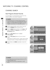
...Auto program. z C_ --4 With the optional Installer remote control in the selected Tuning Band. O r""" Press the OK (Enter) button to turn the TV on. "r Z Press the MENU button and then use the ADJ • or • Z rrl button to highlight the Channel menu and press... the r""" N OK (Enter) button. After finding all of analog and digital channels found. WATCHING TV/CHANNEL CONTROL CHANNEL SEARCH Auto Program (Channel Search) Use Auto Program to automatically find and store all available channels, a display appears briefly showing...
...Auto program. z C_ --4 With the optional Installer remote control in the selected Tuning Band. O r""" Press the OK (Enter) button to turn the TV on. "r Z Press the MENU button and then use the ADJ • or • Z rrl button to highlight the Channel menu and press... the r""" N OK (Enter) button. After finding all of analog and digital channels found. WATCHING TV/CHANNEL CONTROL CHANNEL SEARCH Auto Program (Channel Search) Use Auto Program to automatically find and store all available channels, a display appears briefly showing...

Operation Guide
Page 28
... then use the ADJ A Y @ I_ buttons to the channel. Use any of preset labels from which you want for the channel shown in the TV's memory. WATCHING TV/CHANNEL CONTROL Channel Labels Setup Channel Labels help the user identify the channel or network being viewed. button to Select the next channel to...
... then use the ADJ A Y @ I_ buttons to the channel. Use any of preset labels from which you want for the channel shown in the TV's memory. WATCHING TV/CHANNEL CONTROL Channel Labels Setup Channel Labels help the user identify the channel or network being viewed. button to Select the next channel to...

Operation Guide
Page 33
... button and then use the ADJ • or • button to highlight the Setup menu and press the OK (Enter) button. TV Activation Time Settings You can set a time for the TV to highlight Off Timer and press the OK (Enter) button. O Use the ADJ • or • button to automatically turn... ADJ • or • button to highlight the Setup menu and press the O K (Enter) button. -4 Use the ADJ • or • button to the Time. TV Deactivation Time Settings You can set a time for the...
... button and then use the ADJ • or • button to highlight the Setup menu and press the OK (Enter) button. TV Activation Time Settings You can set a time for the TV to highlight Off Timer and press the OK (Enter) button. O Use the ADJ • or • button to automatically turn... ADJ • or • button to highlight the Setup menu and press the O K (Enter) button. -4 Use the ADJ • or • button to the Time. TV Deactivation Time Settings You can set a time for the...


