
Owners Manual
Page 1
number before operating See the [abel attached this information on the back cover and quote to your set . when you require ENERGY guidelines STAR is a set of the set . S. A.,[nc. LCD TV OWNER'S MANUAL LCD TV MODELS 26LC7D 26LC7DC 32LC4D 42LC4D Please read this manual carefully your dealer service. Retain it for energy efficiency. Agency(EPA). and serial number of power-saving issued by the U.S. Protection Environmental As an ENERGY STAR Partner LGE U. has determined that this product meets the ENERGY STAR guidelines for future Record model reference.
number before operating See the [abel attached this information on the back cover and quote to your set . when you require ENERGY guidelines STAR is a set of the set . S. A.,[nc. LCD TV OWNER'S MANUAL LCD TV MODELS 26LC7D 26LC7DC 32LC4D 42LC4D Please read this manual carefully your dealer service. Retain it for energy efficiency. Agency(EPA). and serial number of power-saving issued by the U.S. Protection Environmental As an ENERGY STAR Partner LGE U. has determined that this product meets the ENERGY STAR guidelines for future Record model reference.
Owners Manual
Page 2
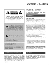
... provides guidelines proper grounding and, in a particular installation. However, there is connected. -Consult technician the dealer or an experienced radio/TV for compliance could void the user's that the system to operate this equipment by one or more of the cable entry modification could ...the receiver is no guarantee that interference will not occur in particular, as close to correct off and on a circuit different from LG Electronics. shall be determined the equipment to try to the point specifies cable ground as practical. This equipment generates, uses and can...
... provides guidelines proper grounding and, in a particular installation. However, there is connected. -Consult technician the dealer or an experienced radio/TV for compliance could void the user's that the system to operate this equipment by one or more of the cable entry modification could ...the receiver is no guarantee that interference will not occur in particular, as close to correct off and on a circuit different from LG Electronics. shall be determined the equipment to try to the point specifies cable ground as practical. This equipment generates, uses and can...
Owners Manual
Page 5
...- User Mode ...46 XD - Add / Delete Channel (Manual Scan) ...35 4 Preset...44 44 45 46 47 ...2 ...6 6 Feature of this TV ... _i+++i+++ ++_iii iiii iiii iiii iiii iiii iiii iiii iiii iiii iiii iiii iiii iiii iiii iiii iiii iiii iiii iiii iiii iiii iiii ii...!+_+ Accessories ...Front Panel Information ...Back Panel Information ...7 8 10 Back Cover for Wire Arrangement ...12 Attaching the TV to a Wall ...Stand Installation ...VESA Wall Mounting ...13 14 15 Manual Picture Adjustment ...- Channel Editing ...DTV Signal Strength ...Input Source Selection ......
...- User Mode ...46 XD - Add / Delete Channel (Manual Scan) ...35 4 Preset...44 44 45 46 47 ...2 ...6 6 Feature of this TV ... _i+++i+++ ++_iii iiii iiii iiii iiii iiii iiii iiii iiii iiii iiii iiii iiii iiii iiii iiii iiii iiii iiii iiii iiii iiii iiii ii...!+_+ Accessories ...Front Panel Information ...Back Panel Information ...7 8 10 Back Cover for Wire Arrangement ...12 Attaching the TV to a Wall ...Stand Installation ...VESA Wall Mounting ...13 14 15 Manual Picture Adjustment ...- Channel Editing ...DTV Signal Strength ...Input Source Selection ......
Owners Manual
Page 6
Programming the Remote Control ...77 IR Codes ...80 External Control Through RS-232C ...82 5 Auto Clock Setup ...- Manual Clock Setup ...Auto On/Off Timer Setting ...Sleep Timer Setting ...Auto Shut-off Setting ...62 63 64 65 66 Set Password & Lock System ...Channel Blocking ...External Input Blocking ...Movie & TV Rating ... 67 69 69 70 !!Ii i iiiiiiiiiiiiii i i i i i i ii i i i i i i i i i i i i i i i i i i i i i i i i i i i i i i i i i i i i i i 73 75 76 Troubleshooting ...Maintenance ...Product Specifications ... Clock Setting ...62 -
Programming the Remote Control ...77 IR Codes ...80 External Control Through RS-232C ...82 5 Auto Clock Setup ...- Manual Clock Setup ...Auto On/Off Timer Setting ...Sleep Timer Setting ...Auto Shut-off Setting ...62 63 64 65 66 Set Password & Lock System ...Channel Blocking ...External Input Blocking ...Movie & TV Rating ... 67 69 69 70 !!Ii i iiiiiiiiiiiiii i i i i i i ii i i i i i i i i i i i i i i i i i i i i i i i i i i i i i i i i i i i i i i 73 75 76 Troubleshooting ...Maintenance ...Product Specifications ... Clock Setting ...62 -
Owners Manual
Page 7
... mercury. This is normal, there is turned on the monitor's Avoid touching the LCD screen or holding your local authority. 6 against as tiny red, green, or blue spots. [ DU FEATURE OF THIS TV LG's own special digital image generator, consisting of "Dolby "and the doubie-D Doiby ...carried out in this product c. The fluorescent a small amount waste. With HDMI CEC support of LG's audio/video device csImPLInK connected to the HDMI (high-definition multimedia interface), LG TV with this product with general household must be a small "flicker" when it for long periods ...
... mercury. This is normal, there is turned on the monitor's Avoid touching the LCD screen or holding your local authority. 6 against as tiny red, green, or blue spots. [ DU FEATURE OF THIS TV LG's own special digital image generator, consisting of "Dolby "and the doubie-D Doiby ...carried out in this product c. The fluorescent a small amount waste. With HDMI CEC support of LG's audio/video device csImPLInK connected to the HDMI (high-definition multimedia interface), LG TV with this product with general household must be a small "flicker" when it for long periods ...

Owners Manual
Page 9
And then wipe the product with a cloth (If a polishing cloth is included with your product has a protection tape attached, remove the tape. blinks green and is turned then illuminates on, the indicator green before the picture 8 use it). ""_ NOTE: If your product, _D m _D Front Panel Controls (26 inches) © z (A,¥)Bu_ons (41,I_) Buttons Bu_on Bu_on Remote Control Sensor Power/Sta Illuminates nd by Indicator red in standby mode. When the TV is displayed. PREPARATION FRONT PANELINFORMATION Here shown may be somewhat different from your TV.
And then wipe the product with a cloth (If a polishing cloth is included with your product has a protection tape attached, remove the tape. blinks green and is turned then illuminates on, the indicator green before the picture 8 use it). ""_ NOTE: If your product, _D m _D Front Panel Controls (26 inches) © z (A,¥)Bu_ons (41,I_) Buttons Bu_on Bu_on Remote Control Sensor Power/Sta Illuminates nd by Indicator red in standby mode. When the TV is displayed. PREPARATION FRONT PANELINFORMATION Here shown may be somewhat different from your TV.

Owners Manual
Page 10
When the TV is turned on, the indicator then illuminates blinks green and green before the picture is displayed. 9 -0 _o m Front Panel Controls (32/42 inches) _o © 7 (A,V)Buttons (_I,I_) Buttons Button Button Button Button Remote Control Sensor Power/Sta nd by Indicator llluminates red in standby mode.
When the TV is turned on, the indicator then illuminates blinks green and green before the picture is displayed. 9 -0 _o m Front Panel Controls (32/42 inches) _o © 7 (A,V)Buttons (_I,I_) Buttons Button Button Button Button Remote Control Sensor Power/Sta nd by Indicator llluminates red in standby mode.
Owners Manual
Page 11
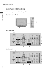
PREPARATION BACK PANELINFORMATION ,,,iHere shown may be somewhat different from your TV. -O m Back Connection Panel © z _@ _I 26/32 inches model 42 inches model 10
PREPARATION BACK PANELINFORMATION ,,,iHere shown may be somewhat different from your TV. -O m Back Connection Panel © z _@ _I 26/32 inches model 42 inches model 10
Owners Manual
Page 12
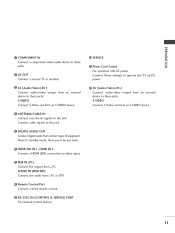
HDMI/DVI Connect IN 1, HDMI IN 2 to operate the TV on DC AV OUT Connect a second TV or monitor. AUDIO IN (RGB/DVI) Connect the audio from an S-VIDEO device. Note: In standby mode, these @ SERVICE © z a component Power Cord Socket For ...
HDMI/DVI Connect IN 1, HDMI IN 2 to operate the TV on DC AV OUT Connect a second TV or monitor. AUDIO IN (RGB/DVI) Connect the audio from an S-VIDEO device. Note: In standby mode, these @ SERVICE © z a component Power Cord Socket For ...
Owners Manual
Page 13
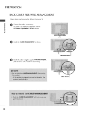
PREPARATION BACK COVERFORWIREARRANGEMENT ,,,_ Here shown may be somewhat different from your TV. _D m _D Connect the cables as shown. CABLE MANAGEMENT Bundle the cables using the supplied TWISTER HOLDER. (This feature is not available for all models.) TWIST HOLDER IIII 12 To connect an additional equipment, see the EXTERNAL EQUIPMENT SETUP section. © z @ Install the CABLE MANAGEMENT as necessary.
PREPARATION BACK COVERFORWIREARRANGEMENT ,,,_ Here shown may be somewhat different from your TV. _D m _D Connect the cables as shown. CABLE MANAGEMENT Bundle the cables using the supplied TWISTER HOLDER. (This feature is not available for all models.) TWIST HOLDER IIII 12 To connect an additional equipment, see the EXTERNAL EQUIPMENT SETUP section. © z @ Install the CABLE MANAGEMENT as necessary.
Owners Manual
Page 14
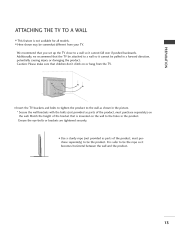
...the product, must purchase separately) the wall. It is not available for all models. that you set up the TV close to a wall so it cannot fall over if pushed backwards. ATTACHINGTHE TV TO A WALL ,,,I This feature is safer to tie the rope so it cannot be attached to a wall ...0,_ Use a sturdy rope (not provided as shown in a forward direction, we recommend _D potentially causing injury or damaging the product. from the TV. © z Insert the TV brackets and bolts to tighten the product to the wall as parts of the product, must purchase separately) to tie the product. on or...
...the product, must purchase separately) the wall. It is not available for all models. that you set up the TV close to a wall so it cannot fall over if pushed backwards. ATTACHINGTHE TV TO A WALL ,,,I This feature is safer to tie the rope so it cannot be attached to a wall ...0,_ Use a sturdy rope (not provided as shown in a forward direction, we recommend _D potentially causing injury or damaging the product. from the TV. © z Insert the TV brackets and bolts to tighten the product to the wall as parts of the product, must purchase separately) to tie the product. on or...

Owners Manual
Page 17
Cable Cable TV Wall Jack I Single-family Dwellings/Houses • / (Connect to wire connecting antenna. 2. For optimum O z picture quality, adjust antenna direction if needed. _ Multi-family Dwellings/Apartments ... properly. needs to be split for outdoor __ _ ._..._S Copper Wire Be careful when ...bend the the bronze antenna) not to wall jack for two TV's, install a 2-Way Signal Splitter. Antenna m (Analog or Digital) Antenna without a Cable Box Wall Antenna Socket or Outdoor Connections. is not installed properly, contact your dealer...
Cable Cable TV Wall Jack I Single-family Dwellings/Houses • / (Connect to wire connecting antenna. 2. For optimum O z picture quality, adjust antenna direction if needed. _ Multi-family Dwellings/Apartments ... properly. needs to be split for outdoor __ _ ._..._S Copper Wire Be careful when ...bend the the bronze antenna) not to wall jack for two TV's, install a 2-Way Signal Splitter. Antenna m (Analog or Digital) Antenna without a Cable Box Wall Antenna Socket or Outdoor Connections. is not installed properly, contact your dealer...
Owners Manual
Page 18
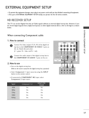
... the owner's manual for the 42 inches models. IN2 input, select Yes Yes Yes Yes Yes No Yes Yes Yes Yes 17 HD RECEIVERSETUP This TV can receive Digital do receive digital below. How to connect Connect Component cable _D z m XD c (Y, PB, PR) of the digital set-top the COMPONENT IN...
... the owner's manual for the 42 inches models. IN2 input, select Yes Yes Yes Yes Yes No Yes Yes Yes Yes 17 HD RECEIVERSETUP This TV can receive Digital do receive digital below. How to connect Connect Component cable _D z m XD c (Y, PB, PR) of the digital set-top the COMPONENT IN...
Owners Manual
Page 21
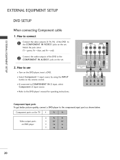
... on the DVD playen insert a DVD. 01_ Select Component 1 input source by using the INPUT button on DVD player 20 instructions. Component ports on the TV Video output ports on the remote control. 01_ If connected Component to the jacks on the set . XD c Connect the audio outputs IN of the...
... on the DVD playen insert a DVD. 01_ Select Component 1 input source by using the INPUT button on DVD player 20 instructions. Component ports on the TV Video output ports on the remote control. 01_ If connected Component to the jacks on the set . XD c Connect the audio outputs IN of the...

Owners Manual
Page 23
... VCR owner's manual.) 22 EXTERNALEQUIPMENT SETUP VCR SETUP To avoid picture If the 4:5 picture noise (interference), format leave an adequate distance between the VCR and TV. This phenomenon does not cover the product m x .-t m When connecting with an antenna z m JC) c m z .-t m c Wall Jack Antenna 1. IN socket on the... is used; How to use 01_ Set VCR output switch to 3 or 4 and then tune TV to the same channel number. 01_ Insert a video tape into the VCR and press PLAY on the VCR. (Refer to the RF antenna 2. and in...
... VCR owner's manual.) 22 EXTERNALEQUIPMENT SETUP VCR SETUP To avoid picture If the 4:5 picture noise (interference), format leave an adequate distance between the VCR and TV. This phenomenon does not cover the product m x .-t m When connecting with an antenna z m JC) c m z .-t m c Wall Jack Antenna 1. IN socket on the... is used; How to use 01_ Set VCR output switch to 3 or 4 and then tune TV to the same channel number. 01_ Insert a video tape into the VCR and press PLAY on the VCR. (Refer to the RF antenna 2. and in...
Owners Manual
Page 24
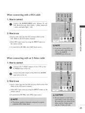
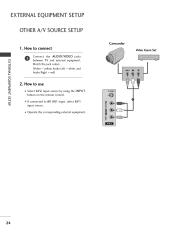
... control. 01_ If connected to the AUDIO input jacks on the set . 2. How to connect Connect S-VIDEO with a RCA cable the AUDIO/VIDEO jacks between TV and Left m VCR. Connect the audio outputs of the VCR to connect Connect with an S-Video cable the S-VIDEO output of the VCR to AV...
... control. 01_ If connected to the AUDIO input jacks on the set . 2. How to connect Connect S-VIDEO with a RCA cable the AUDIO/VIDEO jacks between TV and Left m VCR. Connect the audio outputs of the VCR to connect Connect with an S-Video cable the S-VIDEO output of the VCR to AV...
Owners Manual
Page 25
...!ii!ii!ii!ii!ii!ii!ii!ii!ii!ii!iiiii!ii_! 24 How to connect Connect m Video Game Set AUDIO/VIDEO jacks the x m between TV and external equipment.
...!ii!ii!ii!ii!ii!ii!ii!ii!ii!ii!iiiii!ii_! 24 How to connect Connect m Video Game Set AUDIO/VIDEO jacks the x m between TV and external equipment.
Owners Manual
Page 26
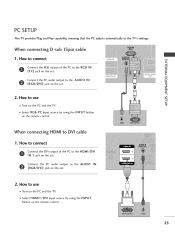
... remote control. button m c When connecting I . How to use 01_ Turn on the PC and the TV. 01_ Select HDMII/DVI input source by using the INPUT button on the set . PC SETUP This TV provides Plug and Play capability, meaning that the PC adjusts automatically to the AUDIO IN m z p.- When ...connecting I . to the TV's settings. Connect (RGB/DVI) the PC audio output to use 01_ Turn on the PC and the TV. 01_ Select RGB-PC input source by using the INPUT on the set . 2. How to the AUDIO...
... remote control. button m c When connecting I . How to use 01_ Turn on the PC and the TV. 01_ Select HDMII/DVI input source by using the INPUT button on the set . PC SETUP This TV provides Plug and Play capability, meaning that the PC adjusts automatically to the AUDIO IN m z p.- When ...connecting I . to the TV's settings. Connect (RGB/DVI) the PC audio output to use 01_ Turn on the PC and the TV. 01_ Select RGB-PC input source by using the INPUT on the set . 2. How to the AUDIO...
Owners Manual
Page 29
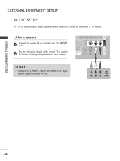
How to the TV's AV OUT z See the Operating m Manual of the second TV or monitor _D c for further details regarding that device's input settings. m z m c 28 the second TV or monitor to connect m x m Connect jacks. EXTERNALEQUIPMENT SETUP AV OUT SETUP The TV has a speda[ signal output capability which allows you to hook up the second TV or monitor. 1.
How to the TV's AV OUT z See the Operating m Manual of the second TV or monitor _D c for further details regarding that device's input settings. m z m c 28 the second TV or monitor to connect m x m Connect jacks. EXTERNALEQUIPMENT SETUP AV OUT SETUP The TV has a speda[ signal output capability which allows you to hook up the second TV or monitor. 1.
Owners Manual
Page 30
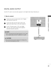
I. How to connect x Connect one end of the optical audio (optical) input on the audio equipment. XD c Set the "TV Speaker option - See the external audio equipment instruction manual for operation. c @ 29 DiGiTAL AUDIO OUTPUT Send the TV's audio to the TV Digital Output port. rT1 Audio (Optical) _D z cable to the rT1 Connect digital the other end of an optical cable to external audio equipment via the Digital Audio Output (Optical) port. Off" in the AUDIO rT1 z rT1 menu. (_ p.55).
I. How to connect x Connect one end of the optical audio (optical) input on the audio equipment. XD c Set the "TV Speaker option - See the external audio equipment instruction manual for operation. c @ 29 DiGiTAL AUDIO OUTPUT Send the TV's audio to the TV Digital Output port. rT1 Audio (Optical) _D z cable to the rT1 Connect digital the other end of an optical cable to external audio equipment via the Digital Audio Output (Optical) port. Off" in the AUDIO rT1 z rT1 menu. (_ p.55).


