
Instruction Manual
Page 3
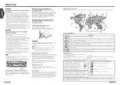
... the audio can be dangerous to your Kenwood dealer. Called lens fogging, discs may represent something impossible in actual operation. Time is securely installed. Reset button Screen brightness during low temperatures When the temperature of the unit falls such as it may differ from the KVT-815DVD/745DVD/715DVD Receiver (in November of 2003...
... the audio can be dangerous to your Kenwood dealer. Called lens fogging, discs may represent something impossible in actual operation. Time is securely installed. Reset button Screen brightness during low temperatures When the temperature of the unit falls such as it may differ from the KVT-815DVD/745DVD/715DVD Receiver (in November of 2003...
Instruction Manual
Page 46
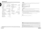
...-3, ISHIKAWA-CHO, HACHIOJI-SHI TOKYO, JAPAN KENWOOD CORP. Changes or modifications to this equipment does cause harmful interference to radio or television reception, which the receiver is not installed and used in the instruction manual. These limits are designed ...relating to provide reasonable protection against harmful interference in hazardous radiation exposure. This equipment may result in a residential installation. This product incorporates copyright protection technology that to which can be authorized by Macrovision. English Specifications Specifications subject to...
...-3, ISHIKAWA-CHO, HACHIOJI-SHI TOKYO, JAPAN KENWOOD CORP. Changes or modifications to this equipment does cause harmful interference to radio or television reception, which the receiver is not installed and used in the instruction manual. These limits are designed ...relating to provide reasonable protection against harmful interference in hazardous radiation exposure. This equipment may result in a residential installation. This product incorporates copyright protection technology that to which can be authorized by Macrovision. English Specifications Specifications subject to...

Installation Manual
Page 1
KVT-815DVD KVT-745DVD KVT-715DVD MONITOR WITH DVD RECEIVER INSTALLATION MANUAL MONITEUR AVEC RÉCEPTEUR DVD MANUEL D'INSTALLATION MONITOR CON RECEPTOR DVD MANUAL DE INSTALACIÓN MONITOR COM RECEPTOR DVD MANUAL DE INSTALAÇÃO © PRINTED IN JAPAN B54-4433-00/00 (K)(AI)
KVT-815DVD KVT-745DVD KVT-715DVD MONITOR WITH DVD RECEIVER INSTALLATION MANUAL MONITEUR AVEC RÉCEPTEUR DVD MANUEL D'INSTALLATION MONITOR CON RECEPTOR DVD MANUAL DE INSTALACIÓN MONITOR COM RECEPTOR DVD MANUAL DE INSTALAÇÃO © PRINTED IN JAPAN B54-4433-00/00 (K)(AI)
Installation Manual
Page 2
English Before Installation Accessories 1 2 3 4 5 6 7 8 ..........1 9 ..........1 0 ..........1 - ..........1 = ..........1 ..........2 ..........4 ..........4 ..........2 ..........2 ..........4 ..........4 2 English
English Before Installation Accessories 1 2 3 4 5 6 7 8 ..........1 9 ..........1 0 ..........1 - ..........1 = ..........1 ..........2 ..........4 ..........4 ..........2 ..........2 ..........4 ..........4 2 English
Installation Manual
Page 3
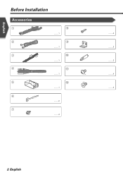
... the - connector to the unit. 6. battery. 8. The unit may cause a short circuit, that the mounting angle is installed, check whether the brake lamps, blinkers, wipers, etc. Installation Procedure 1. If you may be turned on the car are being connected to the system, connect the connectors either to both... touching to which they correspond. on and off with vinyl tape or other similar material. Install the unit in turn may die. • If the console has a lid, make sure to install the unit so that can be damaged or fail to work if you connect the + connector...
... the - connector to the unit. 6. battery. 8. The unit may cause a short circuit, that the mounting angle is installed, check whether the brake lamps, blinkers, wipers, etc. Installation Procedure 1. If you may be turned on the car are being connected to the system, connect the connectors either to both... touching to which they correspond. on and off with vinyl tape or other similar material. Install the unit in turn may die. • If the console has a lid, make sure to install the unit so that can be damaged or fail to work if you connect the + connector...
Installation Manual
Page 7
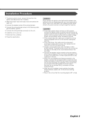
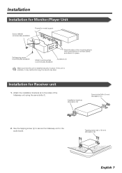
If the unit is installed securely in place. Tapping screw (ø4 × 16 mm) (Accessory 8) English 7 Use the tapping screw 8 to secure the hideaway unit to the ... (commercially available) Accessory 5 Make sure that the unit is unstable, it in place. Attach the installation brackets 9 to the audio board. Installation brackets (Accessory 9) Sems bolts (M4 × 8 mm) (Accessory 7) 2. Installation Installation for Receiver unit 1. Installation for Monitor/Player Unit Screw (M4X8) (commercially available) Firewall or metal support Self-tapping screw (commercially...
If the unit is installed securely in place. Tapping screw (ø4 × 16 mm) (Accessory 8) English 7 Use the tapping screw 8 to secure the hideaway unit to the ... (commercially available) Accessory 5 Make sure that the unit is unstable, it in place. Attach the installation brackets 9 to the audio board. Installation brackets (Accessory 9) Sems bolts (M4 × 8 mm) (Accessory 7) 2. Installation Installation for Receiver unit 1. Installation for Monitor/Player Unit Screw (M4X8) (commercially available) Firewall or metal support Self-tapping screw (commercially...

Installation Manual
Page 8
or = Bracket Screws (included in audio unit package) 8 English or = Screws (included in audio unit package) Audio unit or others Accessory - English Installation Installing in Japanese-Made Cars ■ Installing on Toyota, Nissan or Mitsubishi Car Using Brackets at Holes shown by "¶" or Accessory -
or = Bracket Screws (included in audio unit package) 8 English or = Screws (included in audio unit package) Audio unit or others Accessory - English Installation Installing in Japanese-Made Cars ■ Installing on Toyota, Nissan or Mitsubishi Car Using Brackets at Holes shown by "¶" or Accessory -

Installation Manual
Page 9
...) English 9 Accessory - Accessory 0 Accessory Screws (included in audio unit package) 3. Use a flat-blade screwdriver or pliers, and bend each accessory tab into the hole of installation bracket to fix the bracket. Use accessories 0 at each end of the right and left unit sides. Bend each side. ■...; Installation on Toyota Car using Brackets at Holes shown by "¶" or When using accessories 0 as shown. If so, tighten the bracket using the bracket shown ...
...) English 9 Accessory - Accessory 0 Accessory Screws (included in audio unit package) 3. Use a flat-blade screwdriver or pliers, and bend each accessory tab into the hole of installation bracket to fix the bracket. Use accessories 0 at each end of the right and left unit sides. Bend each side. ■...; Installation on Toyota Car using Brackets at Holes shown by "¶" or When using accessories 0 as shown. If so, tighten the bracket using the bracket shown ...
Installation Manual
Page 10
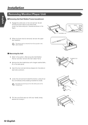
... the removal tool 6 and remove the two locks on the removal tool. 5. Be careful to avoid injury from the top side in the figure. 2. English Installation Removing Monitor/Player Unit ■ Removing the Hard Rubber Frame (escutcheon) 1. Lower the frame and pull it . Insert the two removal tools 6 deeply into the...
... the removal tool 6 and remove the two locks on the removal tool. 5. Be careful to avoid injury from the top side in the figure. 2. English Installation Removing Monitor/Player Unit ■ Removing the Hard Rubber Frame (escutcheon) 1. Lower the frame and pull it . Insert the two removal tools 6 deeply into the...


