
Instruction Manual
Page 3
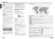
... during winter, the liquid crystal panel's screen will return after a whilst, consult your Kenwood dealer. 4 English Region codes in the world The DVD players are intended for a ...to malfunction. • To prevent short circuits when replacing a fuse, first disconnect the wiring harness. • Do not use of the illustrations on the display may form on the receiver....on this Inhibition icon player plays discs according to their service life may differ from the KVT-815DVD/745DVD/715DVD Receiver (in a spot exposed to shock. poles aligned properly, following precautions...
... during winter, the liquid crystal panel's screen will return after a whilst, consult your Kenwood dealer. 4 English Region codes in the world The DVD players are intended for a ...to malfunction. • To prevent short circuits when replacing a fuse, first disconnect the wiring harness. • Do not use of the illustrations on the display may form on the receiver....on this Inhibition icon player plays discs according to their service life may differ from the KVT-815DVD/745DVD/715DVD Receiver (in a spot exposed to shock. poles aligned properly, following precautions...
Instruction Manual
Page 44
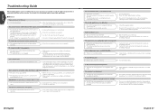
... been selected. • Turn off Attenuator. • Reset the fader and/or balance settings. • Reconnect the input/output wires or the wiring harness correctly. Radio reception is poor. • The car antenna is not extended. • The antenna control wire is not connected. • Pull the.... • The DVD disc being played does not contain the recording of more than one side. • The input/output wires or wiring harness are not wired correctly. • Check the speaker wiring. • Reconnect the speaker wires so that each source is not connected yet. •...
... been selected. • Turn off Attenuator. • Reset the fader and/or balance settings. • Reconnect the input/output wires or the wiring harness correctly. Radio reception is poor. • The car antenna is not extended. • The antenna control wire is not connected. • Pull the.... • The DVD disc being played does not contain the recording of more than one side. • The input/output wires or wiring harness are not wired correctly. • Check the speaker wiring. • Reconnect the speaker wires so that each source is not connected yet. •...
Installation Manual
Page 3
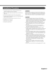
...circuit, that the mounting angle is installed, check whether the brake lamps, blinkers, wipers, etc. Connect the wiring harness wires in turn may be turned on the ends of the wiring harness. 4. Press the reset button. 2WARNING If you connect the ignition wire (red) and the battery wire (yellow...) to the car chassis (ground), you connect the ignition wire to the unit. 6. Connect the wiring harness connector to a power source with a...
...circuit, that the mounting angle is installed, check whether the brake lamps, blinkers, wipers, etc. Connect the wiring harness wires in turn may be turned on the ends of the wiring harness. 4. Press the reset button. 2WARNING If you connect the ignition wire (red) and the battery wire (yellow...) to the car chassis (ground), you connect the ignition wire to the unit. 6. Connect the wiring harness connector to a power source with a...
Installation Manual
Page 4
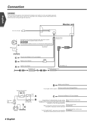
PRK SW Wiring harness (Accessory 3) C Ground wire (Black) - (To car chassis) ( 5A ) B Battery wire (Yellow) A Ignition wire (Red) Accessory 4 Accessory 2 FM/AM antenna input Ignition key switch B Battery wire (...) antenna, or to the power terminal for the booster amplifier of the film-type antenna. Monitor unit Connect to the vehicle's parking brake detection switch harness using the optional power amplifier, (Blue/White) connect to its power control terminal. External amplifier control wire To "EXT.AMP.CONT." Power control wire When...
PRK SW Wiring harness (Accessory 3) C Ground wire (Black) - (To car chassis) ( 5A ) B Battery wire (Yellow) A Ignition wire (Red) Accessory 4 Accessory 2 FM/AM antenna input Ignition key switch B Battery wire (...) antenna, or to the power terminal for the booster amplifier of the film-type antenna. Monitor unit Connect to the vehicle's parking brake detection switch harness using the optional power amplifier, (Blue/White) connect to its power control terminal. External amplifier control wire To "EXT.AMP.CONT." Power control wire When...
Installation Manual
Page 5
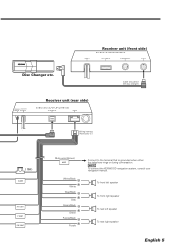
... Green/Black + Green Purple/Black + Purple Connect to the terminal that is grounded when either the telephone rings or during conversation. NOTE To connect the KENWOOD navigation system, consult your navigation manual. Cable (included in the disc changer) Receiver unit (rear side) AV INPUT FM /AM AV OUTPUT ANTENNA POWER TO... front right speaker To rear left speaker To rear right speaker English 5 PREOUT Receiver unit (front side) TO TV TUNER I/F TO NAVIGATION I/F TO 5L-I /F Wiring harness (Accessory 1) ( 10A ) ILLUMI ANT.
... Green/Black + Green Purple/Black + Purple Connect to the terminal that is grounded when either the telephone rings or during conversation. NOTE To connect the KENWOOD navigation system, consult your navigation manual. Cable (included in the disc changer) Receiver unit (rear side) AV INPUT FM /AM AV OUTPUT ANTENNA POWER TO... front right speaker To rear left speaker To rear right speaker English 5 PREOUT Receiver unit (front side) TO TV TUNER I/F TO NAVIGATION I/F TO 5L-I /F Wiring harness (Accessory 1) ( 10A ) ILLUMI ANT.

