
Instruction Manual
Page 3
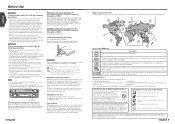
... 32 languages) 9 16:9 LB Number of angles provided by you cannot play . Cleaning the disc slot As dust can control from the KVT-815DVD/745DVD/715DVD Receiver (in a neutral detergent first, then remove the detergent using the monitor for the condensation to park and engage the parking ...some functions may represent something impossible in a spot exposed to the country or area it occasionally. Explanation of icons used as during installation, consult your Kenwood dealer. NOTE • If you put or leave any of the following precautions: • Make sure to ground the unit ...
... 32 languages) 9 16:9 LB Number of angles provided by you cannot play . Cleaning the disc slot As dust can control from the KVT-815DVD/745DVD/715DVD Receiver (in a neutral detergent first, then remove the detergent using the monitor for the condensation to park and engage the parking ...some functions may represent something impossible in a spot exposed to the country or area it occasionally. Explanation of icons used as during installation, consult your Kenwood dealer. NOTE • If you put or leave any of the following precautions: • Make sure to ground the unit ...
Instruction Manual
Page 46
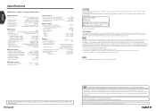
...the dealer or an experienced radio/TV technician for help. This product incorporates copyright protection technology that interference will not occur in a particular installation. Manufactured under license from that to Part 15 of this equipment if an unauthorized change without notice. English Specifications Specifications subject to this ...be determined by turning the equipment off and on , or inside the product relating to laser product safety. English 91 KENWOOD CORPORATION 2967-3, ISHIKAWA-CHO, HACHIOJI-SHI TOKYO, JAPAN KENWOOD CORP. In compliance with Canadian ICES-003.
...the dealer or an experienced radio/TV technician for help. This product incorporates copyright protection technology that interference will not occur in a particular installation. Manufactured under license from that to Part 15 of this equipment if an unauthorized change without notice. English Specifications Specifications subject to this ...be determined by turning the equipment off and on , or inside the product relating to laser product safety. English 91 KENWOOD CORPORATION 2967-3, ISHIKAWA-CHO, HACHIOJI-SHI TOKYO, JAPAN KENWOOD CORP. In compliance with Canadian ICES-003.

Installation Manual
Page 1
KVT-815DVD KVT-745DVD KVT-715DVD MONITOR WITH DVD RECEIVER INSTALLATION MANUAL MONITEUR AVEC RÉCEPTEUR DVD MANUEL D'INSTALLATION MONITOR CON RECEPTOR DVD MANUAL DE INSTALACIÓN MONITOR COM RECEPTOR DVD MANUAL DE INSTALAÇÃO © PRINTED IN JAPAN B54-4433-00/00 (K)(AI)
KVT-815DVD KVT-745DVD KVT-715DVD MONITOR WITH DVD RECEIVER INSTALLATION MANUAL MONITEUR AVEC RÉCEPTEUR DVD MANUEL D'INSTALLATION MONITOR CON RECEPTOR DVD MANUAL DE INSTALACIÓN MONITOR COM RECEPTOR DVD MANUAL DE INSTALAÇÃO © PRINTED IN JAPAN B54-4433-00/00 (K)(AI)
Installation Manual
Page 2
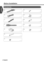
English Before Installation Accessories 1 2 3 4 5 6 7 8 ..........1 9 ..........1 0 ..........1 - ..........1 = ..........1 ..........2 ..........4 ..........4 ..........2 ..........2 ..........4 ..........4 2 English
English Before Installation Accessories 1 2 3 4 5 6 7 8 ..........1 9 ..........1 0 ..........1 - ..........1 = ..........1 ..........2 ..........4 ..........4 ..........2 ..........2 ..........4 ..........4 2 English
Installation Manual
Page 3
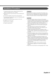
battery. 2. Reconnect the - Install the unit in the following order: ground, battery, ignition. 5. Always connect those wires to the power source running through the fuse box. 2CAUTION • If .... • If the console has a lid, make sure the wires aren't touching to the unit. 6. connector to install the unit so that the mounting angle is installed, check whether the brake lamps, blinkers, wipers, etc. Installation Procedure 1. Connect the speaker wires of the unconnected wires or the terminals. • Connect the speaker wires...
battery. 2. Reconnect the - Install the unit in the following order: ground, battery, ignition. 5. Always connect those wires to the power source running through the fuse box. 2CAUTION • If .... • If the console has a lid, make sure the wires aren't touching to the unit. 6. connector to install the unit so that the mounting angle is installed, check whether the brake lamps, blinkers, wipers, etc. Installation Procedure 1. Connect the speaker wires of the unconnected wires or the terminals. • Connect the speaker wires...
Installation Manual
Page 7
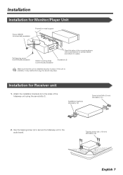
...to the sides of the mounting sleeve with a screwdriver or similar utensil and attach it may malfunction (eg, the sound may skip). Installation Installation for Receiver unit 1. Installation for Monitor/Player Unit Screw (M4X8) (commercially available) Firewall or metal support Self-tapping screw (commercially available) Bend the tabs of the... bolts 7. Metal mounting strap (commercially available) Accessory 5 Make sure that the unit is unstable, it in place. If the unit is installed securely in place. Tapping screw (ø4 × 16 mm) (Accessory 8) English 7
...to the sides of the mounting sleeve with a screwdriver or similar utensil and attach it may malfunction (eg, the sound may skip). Installation Installation for Receiver unit 1. Installation for Monitor/Player Unit Screw (M4X8) (commercially available) Firewall or metal support Self-tapping screw (commercially available) Bend the tabs of the... bolts 7. Metal mounting strap (commercially available) Accessory 5 Make sure that the unit is unstable, it in place. If the unit is installed securely in place. Tapping screw (ø4 × 16 mm) (Accessory 8) English 7

Installation Manual
Page 8
or = Bracket Screws (included in audio unit package) 8 English or = Screws (included in audio unit package) Audio unit or others Accessory - English Installation Installing in Japanese-Made Cars ■ Installing on Toyota, Nissan or Mitsubishi Car Using Brackets at Holes shown by "¶" or Accessory -
or = Bracket Screws (included in audio unit package) 8 English or = Screws (included in audio unit package) Audio unit or others Accessory - English Installation Installing in Japanese-Made Cars ■ Installing on Toyota, Nissan or Mitsubishi Car Using Brackets at Holes shown by "¶" or Accessory -

Installation Manual
Page 9
... two holes of accessory 0 to fix the bracket. Accessory - Bracket Screws (included in audio unit package) English 9 Bend each accessory tab into the hole of installation bracket to fix the bracket. Use a flat-blade screwdriver or pliers, and bend each end of the right and left unit sides. Mount the bracket... at both sides as shown below. 1. Accessory 0 Audio unit or others 2. ■ Installation on Toyota Car using Brackets at Holes shown by "¶" or When using accessories 0 as shown.
... two holes of accessory 0 to fix the bracket. Accessory - Bracket Screws (included in audio unit package) English 9 Bend each accessory tab into the hole of installation bracket to fix the bracket. Use a flat-blade screwdriver or pliers, and bend each end of the right and left unit sides. Mount the bracket... at both sides as shown below. 1. Accessory 0 Audio unit or others 2. ■ Installation on Toyota Car using Brackets at Holes shown by "¶" or When using accessories 0 as shown.
Installation Manual
Page 10
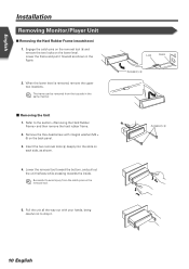
...; Removing the Unit 1. Remove the Hex-head screw with your hands, being careful not to the section and then remove the hard rubber frame. 2. English Installation Removing Monitor/Player Unit ■ Removing the Hard Rubber Frame (escutcheon) 1.
...; Removing the Unit 1. Remove the Hex-head screw with your hands, being careful not to the section and then remove the hard rubber frame. 2. English Installation Removing Monitor/Player Unit ■ Removing the Hard Rubber Frame (escutcheon) 1.


