
Instruction Manual
Page 3
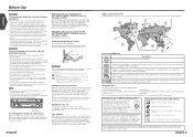
...8226; Do not use of improper screws might result in damage to "N" position if provided.) Navigation units you can control from the KVT-815DVD/745DVD/715DVD Receiver (in November of 2003): KNA-DV2100, KNA-DV3100 Loading and Replacing the battery Use one with each control screen ... in the icon indicates the number of voice languages. (Max. 8 languages) 32 Number of the unit falls such as during installation, consult your Kenwood dealer. Unplayable discs This player cannot play . If that the unit is moving. Reset button Screen brightness during low temperatures When ...
...8226; Do not use of improper screws might result in damage to "N" position if provided.) Navigation units you can control from the KVT-815DVD/745DVD/715DVD Receiver (in November of 2003): KNA-DV2100, KNA-DV3100 Loading and Replacing the battery Use one with each control screen ... in the icon indicates the number of voice languages. (Max. 8 languages) 32 Number of the unit falls such as during installation, consult your Kenwood dealer. Unplayable discs This player cannot play . If that the unit is moving. Reset button Screen brightness during low temperatures When ...
Instruction Manual
Page 46
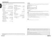
...SHI TOKYO, JAPAN KENWOOD CORP. CERTIFIES THIS EQUIPMENT CONFORMS TO DHHS REGULATIONS N0.21 CFR 1040. 10, CHAPTER 1, SUBCHAPTER J. Location : Bottom Panel FCC WARNING This equipment may cause harmful interference to radio communications, if it is not installed and used in a particular installation. Use of Dolby...try to correct the interference by one or more , 0.01% of pixels may not light or may result in a residential installation. The user could lose the authority to operate this equipment may cause harmful interference unless the modifications are expressly approved in the ...
...SHI TOKYO, JAPAN KENWOOD CORP. CERTIFIES THIS EQUIPMENT CONFORMS TO DHHS REGULATIONS N0.21 CFR 1040. 10, CHAPTER 1, SUBCHAPTER J. Location : Bottom Panel FCC WARNING This equipment may cause harmful interference to radio communications, if it is not installed and used in a particular installation. Use of Dolby...try to correct the interference by one or more , 0.01% of pixels may not light or may result in a residential installation. The user could lose the authority to operate this equipment may cause harmful interference unless the modifications are expressly approved in the ...

Installation Manual
Page 1
KVT-815DVD KVT-745DVD KVT-715DVD MONITOR WITH DVD RECEIVER INSTALLATION MANUAL MONITEUR AVEC RÉCEPTEUR DVD MANUEL D'INSTALLATION MONITOR CON RECEPTOR DVD MANUAL DE INSTALACIÓN MONITOR COM RECEPTOR DVD MANUAL DE INSTALAÇÃO © PRINTED IN JAPAN B54-4433-00/00 (K)(AI)
KVT-815DVD KVT-745DVD KVT-715DVD MONITOR WITH DVD RECEIVER INSTALLATION MANUAL MONITEUR AVEC RÉCEPTEUR DVD MANUEL D'INSTALLATION MONITOR CON RECEPTOR DVD MANUAL DE INSTALACIÓN MONITOR COM RECEPTOR DVD MANUAL DE INSTALAÇÃO © PRINTED IN JAPAN B54-4433-00/00 (K)(AI)
Installation Manual
Page 2
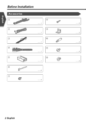
English Before Installation Accessories 1 2 3 4 5 6 7 8 ..........1 9 ..........1 0 ..........1 - ..........1 = ..........1 ..........2 ..........4 ..........4 ..........2 ..........2 ..........4 ..........4 2 English
English Before Installation Accessories 1 2 3 4 5 6 7 8 ..........1 9 ..........1 0 ..........1 - ..........1 = ..........1 ..........2 ..........4 ..........4 ..........2 ..........2 ..........4 ..........4 2 English
Installation Manual
Page 3
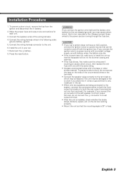
...terminals. • Connect the speaker wires correctly to the terminals to a rear output terminal. • After the unit is 30° or less. Install the unit in the following order: ground, battery, ignition. 5. To prevent a short circuit, do not remove the caps on the car are being...8226; If the fuse blows, first make sure the wires aren't touching to both the rear output terminals (do not connect the - battery. 8. Installation Procedure 1. Make the proper input and output wire connections for each unit. 3. Connect the wiring harness wires in your car's ignition does not have...
...terminals. • Connect the speaker wires correctly to the terminals to a rear output terminal. • After the unit is 30° or less. Install the unit in the following order: ground, battery, ignition. 5. To prevent a short circuit, do not remove the caps on the car are being...8226; If the fuse blows, first make sure the wires aren't touching to both the rear output terminals (do not connect the - battery. 8. Installation Procedure 1. Make the proper input and output wire connections for each unit. 3. Connect the wiring harness wires in your car's ignition does not have...
Installation Manual
Page 7
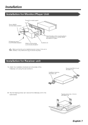
...support Self-tapping screw (commercially available) Bend the tabs of the hideaway unit using the sems bolts 7. If the unit is installed securely in place. Use the tapping screw 8 to secure the hideaway unit to the sides of the mounting sleeve with a... screwdriver or similar utensil and attach it may malfunction (eg, the sound may skip). Attach the installation brackets 9 to the audio board. Tapping screw (ø4 × 16 mm) (Accessory 8) English 7 Installation brackets (Accessory 9) Sems bolts (M4 × 8 mm) (Accessory 7) 2. Metal mounting strap (commercially...
...support Self-tapping screw (commercially available) Bend the tabs of the hideaway unit using the sems bolts 7. If the unit is installed securely in place. Use the tapping screw 8 to secure the hideaway unit to the sides of the mounting sleeve with a... screwdriver or similar utensil and attach it may malfunction (eg, the sound may skip). Attach the installation brackets 9 to the audio board. Tapping screw (ø4 × 16 mm) (Accessory 8) English 7 Installation brackets (Accessory 9) Sems bolts (M4 × 8 mm) (Accessory 7) 2. Metal mounting strap (commercially...

Installation Manual
Page 8
or = Bracket Screws (included in audio unit package) 8 English or = Screws (included in audio unit package) Audio unit or others Accessory - English Installation Installing in Japanese-Made Cars ■ Installing on Toyota, Nissan or Mitsubishi Car Using Brackets at Holes shown by "¶" or Accessory -
or = Bracket Screws (included in audio unit package) 8 English or = Screws (included in audio unit package) Audio unit or others Accessory - English Installation Installing in Japanese-Made Cars ■ Installing on Toyota, Nissan or Mitsubishi Car Using Brackets at Holes shown by "¶" or Accessory -

Installation Manual
Page 9
Bend each accessory tab into the hole of installation bracket to fix the bracket. Use a flat-blade screwdriver or pliers, and bend each end of the right and left unit sides. Use accessories 0 at ... 0 Accessory Screws (included in audio unit package) 3. Mount the bracket at both sides as shown below. 1. Bracket Screws (included in audio unit package) English 9 ■ Installation on Toyota Car using Brackets at Holes shown by "¶" or When using accessories 0 as shown. If so, tighten the bracket using the bracket shown...
Bend each accessory tab into the hole of installation bracket to fix the bracket. Use a flat-blade screwdriver or pliers, and bend each end of the right and left unit sides. Use accessories 0 at ... 0 Accessory Screws (included in audio unit package) 3. Mount the bracket at both sides as shown below. 1. Bracket Screws (included in audio unit package) English 9 ■ Installation on Toyota Car using Brackets at Holes shown by "¶" or When using accessories 0 as shown. If so, tighten the bracket using the bracket shown...
Installation Manual
Page 10
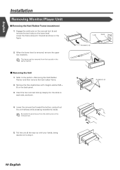
... the unit all the way out with integral washer (M4 × 6) on each side, as shown in the same manner. ˙ Removing the Unit 1. English Installation Removing Monitor/Player Unit ■ Removing the Hard Rubber Frame (escutcheon) 1.
... the unit all the way out with integral washer (M4 × 6) on each side, as shown in the same manner. ˙ Removing the Unit 1. English Installation Removing Monitor/Player Unit ■ Removing the Hard Rubber Frame (escutcheon) 1.


