
Instructions
Page 1
VN-C655 Serial No. which is located on the body. DOME TYPE NETWORK CAMERA VN-C655 READ ME FIRST For Customer Use: Enter below the Serial No. LWT0202-001A-H Retain this information for future reference. Model No.
VN-C655 Serial No. which is located on the body. DOME TYPE NETWORK CAMERA VN-C655 READ ME FIRST For Customer Use: Enter below the Serial No. LWT0202-001A-H Retain this information for future reference. Model No.
Instructions
Page 4
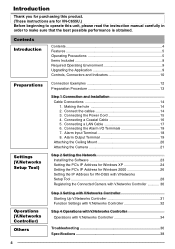
Alarm Output Terminal 19 Attaching the Ceiling Mount 20 Attaching the Camera 21 Step 2 Setting the Network Installing the Software 23 Setting the PC's IP Address for Windows XP 24 Setting the PC's IP Address for Windows 2000 26 Setting the IP Address for VN-C655U.) Before beginning to make sure that the best possible...
Alarm Output Terminal 19 Attaching the Ceiling Mount 20 Attaching the Camera 21 Step 2 Setting the Network Installing the Software 23 Setting the PC's IP Address for Windows XP 24 Setting the PC's IP Address for Windows 2000 26 Setting the IP Address for VN-C655U.) Before beginning to make sure that the best possible...

Instructions
Page 5
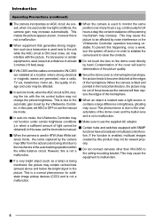
... it in an upside down position on the network Ⅵ Optical + Electronic zooming without decreasing the frame rate. function or a noticeable shortening of its base uppermost. ample in bright- at a strong light source, for VN-C655. When the camera target area contains an area The camera is also compatible with IR illumination that have...
... it in an upside down position on the network Ⅵ Optical + Electronic zooming without decreasing the frame rate. function or a noticeable shortening of its base uppermost. ample in bright- at a strong light source, for VN-C655. When the camera target area contains an area The camera is also compatible with IR illumination that have...
Instructions
Page 6
...malfunction. Ⅵ If a very bright object (such as a transceiver is used in brightness, ghosting ler. If a transceiver or similar V.Networks Controller operation becoming unstable. tion. change the picture brightness. In this case, set the iris mode to clean the contacts. may increase ...difference in ATW (Auto White bal- This is not a malfunction. 6 As a re- Ⅵ When the camera is not a malfunction. Ⅵ Do not connect cameras other than VN-C655 to monitor the same sult, when it at a distance of at the edges TV set, transformer, motor etc...
...malfunction. Ⅵ If a very bright object (such as a transceiver is used in brightness, ghosting ler. If a transceiver or similar V.Networks Controller operation becoming unstable. tion. change the picture brightness. In this case, set the iris mode to clean the contacts. may increase ...difference in ATW (Auto White bal- This is not a malfunction. 6 As a re- Ⅵ When the camera is not a malfunction. Ⅵ Do not connect cameras other than VN-C655 to monitor the same sult, when it at a distance of at the edges TV set, transformer, motor etc...

Instructions
Page 12
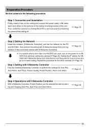
Cross Cable PC 12 Preparations Connection Examples LAN Connection VN-C655 VN-C655 Network Connection VN-C655 LAN PC VN-C655 LAN INTERNET FTP Server PC Peer-to-Peer Connection VN-C655 Images are automatically PC updated at a regular interval.
Cross Cable PC 12 Preparations Connection Examples LAN Connection VN-C655 VN-C655 Network Connection VN-C655 LAN PC VN-C655 LAN INTERNET FTP Server PC Peer-to-Peer Connection VN-C655 Images are automatically PC updated at a regular interval.
Instructions
Page 13
...a hole on to a Ceiling Mount Fix a wire securely for preventing the camera from falling off. ☞ Page 14 Step 2 Setting the Network Install the software [V.Networks Controller], and set the network for VN- C655 first and then setting the camera (☞Page 28, Setting the IP Adress for the PC and... VN-C655. Only then turn on the power for a second one VN-C655 are used, turn on...
...a hole on to a Ceiling Mount Fix a wire securely for preventing the camera from falling off. ☞ Page 14 Step 2 Setting the Network Install the software [V.Networks Controller], and set the network for VN- C655 first and then setting the camera (☞Page 28, Setting the IP Adress for the PC and... VN-C655. Only then turn on the power for a second one VN-C655 are used, turn on...
Instructions
Page 15
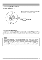
... on again for some time (at the same time. For a system with V.Networks Setup tool). Proper access cannot be established due to IP address redundancy if the power is set to VN-C655. 15 3 Connecting the Power Cord Connect the camera to the DC 18 V input terminal on the terminal stand. Note The... IP address of VN-C655 is turned on for multiple cameras at one VN-C655 are used, turn on the power for a second one VN-C655 exists on the power for the other cameras. Or turn off the power once for all network equipment and turn on a single LAN environment and...
... on again for some time (at the same time. For a system with V.Networks Setup tool). Proper access cannot be established due to IP address redundancy if the power is set to VN-C655. 15 3 Connecting the Power Cord Connect the camera to the DC 18 V input terminal on the terminal stand. Note The... IP address of VN-C655 is turned on for multiple cameras at one VN-C655 are used, turn on the power for a second one VN-C655 exists on the power for the other cameras. Or turn off the power once for all network equipment and turn on a single LAN environment and...

Instructions
Page 18
...Due to the equipment with a sensor, infrared, door or metallic, or a manual switch. Preparations (Step 1 Connection and Installation) Cable Connections (continued) 6. VN-C655 DC18V R Terminal 1 or 2 OUT 18V 0.6mA Sensor Connection Example 1 VCC R Input Requirements • No-voltage relay input or NPN open collector... The polarity of the input detection can be selected via software. Connecting the Alarm I/O Terminals Connect to external noise, the camera may not work properly even if the length of each cable by loosening the screws on the side to fasten the connectors....
...Due to the equipment with a sensor, infrared, door or metallic, or a manual switch. Preparations (Step 1 Connection and Installation) Cable Connections (continued) 6. VN-C655 DC18V R Terminal 1 or 2 OUT 18V 0.6mA Sensor Connection Example 1 VCC R Input Requirements • No-voltage relay input or NPN open collector... The polarity of the input detection can be selected via software. Connecting the Alarm I/O Terminals Connect to external noise, the camera may not work properly even if the length of each cable by loosening the screws on the side to fasten the connectors....
Instructions
Page 19
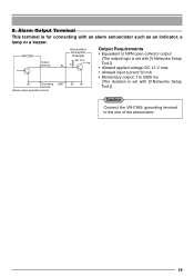
VN-C655 Output terminal Annunciator Connection Example DC 12 V IN R Grounding terminal (Alarm output equivalent circuit) GND Output Requirements • Equivalent to NPN open collector output (The output logic is set with [V.Networks Setup Tool.]) • Allowed applied voltage: DC 12 V max. • Allowed ...input current: 50 mA • Momentary output: 1 to 5000 ms (The duration is for connecting with [V.Networks Setup Tool.]) Caution Connect the VN-C655 grounding terminal to the one of the annunciator. 19 Alarm Output Terminal This terminal is set with an alarm ...
VN-C655 Output terminal Annunciator Connection Example DC 12 V IN R Grounding terminal (Alarm output equivalent circuit) GND Output Requirements • Equivalent to NPN open collector output (The output logic is set with [V.Networks Setup Tool.]) • Allowed applied voltage: DC 12 V max. • Allowed ...input current: 50 mA • Momentary output: 1 to 5000 ms (The duration is for connecting with [V.Networks Setup Tool.]) Caution Connect the VN-C655 grounding terminal to the one of the annunciator. 19 Alarm Output Terminal This terminal is set with an alarm ...
Instructions
Page 23
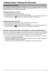
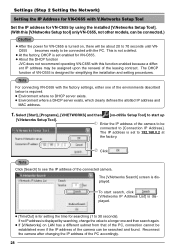
...JVC] folder. 2. Settings (Step 2 Setting the Network) Installing the Software For operating VN-C655, install the software ~fr~o~m~~t~h~e~~C~D~-~R~O~~M~, which is supplied with DirectX9.x or Windows Media Player9.x. If the installation is successfully executed, the [V.Networks] icon is created in [Programs] of the Windows [Start] menu. [vn-c655u...[JVC] folder and then the "setup" folder inside. Operation of the Mpeg4d Decoder DMO. 2. In command prompt, type "regsvr32.exe mp4sds32.ax" and press "Enter" to delete the registration of V.Networks Controller with the camera in [V.Networks...
...JVC] folder. 2. Settings (Step 2 Setting the Network) Installing the Software For operating VN-C655, install the software ~fr~o~m~~t~h~e~~C~D~-~R~O~~M~, which is supplied with DirectX9.x or Windows Media Player9.x. If the installation is successfully executed, the [V.Networks] icon is created in [Programs] of the Windows [Start] menu. [vn-c655u...[JVC] folder and then the "setup" folder inside. Operation of the Mpeg4d Decoder DMO. 2. In command prompt, type "regsvr32.exe mp4sds32.ax" and press "Enter" to delete the registration of V.Networks Controller with the camera in [V.Networks...
Instructions
Page 24
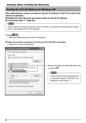
...Setting the PC's IP Address]. 1. Select the network connected to select [Properties]. With Windows XP, follow the procedure below to set the IP address of the PC by which the camera is operated. • Right-click to the PC by which VN-C655 is operated. Note If either [Client for... Microsoft Networks] or [Internet Protocol (TCP/IP)] is selected . Click . • Right-click [...
...Setting the PC's IP Address]. 1. Select the network connected to select [Properties]. With Windows XP, follow the procedure below to set the IP address of the PC by which the camera is operated. • Right-click to the PC by which VN-C655 is operated. Note If either [Client for... Microsoft Networks] or [Internet Protocol (TCP/IP)] is selected . Click . • Right-click [...
Instructions
Page 28
...IP address of the connected camera. Select [Start], [Programs], [V.NETWORKS] and then [vn-c655u Setup Tool] to [Connection IP Address]. Enter the IP address of the camera to be connected to start search, click . [V.Networks IP Address List] is dis- To start up [V.Networks Setup Tool]. Note Click ... upon the renewal of the leasing contract. The IP address is set enabled for VN-C655. ● About the DHCP function JVC does not recommend operating VN-C655 with this [V.Networks Setup tool] only VN-C655, not other models, can be searched and found. played. ● [TimeOut...
...IP address of the connected camera. Select [Start], [Programs], [V.NETWORKS] and then [vn-c655u Setup Tool] to [Connection IP Address]. Enter the IP address of the camera to be connected to start search, click . [V.Networks IP Address List] is dis- To start up [V.Networks Setup Tool]. Note Click ... upon the renewal of the leasing contract. The IP address is set enabled for VN-C655. ● About the DHCP function JVC does not recommend operating VN-C655 with this [V.Networks Setup tool] only VN-C655, not other models, can be searched and found. played. ● [TimeOut...
Instructions
Page 29
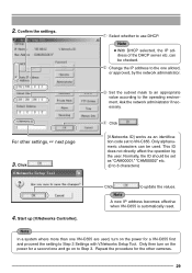
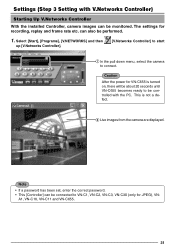
...go on to 8 characters) 4. For other cameras. 29 Click . [V.Networks ID] works as "CAM00001," "CAM00002" etc. (0 to Step 3. Normally, the ID should be used , turn on the power for a VN-C655 first and proceed the setting to VN-C655. Start up [V.Networks Controller]. Only then turn on the power for...or approved, by the user. This ID does not directly affect the operation by the network administrator. Change the IP address to update the values. Note A new IP address becomes effective when VN-C655 is automatically reset. Note ● With DHCP selected, the IP ad- Confirm the...
...go on to 8 characters) 4. For other cameras. 29 Click . [V.Networks ID] works as "CAM00001," "CAM00002" etc. (0 to Step 3. Normally, the ID should be used , turn on the power for a VN-C655 first and proceed the setting to VN-C655. Start up [V.Networks Controller]. Only then turn on the power for...or approved, by the user. This ID does not directly affect the operation by the network administrator. Change the IP address to update the values. Note A new IP address becomes effective when VN-C655 is automatically reset. Note ● With DHCP selected, the IP ad- Confirm the...

Instructions
Page 30
... of 30 fps may not be possible for narrow bandwidth networks. ● Maximum data transmission capacity is 8 Mb/s. When sending out images to VN-C655. Settings (Step 2 Setting the Network) Registering the Connected Camera with V.Networks Controller The connected camera can be registered with a resolution of 640 x 480 can...depending on the image size. ● When in 2 are divided into IP fragments when set to VN-C655, exists. 30 2 Enter [V.Network Name], a name under which the camera is not possible. High Speed: Images will send requests for 640 x 480 images is registered. When...
... of 30 fps may not be possible for narrow bandwidth networks. ● Maximum data transmission capacity is 8 Mb/s. When sending out images to VN-C655. Settings (Step 2 Setting the Network) Registering the Connected Camera with V.Networks Controller The connected camera can be registered with a resolution of 640 x 480 can...depending on the image size. ● When in 2 are divided into IP fragments when set to VN-C655, exists. 30 2 Enter [V.Network Name], a name under which the camera is not possible. High Speed: Images will send requests for 640 x 480 images is registered. When...
Instructions
Page 31
...2 Live images from the camera are displayed. Select [Start], [Programs], [V.NETWORKS] and then up [V.Networks Controller]. [V.Networks Controller] to start 1 In the pull down menu, select the camera to VN-C1, VN-C2, VN-C3, VN-C30 (only for JPEG), VN- A1, VN-C10, VN-C11 and VN-C655. 31 Caution After ...connected to connect. This is turned on, there will be about 20 seconds until VN-C655 becomes ready to be controlled with V.Networks Controller) Starting Up V.Networks Controller With the installed Controller, camera images can be performed. 1. Note • If a password has been set...
...2 Live images from the camera are displayed. Select [Start], [Programs], [V.NETWORKS] and then up [V.Networks Controller]. [V.Networks Controller] to start 1 In the pull down menu, select the camera to VN-C1, VN-C2, VN-C3, VN-C30 (only for JPEG), VN- A1, VN-C10, VN-C11 and VN-C655. 31 Caution After ...connected to connect. This is turned on, there will be about 20 seconds until VN-C655 becomes ready to be controlled with V.Networks Controller) Starting Up V.Networks Controller With the installed Controller, camera images can be performed. 1. Note • If a password has been set...
Instructions
Page 36
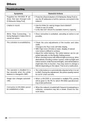
...to see if it takes time to change a little bit depending on the Quality Setting screen. • When shooting scenes with [V.Networks Setup Tool]. During the adjustment, the picture quality cannot be set to see the IP addresses of the monitor and video cards. ...memory capacity. • Once connection is activated, canceling an action is not possible. • Check the color adjustments of all the cameras connected to VN-C655 cannot be adjusted manually on the object. when alternatively shooting outdoor scenes under sunlight and indoor scenes under fluorescent light), auto white ...
...to see if it takes time to change a little bit depending on the Quality Setting screen. • When shooting scenes with [V.Networks Setup Tool]. During the adjustment, the picture quality cannot be set to see the IP addresses of the monitor and video cards. ...memory capacity. • Once connection is activated, canceling an action is not possible. • Check the color adjustments of all the cameras connected to VN-C655 cannot be adjusted manually on the object. when alternatively shooting outdoor scenes under sunlight and indoor scenes under fluorescent light), auto white ...

Instructions
Page 40
R is a registered trademark in Thailand LWT0202-001A-H VN-C655 DOME TYPE NETWORK CAMERA and many other countries. © 2004 Victor Company of Japan, Limited. Printed in Japan, the U.S.A., the U.K. R is a registered trademark owned by Victor Company of Japan, Limited.
R is a registered trademark in Thailand LWT0202-001A-H VN-C655 DOME TYPE NETWORK CAMERA and many other countries. © 2004 Victor Company of Japan, Limited. Printed in Japan, the U.S.A., the U.K. R is a registered trademark owned by Victor Company of Japan, Limited.
