Instructions
Page 2
... servicing to repair it yourself or remove the rear cover. Do not allow objects or liquid into the cabinet openings. 5. No user serviceable parts inside. CAUTION: TO INSURE PERSONAL SAFETY, OBSERVE THE FOLLOWING RULES REGARDING THE USE OF THIS UNIT. 1. In the event of electric shock. Changes or modifications not approved by JVC could void the warranty. * When you don't use this TV set...
... servicing to repair it yourself or remove the rear cover. Do not allow objects or liquid into the cabinet openings. 5. No user serviceable parts inside. CAUTION: TO INSURE PERSONAL SAFETY, OBSERVE THE FOLLOWING RULES REGARDING THE USE OF THIS UNIT. 1. In the event of electric shock. Changes or modifications not approved by JVC could void the warranty. * When you don't use this TV set...
Instructions
Page 5
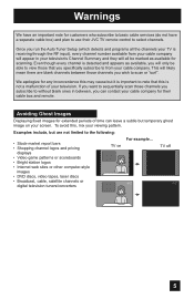
... have a separate cable box) and plan to use their cable box and remote. Even though every channel is receiving through the RF input), every channel number available from your cable company for customers who subscribe to basic cable services (do not have an important note for their JVC TV remote control to the following: • Stock-market report bars • Shopping channel logos and pricing displays • Video game patterns or scoreboards •...
... have a separate cable box) and plan to use their cable box and remote. Even though every channel is receiving through the RF input), every channel number available from your cable company for customers who subscribe to basic cable services (do not have an important note for their JVC TV remote control to the following: • Stock-market report bars • Shopping channel logos and pricing displays • Video game patterns or scoreboards •...
Instructions
Page 10
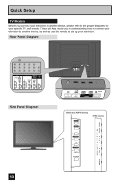
... Panel Diagram POWER 10 INPUT 3 S-VIDEO Y VIDEO PB L PR R INPUT 4 INPUT 5 / INPUT 1 AUDIO AUDIO OUT Y VIDEO VIDEO PB L L L PR R R R 75 Ω (VHF/UHF) PHOTO VIEWER INPUT 1 SERVICE INPUT 2 DIGITAL AUDIO OPTICAL OUT 75 Ω (VHF/UHF) PHOTO VIEWER INPUT 1 SERVICE INPUT 2 DIGITAL AUDIO OPTICAL OUT X688 and XM48 series INPUT X788 series MENU INPUT MENU C H CHANNEL OK VOLUME BACK POWER VOL OK BACK POWER These will help assist you connect your television to another device, as well as use the remote to the proper diagrams for your television. Quick Setup TV...
... Panel Diagram POWER 10 INPUT 3 S-VIDEO Y VIDEO PB L PR R INPUT 4 INPUT 5 / INPUT 1 AUDIO AUDIO OUT Y VIDEO VIDEO PB L L L PR R R R 75 Ω (VHF/UHF) PHOTO VIEWER INPUT 1 SERVICE INPUT 2 DIGITAL AUDIO OPTICAL OUT 75 Ω (VHF/UHF) PHOTO VIEWER INPUT 1 SERVICE INPUT 2 DIGITAL AUDIO OPTICAL OUT X688 and XM48 series INPUT X788 series MENU INPUT MENU C H CHANNEL OK VOLUME BACK POWER VOL OK BACK POWER These will help assist you connect your television to another device, as well as use the remote to the proper diagrams for your television. Quick Setup TV...
Instructions
Page 14
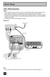
... switching the cables. • You may vary colors. Diagram #1 R LV IN OUT VCR IN OUT Cable or Antenna Output OR Coaxial Cable AUDIO AUDIO AUDIO COMPONENT AUDIO COMPONENT INPUT 3 S-VIDEO Y VIDEO PB L PR R INPUT 4 INPUT 5 / INPUT 1 AUDIO AUDIO OUT Y VIDEO VIDEO PB L L L PR R R R 75 Ω (VHF/UHF) PHOTO VIEWER INPUT 1 SERVICE INPUT 2 DIGITAL AUDIO OPTICAL OUT TV Rear Panel Green Blue Red Y PB PR OUT AUDIO OUT R L DVD Player Note: • If this connection setup does not work for more information. • Be careful not to Input 1. Some models...
... switching the cables. • You may vary colors. Diagram #1 R LV IN OUT VCR IN OUT Cable or Antenna Output OR Coaxial Cable AUDIO AUDIO AUDIO COMPONENT AUDIO COMPONENT INPUT 3 S-VIDEO Y VIDEO PB L PR R INPUT 4 INPUT 5 / INPUT 1 AUDIO AUDIO OUT Y VIDEO VIDEO PB L L L PR R R R 75 Ω (VHF/UHF) PHOTO VIEWER INPUT 1 SERVICE INPUT 2 DIGITAL AUDIO OPTICAL OUT TV Rear Panel Green Blue Red Y PB PR OUT AUDIO OUT R L DVD Player Note: • If this connection setup does not work for more information. • Be careful not to Input 1. Some models...
Instructions
Page 18
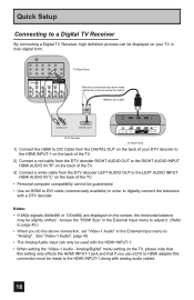
... External Input menu to "Analog". Analog/Digital" menu setting on the screen, the horizontal balance may be slightly shifted. Quick Setup Connecting to a Digital TV Receiver By connecting a Digital TV Receiver, high definition pictures can only be used with the HDMI INPUT-1. • When setting the "Video-1 Audio - AUDIO AUDIO AUDIO COMPONENT AUDIO COMPONENT INPUT 3 S-VIDEO Y VIDEO PB L PR R INPUT 4 INPUT 5 / INPUT 1 AUDIO AUDIO OUT Y VIDEO VIDEO PB L L L PR R R R TV Rear Panel After the connections have been made to the HDMI INPUT-1 along with analog audio cables...
... External Input menu to "Analog". Analog/Digital" menu setting on the screen, the horizontal balance may be slightly shifted. Quick Setup Connecting to a Digital TV Receiver By connecting a Digital TV Receiver, high definition pictures can only be used with the HDMI INPUT-1. • When setting the "Video-1 Audio - AUDIO AUDIO AUDIO COMPONENT AUDIO COMPONENT INPUT 3 S-VIDEO Y VIDEO PB L PR R INPUT 4 INPUT 5 / INPUT 1 AUDIO AUDIO OUT Y VIDEO VIDEO PB L L L PR R R R TV Rear Panel After the connections have been made to the HDMI INPUT-1 along with analog audio cables...
Instructions
Page 19
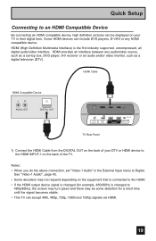
... changed (for a short time until the signal becomes stable. • This TV can include DVD players, D-VHS or any audio/video source, such as a digital television (DTV). HDMI provides an interface between any HDMI compatible device. Notes: • When you do the above connection, set -top box, DVD player, A/V receiver or an audio and/or video monitor, such as a set "Video-1 Audio" in their digital form. HDMI Cable HDMI Compatible Device LR AUDIO OUT DIGITAL OUT 75 Ω (VHF/UHF) PHOTO VIEWER INPUT 1 SERVICE INPUT 2 DIGITAL AUDIO OPTICAL OUT TV Rear Panel 1) Connect...
... changed (for a short time until the signal becomes stable. • This TV can include DVD players, D-VHS or any audio/video source, such as a digital television (DTV). HDMI provides an interface between any HDMI compatible device. Notes: • When you do the above connection, set -top box, DVD player, A/V receiver or an audio and/or video monitor, such as a set "Video-1 Audio" in their digital form. HDMI Cable HDMI Compatible Device LR AUDIO OUT DIGITAL OUT 75 Ω (VHF/UHF) PHOTO VIEWER INPUT 1 SERVICE INPUT 2 DIGITAL AUDIO OPTICAL OUT TV Rear Panel 1) Connect...
Instructions
Page 20
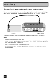
... output sound from your Optical Output connection if the audio source is output can connect an amplifier that is from underneath the television to the back of the amplifier. Notes: • This terminal can only output digital audio. • In order to an amplifier using your optical output You can be PCM or DOLBY DIGITAL. 75 Ω (VHF/UHF) PHOTO VIEWER INPUT 1 SERVICE INPUT 2 DIGITAL AUDIO OPTICAL OUT Amplifier TV Rear Panel 1) Connect the optical cable from your owners manual on Optical...
... output sound from your Optical Output connection if the audio source is output can connect an amplifier that is from underneath the television to the back of the amplifier. Notes: • This terminal can only output digital audio. • In order to an amplifier using your optical output You can be PCM or DOLBY DIGITAL. 75 Ω (VHF/UHF) PHOTO VIEWER INPUT 1 SERVICE INPUT 2 DIGITAL AUDIO OPTICAL OUT Amplifier TV Rear Panel 1) Connect the optical cable from your owners manual on Optical...
Instructions
Page 21
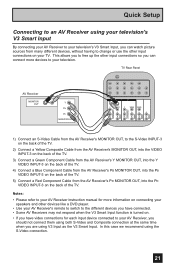
... the TV. 4) Connect a Blue Component Cable from the AV Receiver's PB MONITOR OUT, into the PB VIDEO INPUT-3 on the back of the TV. 5) Connect a Red Component Cable from the AV Receiver's PR MONITOR OUT, into the PR VIDEO INPUT-3 on the back of the TV. This allows you to free up the other input connections on your television. TV Rear Panel AV Receiver MONITOR OUT Y PB PR MONITOR OUT INPUT 3 S-VIDEO Y VIDEO INPUT 4 Y VIDEO VIDEO PB L PB L L L PR R PR R R R AUDIO AUDIO AUDIO COMPONENT AUDIO COMPONENT 1) Connect an S-Video Cable from the AV Receiver's MONITOR...
... the TV. 4) Connect a Blue Component Cable from the AV Receiver's PB MONITOR OUT, into the PB VIDEO INPUT-3 on the back of the TV. 5) Connect a Red Component Cable from the AV Receiver's PR MONITOR OUT, into the PR VIDEO INPUT-3 on the back of the TV. This allows you to free up the other input connections on your television. TV Rear Panel AV Receiver MONITOR OUT Y PB PR MONITOR OUT INPUT 3 S-VIDEO Y VIDEO INPUT 4 Y VIDEO VIDEO PB L PB L L L PR R PR R R R AUDIO AUDIO AUDIO COMPONENT AUDIO COMPONENT 1) Connect an S-Video Cable from the AV Receiver's MONITOR...
Instructions
Page 23
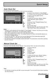
... move to reset the clock after a power interruption. Quick Setup Auto Clock Set You may not be set your clock manually, choose "Manual". Notes: • "Channel" can be selected only when Mode is set to the "Auto Tuner Setup" Plug-in Menu automatically. Auto (Analog) - - 10 : 30 AM Atlantic On Set √® † √® † √® To choose "Auto (Analog)" or "Auto (Digital)" To "Channel" when you selected "Auto (Digital)" To select a receiving digital channel To "Time Zone...
... move to reset the clock after a power interruption. Quick Setup Auto Clock Set You may not be set your clock manually, choose "Manual". Notes: • "Channel" can be selected only when Mode is set to the "Auto Tuner Setup" Plug-in Menu automatically. Auto (Analog) - - 10 : 30 AM Atlantic On Set √® † √® † √® To choose "Auto (Analog)" or "Auto (Digital)" To "Channel" when you selected "Auto (Digital)" To select a receiving digital channel To "Time Zone...
Instructions
Page 27
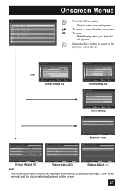
... BACK button to return to the previous menu screen Initial Setup 1/2 Noise Muting Language Front Panel Lock V-Chip Set Lock Code Closed Caption On English Off Select Operate BACK Back MENU Exit Initial Setup 1/2 Initial Setup Auto Shut Off Software Version Power Indicator Optical Out Quick Start-up 2/2 Off High PCM Off Select Operate BACK Back MENU Exit Initial Setup 2/2 - + Tuner Setup Auto Tuner Setup Channel Summary Find Channel Digital Antenna Level Tuner Diagnostic (Service Use Only) Select OK BACK MENU Operate Back Exit Tuner Setup External Input HDMI Size Video...
... BACK button to return to the previous menu screen Initial Setup 1/2 Noise Muting Language Front Panel Lock V-Chip Set Lock Code Closed Caption On English Off Select Operate BACK Back MENU Exit Initial Setup 1/2 Initial Setup Auto Shut Off Software Version Power Indicator Optical Out Quick Start-up 2/2 Off High PCM Off Select Operate BACK Back MENU Exit Initial Setup 2/2 - + Tuner Setup Auto Tuner Setup Channel Summary Find Channel Digital Antenna Level Tuner Diagnostic (Service Use Only) Select OK BACK MENU Operate Back Exit Tuner Setup External Input HDMI Size Video...

Instructions
Page 38
..., Solid or Flashing Text Color, Edge Color, Background Color: Auto, White, Black, Red, Green, Blue, Yellow, Magenta, or Cyan Press the MENU button when finished Closed Caption > Appearance 1/2 Preview Closed Caption Sample Appearance Mode Font Size Font Style Text / Edge Opacity Background Opacity Select Operate Manual Standard Auto Solid Solid BACK Back MENU Exit Closed Caption > Appearance 2/2 Preview Closed Caption Sample Text Color Edge Color Background Color White White Black Select OK BACK MENU Operate Back Exit All fonts are playing a video tape. •...
..., Solid or Flashing Text Color, Edge Color, Background Color: Auto, White, Black, Red, Green, Blue, Yellow, Magenta, or Cyan Press the MENU button when finished Closed Caption > Appearance 1/2 Preview Closed Caption Sample Appearance Mode Font Size Font Style Text / Edge Opacity Background Opacity Select Operate Manual Standard Auto Solid Solid BACK Back MENU Exit Closed Caption > Appearance 2/2 Preview Closed Caption Sample Text Color Edge Color Background Color White White Black Select OK BACK MENU Operate Back Exit All fonts are playing a video tape. •...
Instructions
Page 41
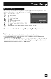
... Back MENU Exit The auto tuner is finished when the message "Programming Over !" If you need to select "Scan Mode" • If no channels were found using Auto Tuner Setup, check your antenna cable and the settings for Tuner Mode/Scan Mode. • You can also access the "Front Menu" screen by using the MENU button on the side of the TV instead of the remote control. Tuner Setup Auto Tuner Setup The auto tuner setup function is described on the side panel and enter by using the CHANNEL buttons...
... Back MENU Exit The auto tuner is finished when the message "Programming Over !" If you need to select "Scan Mode" • If no channels were found using Auto Tuner Setup, check your antenna cable and the settings for Tuner Mode/Scan Mode. • You can also access the "Front Menu" screen by using the MENU button on the side of the TV instead of the remote control. Tuner Setup Auto Tuner Setup The auto tuner setup function is described on the side panel and enter by using the CHANNEL buttons...
Instructions
Page 46
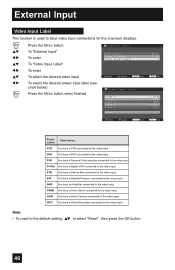
... default setting, π† to label video input connections for the onscreen displays. π† √® π† √® π† √® Press the MENU button To "External Input" To enter To "Video Input Label" To enter To select the desired video input To select the desired preset input label (see chart below) Press the MENU button when finished External Input HDMI Size Video-1 Audio Video Input Label Select Operate Back Back Video Input Label Video-1 Video-2 Video-3 Video-4 Video-5 Reset...
... default setting, π† to label video input connections for the onscreen displays. π† √® π† √® π† √® Press the MENU button To "External Input" To enter To "Video Input Label" To enter To select the desired video input To select the desired preset input label (see chart below) Press the MENU button when finished External Input HDMI Size Video-1 Audio Video Input Label Select Operate Back Back Video Input Label Video-1 Video-2 Video-3 Video-4 Video-5 Reset...
Instructions
Page 55
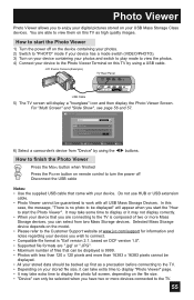
...) TV Rear Panel 75 Ω (VHF/UHF) PHOTO VIEWER INPUT 1 SERVICE INPUT 2 DIGITAL AUDIO OPTICAL OUT USB Cable 5) The TV screen will appear when you have two or more than 16383 x 16383 pixels cannot be displayed. • All your stored data should be backed up first as high quality images. How to finish the Photo Viewer Press the MENU button when finished Press the POWER button on remote control to turn...
...) TV Rear Panel 75 Ω (VHF/UHF) PHOTO VIEWER INPUT 1 SERVICE INPUT 2 DIGITAL AUDIO OPTICAL OUT USB Cable 5) The TV screen will appear when you have two or more than 16383 x 16383 pixels cannot be displayed. • All your stored data should be backed up first as high quality images. How to finish the Photo Viewer Press the MENU button when finished Press the POWER button on remote control to turn...
Instructions
Page 60
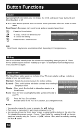
...; buttons. • Each mode is memorized for when you a choice of four TV picture display settings, including a display of your TV. Smart Sound Sound Effect Off Off Select Operate Menu Exit Note: • Smart Sound may become an unnatural effect, depending on the side panel and enter by using the MENU button on the side of the TV instead of the remote control. Video Status The Video Status button gives you are playing video games connected to...
...; buttons. • Each mode is memorized for when you a choice of four TV picture display settings, including a display of your TV. Smart Sound Sound Effect Off Off Select Operate Menu Exit Note: • Smart Sound may become an unnatural effect, depending on the side panel and enter by using the MENU button on the side of the TV instead of the remote control. Video Status The Video Status button gives you are playing video games connected to...
Instructions
Page 67
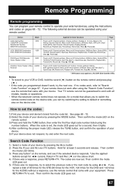
DVD Player, DVD Recorder Home Theater in Box, AUDIO Power on/off, Audio Input Selection (V1 button), Volume up /down , Muting, 72 Receiver DVD operation buttons: Menu on/off , Arrow buttons, OK/Enter, Back, Guide (EPG), 69, 70 TV/VCR, Closed Caption, Eject ( ), Rewind ( ), Playback ( ), Forward ( ), Record ( ), Stop ( ), Pause ( ). If your remote does not work , refer to "Search Code Function" on page 67. How to set the codes 1) Find your device. Then confirm the mode LED on the...
DVD Player, DVD Recorder Home Theater in Box, AUDIO Power on/off, Audio Input Selection (V1 button), Volume up /down , Muting, 72 Receiver DVD operation buttons: Menu on/off , Arrow buttons, OK/Enter, Back, Guide (EPG), 69, 70 TV/VCR, Closed Caption, Eject ( ), Rewind ( ), Playback ( ), Forward ( ), Record ( ), Stop ( ), Pause ( ). If your remote does not work , refer to "Search Code Function" on page 67. How to set the codes 1) Find your device. Then confirm the mode LED on the...
Instructions
Page 74
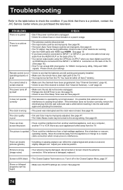
... are working and properly installed. Troubleshooting Refer to the table below to the TV. If you will not be having difficulties. See page 19. • If you have a device connected to INPUT-1 or INPUT-2, you think that external noise or interference is a problem, contact the JVC Service Center where you have been programmed. Remote control is no picture or sound • The antenna could be disconnected. • The input mode...
... are working and properly installed. Troubleshooting Refer to the table below to the TV. If you will not be having difficulties. See page 19. • If you have a device connected to INPUT-1 or INPUT-2, you think that external noise or interference is a problem, contact the JVC Service Center where you have been programmed. Remote control is no picture or sound • The antenna could be disconnected. • The input mode...
Instructions
Page 75
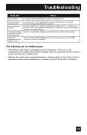
... the CHANNEL- Unless crackling sounds the sound or picture become abnormal, this is not a malfunction. 75 buttons on the side panel of the television changes. The Digital Tuner will be seen on the screen if the power is turned on immediately after it has been turned off, this does not reset it correctly, unplug the power cord and plug it back in. Press the menu button. If there is no problem...
... the CHANNEL- Unless crackling sounds the sound or picture become abnormal, this is not a malfunction. 75 buttons on the side panel of the television changes. The Digital Tuner will be seen on the screen if the power is turned on immediately after it has been turned off, this does not reset it correctly, unplug the power cord and plug it back in. Press the menu button. If there is no problem...
Instructions
Page 76
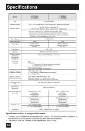
Specifications Model Type Reception Format Reception Range Power Source Power Consumption Screen Size Audio Output Speakers Antenna Terminal (VHF/UHF, ATSC/DIGITAL CABLE IN) Input 3, 4, 5 Terminal Input 3, 4 Terminal (Component Terminal) Input 1, 2 Terminal (HDMI Input Terminal) Audio Output Jacks (FIX) Optical Output Digital Audio Dimensions (inch/cm) W X H X D Weight (lbs / kg) Accessories LT-37X688 LT-37XM48 LT-42X688 LT-42XM48 LCD Flat Television NTSC, BTSC System (Multi-Channel Sound) ATSC Terrestrial, Digital Cable VHF 2 to 13, UHF 14 to 69 at ATSC, CATV 135 Sub, Mid, Super, ...
Specifications Model Type Reception Format Reception Range Power Source Power Consumption Screen Size Audio Output Speakers Antenna Terminal (VHF/UHF, ATSC/DIGITAL CABLE IN) Input 3, 4, 5 Terminal Input 3, 4 Terminal (Component Terminal) Input 1, 2 Terminal (HDMI Input Terminal) Audio Output Jacks (FIX) Optical Output Digital Audio Dimensions (inch/cm) W X H X D Weight (lbs / kg) Accessories LT-37X688 LT-37XM48 LT-42X688 LT-42XM48 LCD Flat Television NTSC, BTSC System (Multi-Channel Sound) ATSC Terrestrial, Digital Cable VHF 2 to 13, UHF 14 to 69 at ATSC, CATV 135 Sub, Mid, Super, ...
Instructions
Page 77
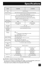
... source software is not recommended for your TV set 's on-screen cable channel numbers) is embedded in this product. Specifications Model LT-42X788 LT-47X788 Type Reception Format Reception Range Power Source Power Consumption Screen Size Audio Output Speakers Antenna Terminal (VHF/UHF, ATSC/DIGITAL CABLE IN) Input 3, 4, 5 Terminal Input 3, 4 Terminal (Component Terminal) Input 1, 2 Terminal (HDMI Input Terminal) Audio Output Jacks (FIX) Optical Output Digital Audio Dimensions (inch/cm) W X H X D Weight (lbs / kg) Accessories LCD Flat Television NTSC, BTSC System (Multi-Channel Sound...
... source software is not recommended for your TV set 's on-screen cable channel numbers) is embedded in this product. Specifications Model LT-42X788 LT-47X788 Type Reception Format Reception Range Power Source Power Consumption Screen Size Audio Output Speakers Antenna Terminal (VHF/UHF, ATSC/DIGITAL CABLE IN) Input 3, 4, 5 Terminal Input 3, 4 Terminal (Component Terminal) Input 1, 2 Terminal (HDMI Input Terminal) Audio Output Jacks (FIX) Optical Output Digital Audio Dimensions (inch/cm) W X H X D Weight (lbs / kg) Accessories LCD Flat Television NTSC, BTSC System (Multi-Channel Sound...


