KY-F75U 52 page instruction manual (3MB)
Page 1
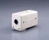
Retain this information for future reference. KY-F75 Serial No. For Customer Use: Enter below the Serial No. This instruction book is located on the unit. Model No. LWT0059-001A Introduction Preparations 3CCD Digital Camera 3CCD Digitale Kamera 3CCD Caméra numérique KY-F75 INSTRUCTIONS BEDIENUNGSANLEITUNG MANUEL D'INSTRUCTIONS Recording Settings Others Illustration with optional lens attachment. which is made from 100% recycled paper.
Retain this information for future reference. KY-F75 Serial No. For Customer Use: Enter below the Serial No. This instruction book is located on the unit. Model No. LWT0059-001A Introduction Preparations 3CCD Digital Camera 3CCD Digitale Kamera 3CCD Caméra numérique KY-F75 INSTRUCTIONS BEDIENUNGSANLEITUNG MANUEL D'INSTRUCTIONS Recording Settings Others Illustration with optional lens attachment. which is made from 100% recycled paper.
KY-F75U 52 page instruction manual (3MB)
Page 6
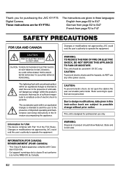
... within the product's enclosure that may be used with 12V DC only. Information for professional use any other power source. NO USER SERVICEABLE PARTS INSIDE. CAUTION: To prevent electric shocks and fire hazards, do not open the cabinet. WARNING: TO REDUCE THE RISK OF ...). Thank you for KY-F75U. These instructions are for purchasing the JVC KY-F75 Digital Camera. This unit should follow National, State and Local Laws. CAUTION: To prevent electric shock, do NOT use only. Refer servicing to persons. This unit is intended to alert the user to the presence of...
... within the product's enclosure that may be used with 12V DC only. Information for professional use any other power source. NO USER SERVICEABLE PARTS INSIDE. CAUTION: To prevent electric shocks and fire hazards, do not open the cabinet. WARNING: TO REDUCE THE RISK OF ...). Thank you for KY-F75U. These instructions are for purchasing the JVC KY-F75 Digital Camera. This unit should follow National, State and Local Laws. CAUTION: To prevent electric shock, do NOT use only. Refer servicing to persons. This unit is intended to alert the user to the presence of...
KY-F75U 52 page instruction manual (3MB)
Page 8
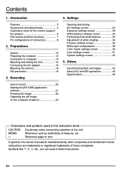
...Specifications 46 How to computer 14 Mounting and setting the lens 15 Connecting the AC adapter 16 Mounting the camera 18 Fall prevention 19 3. E4 Preparations System 10 Preparing the computer 12 Connection to record 20 Starting the [KY-LINK] application software 21 Freezing the image... and mentioned in these instructions are not used in this product 6 Part names and their functions 7 Pin configurations of white shading 34 Process settings screen 35 White spot compensation 38 Color matrix settings screen 39 Lens settings screen 41 System settings screen 42 5. Contents...
...Specifications 46 How to computer 14 Mounting and setting the lens 15 Connecting the AC adapter 16 Mounting the camera 18 Fall prevention 19 3. E4 Preparations System 10 Preparing the computer 12 Connection to record 20 Starting the [KY-LINK] application software 21 Freezing the image... and mentioned in these instructions are not used in this product 6 Part names and their functions 7 Pin configurations of white shading 34 Process settings screen 35 White spot compensation 38 Color matrix settings screen 39 Lens settings screen 41 System settings screen 42 5. Contents...
KY-F75U 52 page instruction manual (3MB)
Page 9
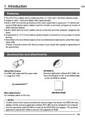
... consult the nearest JVC Service Center or your dealer with 1.45 million effective pixels. ● Output of optical devices. ● Recording in the computer. The exclusive application software [KY-LINK] is a digital camera employing three 1/2" CCD with regards to be shown, the IEEE1394 host adapter and the exclusive application software [KY-LINK] must be installed in the near...
... consult the nearest JVC Service Center or your dealer with 1.45 million effective pixels. ● Output of optical devices. ● Recording in the computer. The exclusive application software [KY-LINK] is a digital camera employing three 1/2" CCD with regards to be shown, the IEEE1394 host adapter and the exclusive application software [KY-LINK] must be installed in the near...
KY-F75U 52 page instruction manual (3MB)
Page 12
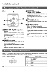
...or flash unit. If the direction of connectors ( ੬ page E9) Mounting and setting the lens ( ੬ page E15) ᕧ [REMOTE] terminal (Metal 10-pin, female) Used to the camera. ᕩ [DC IN] connector (Mini DIN 8-pin, female) Power (DC 12V... this inlet. Introduction (continued) Part names and their functions (continued) [Rear] ᕦ ᕧ ᕨ REMOTE LENS IEEE1394 DC IN POWER SEE INSTRUCTION MANUAL ᕥ ᕩ ᕥ [IEEE1394] digital output connector Digital output connector for the camera is incorrect, the camera may be damaged. Pin configurations of...
...or flash unit. If the direction of connectors ( ੬ page E9) Mounting and setting the lens ( ੬ page E15) ᕧ [REMOTE] terminal (Metal 10-pin, female) Used to the camera. ᕩ [DC IN] connector (Mini DIN 8-pin, female) Power (DC 12V... this inlet. Introduction (continued) Part names and their functions (continued) [Rear] ᕦ ᕧ ᕨ REMOTE LENS IEEE1394 DC IN POWER SEE INSTRUCTION MANUAL ᕥ ᕩ ᕥ [IEEE1394] digital output connector Digital output connector for the camera is incorrect, the camera may be damaged. Pin configurations of...
KY-F75U 52 page instruction manual (3MB)
Page 15
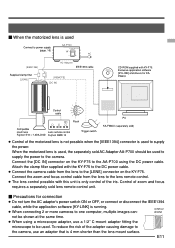
... clamp filter supplied with the KY-F75 to the DC power cable. ● Connect the camera cable from the lens to the lens remote control. ● The lens control possible with this unit is running. ● When connecting 2 or more cameras to one computer, multiple images can- 4 mm or shorter...ON OFF AC [IEEE1394] AC Adapter IEEE1394 cable Supplied clamp filter [LENS] [REMOTE] [DC IN] CD-ROM supplied with KY-F75: Exclusive application software [KY-LINK] and drivers for connection ● Do not turn the AC adapter's power switch ON or OFF, or connect or disconnect the IEEE1394 cable...
... clamp filter supplied with the KY-F75 to the DC power cable. ● Connect the camera cable from the lens to the lens remote control. ● The lens control possible with this unit is running. ● When connecting 2 or more cameras to one computer, multiple images can- 4 mm or shorter...ON OFF AC [IEEE1394] AC Adapter IEEE1394 cable Supplied clamp filter [LENS] [REMOTE] [DC IN] CD-ROM supplied with KY-F75: Exclusive application software [KY-LINK] and drivers for connection ● Do not turn the AC adapter's power switch ON or OFF, or connect or disconnect the IEEE1394 cable...
KY-F75U 52 page instruction manual (3MB)
Page 16
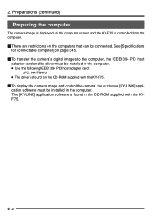
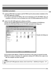
... be installed in the CD-ROM supplied with the KY-F75. Ⅵ To display the camera image and control the camera, the exclusive [KY-LINK] application software must be installed in the computer. ● Use the following IEEE1394 PCI host adapter card: JVC: KA-FW4IU ● The driver is... the computer The camera image is displayed on the computer screen and the KY-F75 is found in the computer. See [Specifications for connectable computer] on page E45. Ⅵ To transfer the camera's digital images to the computer, the IEEE1394 PCI host adapter card and its driver must be connected....
... be installed in the CD-ROM supplied with the KY-F75. Ⅵ To display the camera image and control the camera, the exclusive [KY-LINK] application software must be installed in the computer. ● Use the following IEEE1394 PCI host adapter card: JVC: KA-FW4IU ● The driver is... the computer The camera image is displayed on the computer screen and the KY-F75 is found in the computer. See [Specifications for connectable computer] on page E45. Ⅵ To transfer the camera's digital images to the computer, the IEEE1394 PCI host adapter card and its driver must be connected....
KY-F75U 52 page instruction manual (3MB)
Page 17
.../Remove Programs Ǟ KYLINK. E13 Follow the instructions on the CD-ROM, and double-click Setup.exe. Also, for the KA-FW4IU. Install the IEEE1394 host adapter card KA-FW4IU and the drivers before installation of the driver, see the Readme file on the CD-ROM supplied with the KY-F75 into the computer's CD-ROM drive...
.../Remove Programs Ǟ KYLINK. E13 Follow the instructions on the CD-ROM, and double-click Setup.exe. Also, for the KA-FW4IU. Install the IEEE1394 host adapter card KA-FW4IU and the drivers before installation of the driver, see the Readme file on the CD-ROM supplied with the KY-F75 into the computer's CD-ROM drive...
KY-F75U 52 page instruction manual (3MB)
Page 19
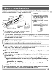
...front of the lens control cable to adjust its position, and then retighten the mount clamp ring. 3. Make settings on the setting screen of the KY-F75. To avoid damaging the camera, make sure that dust do not enter inside the mount. 2. Lock (female) CAUTION ● Perform ...lens. Rotate the plug until the lens is performed from an AC adapter. For further details, see the instruction manual for manual iris control on the camera when using a motorized lens, set to MANUAL. ● When performing iris control with the power of Compatible zoom lens Fujinon S16 × 7.3DA-DSD...
...front of the lens control cable to adjust its position, and then retighten the mount clamp ring. 3. Make settings on the setting screen of the KY-F75. To avoid damaging the camera, make sure that dust do not enter inside the mount. 2. Lock (female) CAUTION ● Perform ...lens. Rotate the plug until the lens is performed from an AC adapter. For further details, see the instruction manual for manual iris control on the camera when using a motorized lens, set to MANUAL. ● When performing iris control with the power of Compatible zoom lens Fujinon S16 × 7.3DA-DSD...
KY-F75U 52 page instruction manual (3MB)
Page 20
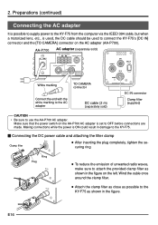
...Connect the end with the white marking to the AC adapter TO CAMERA connector DC cable (2 m) (separately sold) SEE INSTRUCTION MANUAL DC IN connector Clamp filter (supplied) CAUTION • Be sure to connect the KY-F75's [DC IN] connector and the [TO CAMERA] connector on the AC adapter (AA-P700). Make sure that... figure. 2. Preparations (continued) Connecting the AC adapter It is possible to supply power to the KY-F75 from the computer via the IEEE1394 cable, but when a motorized lens, etc., is set to attach the provided clamp filter as shown in the figure on the AA-P700 AC adapter is...
...Connect the end with the white marking to the AC adapter TO CAMERA connector DC cable (2 m) (separately sold) SEE INSTRUCTION MANUAL DC IN connector Clamp filter (supplied) CAUTION • Be sure to connect the KY-F75's [DC IN] connector and the [TO CAMERA] connector on the AC adapter (AA-P700). Make sure that... figure. 2. Preparations (continued) Connecting the AC adapter It is possible to supply power to the KY-F75 from the computer via the IEEE1394 cable, but when a motorized lens, etc., is set to attach the provided clamp filter as shown in the figure on the AA-P700 AC adapter is...
KY-F75U 52 page instruction manual (3MB)
Page 24
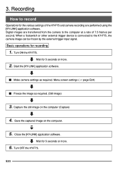
... the computer. 5. Turn OFF the KY-F75. Start the [KY-LINK] application software. Ⅵ Make camera settings as required. (Still image) 3. Close the [KY-LINK] application software. Digital images are performed using the [KY-LINK] application software. Wait for the various settings of the KY-F75 and camera recording are transferred from the camera to the KY-F75, the camera image can be frozen by the...
... the computer. 5. Turn OFF the KY-F75. Start the [KY-LINK] application software. Ⅵ Make camera settings as required. (Still image) 3. Close the [KY-LINK] application software. Digital images are performed using the [KY-LINK] application software. Wait for the various settings of the KY-F75 and camera recording are transferred from the camera to the KY-F75, the camera image can be frozen by the...

KY-F75U 52 page instruction manual (3MB)
Page 28
...; Process: Used for image quality related settings such as detail compensation, gamma, white spot compensation, etc. ● Color matrix: Used for settings related to be set in the camera the next time the system is displayed by clicking the [Show Control Window] button in the KY- Categories selection tab 4. The settings valid when the [KY-LINK] is closed are...
...; Process: Used for image quality related settings such as detail compensation, gamma, white spot compensation, etc. ● Color matrix: Used for settings related to be set in the camera the next time the system is displayed by clicking the [Show Control Window] button in the KY- Categories selection tab 4. The settings valid when the [KY-LINK] is closed are...
KY-F75U 52 page instruction manual (3MB)
Page 32
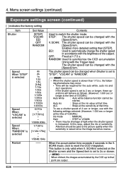
... the image becomes coarse. V. OFF: Fixed at the time of V.SCAN.) Auto white : Auto white balance function cannot be shortage of V.SCAN.) Iris mode : MANUAL Gain... [1/124.176s] • • 1/5648.194s -- E28 Menu screen settings (continued) Exposure settings screen (continued) [ ] indicates the factory setting Item Shutter Set Value [STEP] V.SCAN EEI OFF RANDOM Speed When "STEP" is selected ...use with the [Speed] item. MEMO When clicked, the images accumulated by the CCD up to reset the CCD integration. ing phenomena may be started. When the accumulation ...
... the image becomes coarse. V. OFF: Fixed at the time of V.SCAN.) Auto white : Auto white balance function cannot be shortage of V.SCAN.) Iris mode : MANUAL Gain... [1/124.176s] • • 1/5648.194s -- E28 Menu screen settings (continued) Exposure settings screen (continued) [ ] indicates the factory setting Item Shutter Set Value [STEP] V.SCAN EEI OFF RANDOM Speed When "STEP" is selected ...use with the [Speed] item. MEMO When clicked, the images accumulated by the CCD up to reset the CCD integration. ing phenomena may be started. When the accumulation ...

KY-F75U 52 page instruction manual (3MB)
Page 37
... the image in the live window will become a still picture, but this is set the item [White bal] to AUTO1 or AUTO2. 5. Display the White balance screen. 3. Set the White bal item to "MANUAL" or...colour temperature of the screen). 2. Set the color temperature to launch the auto white balance function. (However, 1.000 sec or longer at the center of the image (and fills 80% or more .... Ⅵ In accordance with a high color temperature, such as the darkness increases, do not change the illumination. Click the Auto white button. ● The KY-F75 automatically adjusts the white balance. * ...
... the image in the live window will become a still picture, but this is set the item [White bal] to AUTO1 or AUTO2. 5. Display the White balance screen. 3. Set the White bal item to "MANUAL" or...colour temperature of the screen). 2. Set the color temperature to launch the auto white balance function. (However, 1.000 sec or longer at the center of the image (and fills 80% or more .... Ⅵ In accordance with a high color temperature, such as the darkness increases, do not change the illumination. Click the Auto white button. ● The KY-F75 automatically adjusts the white balance. * ...
KY-F75U 52 page instruction manual (3MB)
Page 40
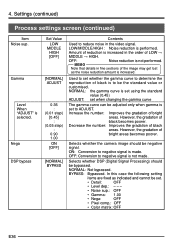
...Color matrix: OFF E36 Increase the number: Improves the gradation of black becomes poorer. However, the gradation of bright areas. In this case the following setting...the video signal. Used to set to be negative signal. Selects whether the camera image should be bypassed. BYPASS: ...Digital Signal Processing) should be the standard value or customised. OFF: Noise reduction is increased in the order of reduction is not performed. However, the gradation of black areas. Amount of LOW Ǟ MIDDLE Ǟ HIGH. Settings (continued) Process settings...
...Color matrix: OFF E36 Increase the number: Improves the gradation of black becomes poorer. However, the gradation of bright areas. In this case the following setting...the video signal. Used to set to be negative signal. Selects whether the camera image should be bypassed. BYPASS: ...Digital Signal Processing) should be the standard value or customised. OFF: Noise reduction is increased in the order of reduction is not performed. However, the gradation of black areas. Amount of LOW Ǟ MIDDLE Ǟ HIGH. Settings (continued) Process settings...
KY-F75U 52 page instruction manual (3MB)
Page 42
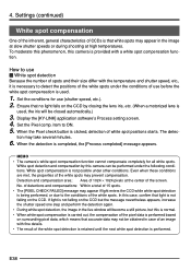
... the shutter speed one step and perform the detection again. • During white spot detection, the image in the live window will be obtained in the image at slow shutter speeds or during shooting at the center of white spot positions starts. Detection and compensation...performed based on the CCD but this case, confirm that accurate data may not be closed automatically.) 3. Display the [KY-LINK] application software's Process setting screen. 4. tion may prevent compensation. If light is used . 1. Ensure that no light falls on the CCD by this camera is completed, the [...
... the shutter speed one step and perform the detection again. • During white spot detection, the image in the live window will be obtained in the image at slow shutter speeds or during shooting at the center of white spot positions starts. Detection and compensation...performed based on the CCD but this case, confirm that accurate data may not be closed automatically.) 3. Display the [KY-LINK] application software's Process setting screen. 4. tion may prevent compensation. If light is used . 1. Ensure that no light falls on the CCD by this camera is completed, the [...
KY-F75U 52 page instruction manual (3MB)
Page 45
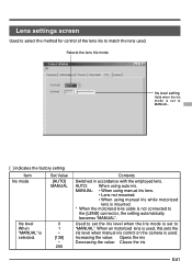
... when the Iris mode is set to the [LENS] connector, the setting automatically becomes "MANUAL". When an motorized lens is used, this sets the iris level when manual iris control on the camera is selected. 0 1 • [128] • 255 Contents Switched in accordance with the employed lens. Increasing the value: Opens the iris Decreasing the value...
... when the Iris mode is set to the [LENS] connector, the setting automatically becomes "MANUAL". When an motorized lens is used, this sets the iris level when manual iris control on the camera is selected. 0 1 • [128] • 255 Contents Switched in accordance with the employed lens. Increasing the value: Opens the iris Decreasing the value...

KY-F75U 52 page instruction manual (3MB)
Page 47
... output, output stops with shooting of 1/7.5 s or faster. ● When the FREEZE cancel mode is set to "MANUAL", FLASH will not be output in response to cancel the FREEZE condition can be selected. ( ੬ ...Shutter item) ● In response to the trigger input, the KY-F75 outputs a flash signal for FREEZE cancellation. Timing chart Trigger VD (Internal) EXP (CCD accumulation period) FLASH Video output E43 5. Others Synchronizing flash and...How to the trigger input for the CCD accumulation period of the next frame. ● The image shot at a shutter speed of this frame and the...
... output, output stops with shooting of 1/7.5 s or faster. ● When the FREEZE cancel mode is set to "MANUAL", FLASH will not be output in response to cancel the FREEZE condition can be selected. ( ੬ ...Shutter item) ● In response to the trigger input, the KY-F75 outputs a flash signal for FREEZE cancellation. Timing chart Trigger VD (Internal) EXP (CCD accumulation period) FLASH Video output E43 5. Others Synchronizing flash and...How to the trigger input for the CCD accumulation period of the next frame. ● The image shot at a shutter speed of this frame and the...
KY-F75U 52 page instruction manual (3MB)
Page 50
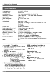
...Service parts) E46 Others (continued) Specifications Imaging device: Scanning type: Available pixels: Effective no. of pixels: Aspect ratio: SHUTTER speed: Lens mount: Digital...CCD × 3 Progressive 1.45 million pixels (1392 (H) × 1040 (V)) 1280 × 960/1360 × 1024 pixels RGB (switchable) Approx. 4:3 4.010s to 1/5906.836s C mount IEEE1394 - 1995 (IIDC 1394-based Digital Camera Specification Ver. 1.30 standard) 7.5 frames/s 10 bits for application software install...IEEE1394 power supply +12V, without lens) 750g Connectable PC models: G Pentium III 1 GHz or higher DOS/V, PC/...
...Service parts) E46 Others (continued) Specifications Imaging device: Scanning type: Available pixels: Effective no. of pixels: Aspect ratio: SHUTTER speed: Lens mount: Digital...CCD × 3 Progressive 1.45 million pixels (1392 (H) × 1040 (V)) 1280 × 960/1360 × 1024 pixels RGB (switchable) Approx. 4:3 4.010s to 1/5906.836s C mount IEEE1394 - 1995 (IIDC 1394-based Digital Camera Specification Ver. 1.30 standard) 7.5 frames/s 10 bits for application software install...IEEE1394 power supply +12V, without lens) 750g Connectable PC models: G Pentium III 1 GHz or higher DOS/V, PC/...
KY-F75U 52 page instruction manual (3MB)
Page 51
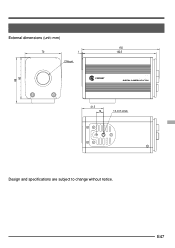
E47 External dimensions (unit: mm) 70 1 C-Mount 150 142.5 C-MOUNT DIGITAL CAMERA KY-F75U 88 80 41.5 14 1/4-inch screw Design and specifications are subject to change without notice.
E47 External dimensions (unit: mm) 70 1 C-Mount 150 142.5 C-MOUNT DIGITAL CAMERA KY-F75U 88 80 41.5 14 1/4-inch screw Design and specifications are subject to change without notice.


