Instruction Manual
Page 1
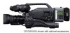
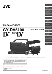
...purchasing this unit, please read the instructions carefully to ensure the best possible performance. Model No. GY-DV5100 Serial No. LWT0230-001A-H DV CAMCORDER GY-DV5100 INTRODUCTION CONTROLS, INDICATORS AND CONNECTORS BASIC SYSTEM CONNECTIONS AND ADJUSTMENTS POWER SUPPLY PREPARATIONS SETTING AND ADJUSTMENTS...FEATURES OF THE CAMERA SECTION OTHERS * The illustration shows the GY-DV5100 DV Camcorder with the optional lens, viewfinder and Microphone attached. For Customer Use : Enter below the Serial No. Before operating this JVC product. which is located on the body. Thank you ...
...purchasing this unit, please read the instructions carefully to ensure the best possible performance. Model No. GY-DV5100 Serial No. LWT0230-001A-H DV CAMCORDER GY-DV5100 INTRODUCTION CONTROLS, INDICATORS AND CONNECTORS BASIC SYSTEM CONNECTIONS AND ADJUSTMENTS POWER SUPPLY PREPARATIONS SETTING AND ADJUSTMENTS...FEATURES OF THE CAMERA SECTION OTHERS * The illustration shows the GY-DV5100 DV Camcorder with the optional lens, viewfinder and Microphone attached. For Customer Use : Enter below the Serial No. Before operating this JVC product. which is located on the body. Thank you ...
Instruction Manual
Page 4
.... ● Camera section designed with 3-CCD system for high-quality picture 1/2" 3-CCD with the symbol or symbol can be ... copyright holders. ● JVC cannot assume liabilities that both standard-size DV videocassettes and mini-size DV videocassettes Recording/playback can only... for GY-DV5100U. Other use of video or audio due to 2084.6 Hz. ● DV (i. This is a DV video system format camcorder. LINK) connector DV connector...made to other equipment provided with DV connector, such as a non-linear editing system. ● 1/2" bayonet type lens ● Camera output, VCR playback...
.... ● Camera section designed with 3-CCD system for high-quality picture 1/2" 3-CCD with the symbol or symbol can be ... copyright holders. ● JVC cannot assume liabilities that both standard-size DV videocassettes and mini-size DV videocassettes Recording/playback can only... for GY-DV5100U. Other use of video or audio due to 2084.6 Hz. ● DV (i. This is a DV video system format camcorder. LINK) connector DV connector...made to other equipment provided with DV connector, such as a non-linear editing system. ● 1/2" bayonet type lens ● Camera output, VCR playback...

Instruction Manual
Page 5
...Setup According to Illumination and Subject 93 12-7 How to be Used 8 1-6 Condensation 9 1-7 Characteristic CCD Phenomena 9 2. BASIC SYSTEM CONNECTIONS AND ADJUSTMENTS 3-1 Basic System 31 3-2 Attaching the Zoom Lens 32 3-3 Attaching the Viewfinder 32 3-4 Attaching the Microphone (Provided 33 3-5 Attaching the Microphone (Optional ...13 TIME/DATE Menu Screen 85 11-14 OTHERS Menu Screen 86 12. USING EXTERNAL COMPONENTS 9-1 Connecting a Video Component with DV Connector 65 10. OTHERS 13-1 Alarm Indications and Actions 96 13-2 Troubleshooting 99 13-3 Hour Meter Display 100 13-4 ...
...Setup According to Illumination and Subject 93 12-7 How to be Used 8 1-6 Condensation 9 1-7 Characteristic CCD Phenomena 9 2. BASIC SYSTEM CONNECTIONS AND ADJUSTMENTS 3-1 Basic System 31 3-2 Attaching the Zoom Lens 32 3-3 Attaching the Viewfinder 32 3-4 Attaching the Microphone (Provided 33 3-5 Attaching the Microphone (Optional ...13 TIME/DATE Menu Screen 85 11-14 OTHERS Menu Screen 86 12. USING EXTERNAL COMPONENTS 9-1 Connecting a Video Component with DV Connector 65 10. OTHERS 13-1 Alarm Indications and Actions 96 13-2 Troubleshooting 99 13-3 Hour Meter Display 100 13-4 ...
Instruction Manual
Page 6
... Supply voltage Make sure that the unit returns to remove the detergent. In addition, salt and sand may adhere to the optical performance of the lens, color divergence phenomena (magnification chromatic aberration) may be damaged. ● The sensitivity level of the provided microphone is provided with it with a ...dry, soft cloth. When it in the rain). ● Protect the unit from being wet when shooting on the CCD elements could pick up noise. ● Avoid using or placing the unit in places; • subject to extreme heat or cold; • with...
... Supply voltage Make sure that the unit returns to remove the detergent. In addition, salt and sand may adhere to the optical performance of the lens, color divergence phenomena (magnification chromatic aberration) may be damaged. ● The sensitivity level of the provided microphone is provided with it with a ...dry, soft cloth. When it in the rain). ● Protect the unit from being wet when shooting on the CCD elements could pick up noise. ● Avoid using or placing the unit in places; • subject to extreme heat or cold; • with...
Instruction Manual
Page 7
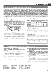
...operating environment and method. Note 3) Use the cleaning tape in charge of professional video equipment at your nearest JVC-authorized service agent. 1-3 Precautions for Use of Head Cleaning Tape Please use...differ from the contents of this sheet. INTRODUCTION 1-2 Routine and Periodical Maintenance The GY-DV5100 incorporates precision mechanical parts, which will promote the wear and deterioration of the...Press the PLAY button after repeated head cleanings, the recording tape may remain on the lens section. Note 1) When used . does not disappear after the cleaning tape is ...
...operating environment and method. Note 3) Use the cleaning tape in charge of professional video equipment at your nearest JVC-authorized service agent. 1-3 Precautions for Use of Head Cleaning Tape Please use...differ from the contents of this sheet. INTRODUCTION 1-2 Routine and Periodical Maintenance The GY-DV5100 incorporates precision mechanical parts, which will promote the wear and deterioration of the...Press the PLAY button after repeated head cleanings, the recording tape may remain on the lens section. Note 1) When used . does not disappear after the cleaning tape is ...
Instruction Manual
Page 10
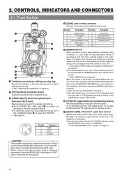
...adjustment of the CH-1 audio signal input. Function 1 Return switch 7 Iris position 2 VTR trigger 8 IRIS A/R INPUT 3 GND 9 EXTENDER position 4 Lens AUTO/MANU control 10 ZOOM position 5 IRIS control 11 - 6 +12V DC 12 - 5 [ZEBRA] Switch When this connector, set the CH-1/ CH... control, set to "FRONT". ☞ See page 16. 1 3 2 Pin No. 1 2 3 Function GND HOT COLD 4 [LENS] Lens control connector Connect 12-pin lens control cable from the viewfinder here. 3 [FRONT MIC IN] Front microphone input connector (XLR 3-pin) Balanced 3-pin connector for camera microphone...
...adjustment of the CH-1 audio signal input. Function 1 Return switch 7 Iris position 2 VTR trigger 8 IRIS A/R INPUT 3 GND 9 EXTENDER position 4 Lens AUTO/MANU control 10 ZOOM position 5 IRIS control 11 - 6 +12V DC 12 - 5 [ZEBRA] Switch When this connector, set the CH-1/ CH... control, set to "FRONT". ☞ See page 16. 1 3 2 Pin No. 1 2 3 Function GND HOT COLD 4 [LENS] Lens control connector Connect 12-pin lens control cable from the viewfinder here. 3 [FRONT MIC IN] Front microphone input connector (XLR 3-pin) Balanced 3-pin connector for camera microphone...

Instruction Manual
Page 11
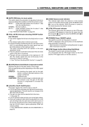
... (such as a fluorescent lamp, etc.) • This operation is pressed down to turn the ring clockwise until firm. ☞ See "Attaching the Zoom Lens" on page 32. 0 [FILTER] Color temperature conversion filter control knob This knob switches the internal color temperature filters. (3200K, 5600K + 1/8ND, 5600K,... 5600K + 1/64ND) ☞ See "Camera Settings" on page 50. 2. To mount lens make sure the lens guide pin fits well, and then turn the ring anticlockwise to open for white balance. * It is not activated in the LOLUX mode...
... (such as a fluorescent lamp, etc.) • This operation is pressed down to turn the ring clockwise until firm. ☞ See "Attaching the Zoom Lens" on page 32. 0 [FILTER] Color temperature conversion filter control knob This knob switches the internal color temperature filters. (3200K, 5600K + 1/8ND, 5600K,... 5600K + 1/64ND) ☞ See "Camera Settings" on page 50. 2. To mount lens make sure the lens guide pin fits well, and then turn the ring anticlockwise to open for white balance. * It is not activated in the LOLUX mode...
Instruction Manual
Page 13
...18 dB. Set to an appropriate position depending on page 93. 9 [CAM] Camera mode indicator This indicator lights when the camera is turned on the lens section.) 7 [BLACK] Black stretch/black compression switch Switches the gain for the dark section of a second. ☞ See "Full Auto Shooting (FAS... LOLUX CONDITION" on and off . * Wait 5 seconds or more before turning the power on this indicator. To perform VTR playback or input the DV signal from the standard level.) ☞ See "SWITCH FUNCTIONS" on page 93. 6 [FULL AUTO] Full auto shooting ON/OFF button and indicator ...
...18 dB. Set to an appropriate position depending on page 93. 9 [CAM] Camera mode indicator This indicator lights when the camera is turned on the lens section.) 7 [BLACK] Black stretch/black compression switch Switches the gain for the dark section of a second. ☞ See "Full Auto Shooting (FAS... LOLUX CONDITION" on and off . * Wait 5 seconds or more before turning the power on this indicator. To perform VTR playback or input the DV signal from the standard level.) ☞ See "SWITCH FUNCTIONS" on page 93. 6 [FULL AUTO] Full auto shooting ON/OFF button and indicator ...
Instruction Manual
Page 17
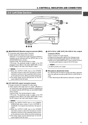
CONTROLS, INDICATORS AND CONNECTORS r LINE OUT CH-1 Y/C OUT MONITOR OUT CH-2 ewq FRONT MIC IN LENS 1 [MONITOR OUT] Monitor output connector (BNC) ● Composite video signal output connector. ● Video signals with setup level are output. (Whether or not setup level ... be shown on the external monitor. (Black and white indications) ● The setup signal can be selected also for the EE output signal of the DV input. 3 [CH-1/CH-2 LINE OUT] CH-1/CH-2 line output connector (RCA) Output connector for audio signals. ● Outputs the input audio signal in the Camera...
CONTROLS, INDICATORS AND CONNECTORS r LINE OUT CH-1 Y/C OUT MONITOR OUT CH-2 ewq FRONT MIC IN LENS 1 [MONITOR OUT] Monitor output connector (BNC) ● Composite video signal output connector. ● Video signals with setup level are output. (Whether or not setup level ... be shown on the external monitor. (Black and white indications) ● The setup signal can be selected also for the EE output signal of the DV input. 3 [CH-1/CH-2 LINE OUT] CH-1/CH-2 line output connector (RCA) Output connector for audio signals. ● Outputs the input audio signal in the Camera...
Instruction Manual
Page 24
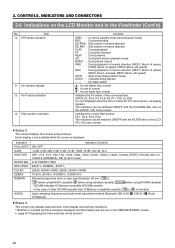
... this screen is removed. For some lenses, no display appears. OPEN, F2, F2.8, F4, F5.6, F8, F11, F16, CLOSE It is not displayed when the lens is displayed. Indication FULL AUTO GAIN SHUTTER WHITE BAL IRIS LEVEL FILTER ZEBRA REMAIN AUDIO Indication Contents ON, OFF -3 dB, 0 dB, 3dB, 6 dB, 9 dB, 12... the Time and Date on the LCD/VF (1/2) menu screen. In the case of other DVCAM cassette than normal Indicates the F-number of the connected lens.
... this screen is removed. For some lenses, no display appears. OPEN, F2, F2.8, F4, F5.6, F8, F11, F16, CLOSE It is not displayed when the lens is displayed. Indication FULL AUTO GAIN SHUTTER WHITE BAL IRIS LEVEL FILTER ZEBRA REMAIN AUDIO Indication Contents ON, OFF -3 dB, 0 dB, 3dB, 6 dB, 9 dB, 12... the Time and Date on the LCD/VF (1/2) menu screen. In the case of other DVCAM cassette than normal Indicates the F-number of the connected lens.

Instruction Manual
Page 29
...zoom control by the zoom servo control lever 6. Secure with a clear filter or UV filter by screwing the filter onto the thread inside the lens hood from the VTR section can be monitored in the viewfinder, LCD and MONITOR OUT while this button is pushed. * The playback picture can ...be viewed in the macro mode. To avoid the phenomena described above, perform adjustment again. 0 FILTER thread Protect the lens with the screw knob after adjustment. ☞ See "Back Focus Adjustment" on page 49. 29 Normal focus adjustment and zooming are not available in ...
...zoom control by the zoom servo control lever 6. Secure with a clear filter or UV filter by screwing the filter onto the thread inside the lens hood from the VTR section can be monitored in the viewfinder, LCD and MONITOR OUT while this button is pushed. * The playback picture can ...be viewed in the macro mode. To avoid the phenomena described above, perform adjustment again. 0 FILTER thread Protect the lens with the screw knob after adjustment. ☞ See "Back Focus Adjustment" on page 49. 29 Normal focus adjustment and zooming are not available in ...
Instruction Manual
Page 31
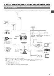
...-P618U 3P MIC HOLDER KA-A50U VIDEO LIGHT (ANTON BAUER. 3. PROTEC) 1.5" VIEW FINDER VF-P115B VF-P116 DV CAMCORDER ZOOM LENS S14 × 7.3B12U(FUJINON) S17 × 6.6BRM(FUJINON) S20 × 6.4B12U(FUJINON) YH16 ×... REAR CH-1 CH-2 AUDIO IN AUDIO SELECT CH-1 CH-2 AUTO MANUAL DISPLAY PULL OPEN GY-DV5100 STANDARD PACKAGE TRIPOD BASE FOCUS MANUAL UNIT *1 HZ-FM13 (FUJINON) HZ-FM15 (CANON...CASE DOLLY TP-P205 ANTON BAUER ANTON BAUER BATTERY BATTERY HOLDER (PRO PAC, MAGNUM, (QR JVC DIGI) TRIMPAC, HYTRON) ANTON BAUER BATTERY CHARGER BATTERY NP-1B TYPE BATTERY CHARGER 4P 4P ...
...-P618U 3P MIC HOLDER KA-A50U VIDEO LIGHT (ANTON BAUER. 3. PROTEC) 1.5" VIEW FINDER VF-P115B VF-P116 DV CAMCORDER ZOOM LENS S14 × 7.3B12U(FUJINON) S17 × 6.6BRM(FUJINON) S20 × 6.4B12U(FUJINON) YH16 ×... REAR CH-1 CH-2 AUDIO IN AUDIO SELECT CH-1 CH-2 AUTO MANUAL DISPLAY PULL OPEN GY-DV5100 STANDARD PACKAGE TRIPOD BASE FOCUS MANUAL UNIT *1 HZ-FM13 (FUJINON) HZ-FM15 (CANON...CASE DOLLY TP-P205 ANTON BAUER ANTON BAUER BATTERY BATTERY HOLDER (PRO PAC, MAGNUM, (QR JVC DIGI) TRIMPAC, HYTRON) ANTON BAUER BATTERY CHARGER BATTERY NP-1B TYPE BATTERY CHARGER 4P 4P ...

Instruction Manual
Page 32
...connector. 3. Attach the viewfinder with its pin aligned with the left or the right eye. Tighten the stopper screw. 5. Attach the lens with its guide aligned with an hexagon wrench (Provided) and then remove the viewfinder mount base (including the sliding securing ring). 2. ... 3. Sliding securing ring 2. 32 ■ Observing the viewfinder with the hole in the lens dropping off or disturbed back focus. ● Set the GY-DV5100's power switch to "OFF" before the zoom lens is attached or detached. Loosen the sliding securing ring. 2. Connector 1. Remove the cap....
...connector. 3. Attach the viewfinder with its pin aligned with the left or the right eye. Tighten the stopper screw. 5. Attach the lens with its guide aligned with an hexagon wrench (Provided) and then remove the viewfinder mount base (including the sliding securing ring). 2. ... 3. Sliding securing ring 2. 32 ■ Observing the viewfinder with the hole in the lens dropping off or disturbed back focus. ● Set the GY-DV5100's power switch to "OFF" before the zoom lens is attached or detached. Loosen the sliding securing ring. 2. Connector 1. Remove the cap....
Instruction Manual
Page 38
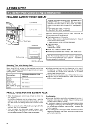
...; BACK TALLY lamp on Camera : Blinks ■ Monitoring loudspeaker and PHONES jack: Alarm sound After the remaining battery power warnings appear, the GY-DV5100 automatically stops operation if the battery power operation is not in use , recharging may differ depending on the left for approximate reference times....gets dirty, the operating time will be stored in areas with a cold environment. ● Operating time is reduced when the power zoom lens and LCD are used as the viewfinder and a fully charged battery pack is attached, the approximate continuous operating time is as follows: ...
...; BACK TALLY lamp on Camera : Blinks ■ Monitoring loudspeaker and PHONES jack: Alarm sound After the remaining battery power warnings appear, the GY-DV5100 automatically stops operation if the battery power operation is not in use , recharging may differ depending on the left for approximate reference times....gets dirty, the operating time will be stored in areas with a cold environment. ● Operating time is reduced when the power zoom lens and LCD are used as the viewfinder and a fully charged battery pack is attached, the approximate continuous operating time is as follows: ...
Instruction Manual
Page 47
... dial, set to fit 4:3 screens. MODE switch: Camera mode (CAM indicator should be selected with the upper and lower parts of the unit. Set the lens' iris mode switch to OFF (1/60). B. [GAIN] switch: Set to A or B. 3. The L position is set the shutter speed to "A" (AUTO IRIS side) 4. In this case...
... dial, set to fit 4:3 screens. MODE switch: Camera mode (CAM indicator should be selected with the upper and lower parts of the unit. Set the lens' iris mode switch to OFF (1/60). B. [GAIN] switch: Set to A or B. 3. The L position is set the shutter speed to "A" (AUTO IRIS side) 4. In this case...

Instruction Manual
Page 49
...ring. Loosen the back focus ring retaining knob. 8. about three times for fine adjustment until the lens is more than 3 meters from the camera. 6. The optimal subject for this when the lens is attached for the best possible focus. 9. Set the IRIS mode switch to M (Manual). 3.... Set the zoom mode to M (Manual). 2. Bring the subject into focus. 6. Set the lens to perform this adjustment is a Siemens star chart. MEMO:...
...ring. Loosen the back focus ring retaining knob. 8. about three times for fine adjustment until the lens is more than 3 meters from the camera. 6. The optimal subject for this when the lens is attached for the best possible focus. 9. Set the IRIS mode switch to M (Manual). 3.... Set the zoom mode to M (Manual). 2. Bring the subject into focus. 6. Set the lens to perform this adjustment is a Siemens star chart. MEMO:...

Instruction Manual
Page 50
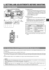
.... Place a white object near the centre of light (color temperature) varies depending on an object or the color temperature is inferior to that of the lens to fill the screen with the FAW item on with a color temperature of places under the same lighting conditions as this interval. 50 When correct...
.... Place a white object near the centre of light (color temperature) varies depending on an object or the color temperature is inferior to that of the lens to fill the screen with the FAW item on with a color temperature of places under the same lighting conditions as this interval. 50 When correct...

Instruction Manual
Page 55
... shooting starts in order to the tape protect mode. ☞ See "LONG PAUSE TIME item on the OTHERS (1/2) menu screen" on the GY-DV5100 or lens. 10.Ending recording: Press the VTR trigger button to enter the record-standby mode and perform the following operations as required. ■ When it... long period, detach the battery pack. VTR trigger button 8. If the sound is found annoying, please purchase an optional microphone in the middle of the lens' iris if the iris is not going to be used for about 2 seconds (back-spacing). 9. SHOOTING OPERATION REC BATT ALARM 7.8 8. The TALLY...
... shooting starts in order to the tape protect mode. ☞ See "LONG PAUSE TIME item on the OTHERS (1/2) menu screen" on the GY-DV5100 or lens. 10.Ending recording: Press the VTR trigger button to enter the record-standby mode and perform the following operations as required. ■ When it... long period, detach the battery pack. VTR trigger button 8. If the sound is found annoying, please purchase an optional microphone in the middle of the lens' iris if the iris is not going to be used for about 2 seconds (back-spacing). 9. SHOOTING OPERATION REC BATT ALARM 7.8 8. The TALLY...

Instruction Manual
Page 57
...tape protect mode, STOP is rewound and played back for approximately 2 seconds. In the record-standby mode, press the RET button on the camera lens section. • The tape is shown on the LCD monitor or in the viewfinder or on the LCD monitor and in the standby mode. ... AM01:23:45 VTR mode indication 7-4 Checking Recorded Contents in Record-Standby Mode (Recording Check Function) RET button This function is available only when the GY-DV5100 is in the viewfinder screen. (Status 1 screen) ■ To start recording from the tape protect mode, press the VTR trigger button. ●...
...tape protect mode, STOP is rewound and played back for approximately 2 seconds. In the record-standby mode, press the RET button on the camera lens section. • The tape is shown on the LCD monitor or in the viewfinder or on the LCD monitor and in the standby mode. ... AM01:23:45 VTR mode indication 7-4 Checking Recorded Contents in Record-Standby Mode (Recording Check Function) RET button This function is available only when the GY-DV5100 is in the viewfinder screen. (Status 1 screen) ■ To start recording from the tape protect mode, press the VTR trigger button. ●...

Instruction Manual
Page 78
... (5) 4 to NORMAL (0) to -4 MIN (-5) OFF NORMAL FLARE For correcting the entire black level when the flare phenomenon in which light entering the lens is at this position switches the screen to ON, color reproduction becomes good. Decrease the number Note: When LOLUX is ON, "FIX" is displayed and...tinge EXTRA 1 to set a color matrix other that colors the black portions of Bch when the flare phenomenon in which light entering the lens is diffused and results in reflection that those described above. 11. To raise the entire black level...Increase the number To lessen the ...
... (5) 4 to NORMAL (0) to -4 MIN (-5) OFF NORMAL FLARE For correcting the entire black level when the flare phenomenon in which light entering the lens is at this position switches the screen to ON, color reproduction becomes good. Decrease the number Note: When LOLUX is ON, "FIX" is displayed and...tinge EXTRA 1 to set a color matrix other that colors the black portions of Bch when the flare phenomenon in which light entering the lens is diffused and results in reflection that those described above. 11. To raise the entire black level...Increase the number To lessen the ...


