Instruction Manual
Page 1
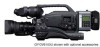
... Retain this information for purchasing this unit, please read the instructions carefully to ensure the best possible performance. LWT0230-001A-H DV CAMCORDER GY-DV5100 INTRODUCTION CONTROLS, INDICATORS AND CONNECTORS BASIC SYSTEM CONNECTIONS AND ADJUSTMENTS POWER SUPPLY PREPARATIONS SETTING AND ADJUSTMENTS BEFORE SHOOTING SHOOTING OPERATION ... COMPONENTS TIME CODE OPERATION MENU SCREENS FEATURES OF THE CAMERA SECTION OTHERS * The illustration shows the GY-DV5100 DV Camcorder with the optional lens, viewfinder and Microphone attached. Model No. Before operating this...
... Retain this information for purchasing this unit, please read the instructions carefully to ensure the best possible performance. LWT0230-001A-H DV CAMCORDER GY-DV5100 INTRODUCTION CONTROLS, INDICATORS AND CONNECTORS BASIC SYSTEM CONNECTIONS AND ADJUSTMENTS POWER SUPPLY PREPARATIONS SETTING AND ADJUSTMENTS BEFORE SHOOTING SHOOTING OPERATION ... COMPONENTS TIME CODE OPERATION MENU SCREENS FEATURES OF THE CAMERA SECTION OTHERS * The illustration shows the GY-DV5100 DV Camcorder with the optional lens, viewfinder and Microphone attached. Model No. Before operating this...
Instruction Manual
Page 4
...moves in compatible mechanism for high-quality picture 1/2" 3-CCD with shooting conditions which varies as you for purchasing the DV Camcorder GY-DV5100. Recording in the unit. ● Recording... Employment of aluminum die-casting has resulted in monitor speaker for GY-DV5100U. Digital signal processing for reproduction of DV high-quality picture. ● LOLUX for difficult shooting conditions with...the rights of copyright holders. ● JVC cannot assume liabilities that both standard-size DV videocassettes and mini-size DV videocassettes Recording/playback can be used to record...
...moves in compatible mechanism for high-quality picture 1/2" 3-CCD with shooting conditions which varies as you for purchasing the DV Camcorder GY-DV5100. Recording in the unit. ● Recording... Employment of aluminum die-casting has resulted in monitor speaker for GY-DV5100U. Digital signal processing for reproduction of DV high-quality picture. ● LOLUX for difficult shooting conditions with...the rights of copyright holders. ● JVC cannot assume liabilities that both standard-size DV videocassettes and mini-size DV videocassettes Recording/playback can be used to record...

Instruction Manual
Page 5
... 8-5 Variable Slow Playback 63 8-6 Outputting CH-3, CH-4 Channel Audio 64 APPLICATION 9. USING EXTERNAL COMPONENTS 9-1 Connecting a Video Component with DV Connector 65 10. FEATURES OF THE CAMERA SECTION 12-1 Full-Time Auto White Balance (FAW 88 12-2 IRIS (Brightness) Adjustment 89 ... (Sensitivity) Adjustment 92 12-6 Switch Setup According to Illumination and Subject 93 12-7 How to be Used 8 1-6 Condensation 9 1-7 Characteristic CCD Phenomena 9 2. POWER SUPPLY 4-1 AC Operation 35 4-2 Battery Pack Operation (Optional 35 BASIC OPERATIONS 5. TIME CODE OPERATION 10-1 Displaying Time ...
... 8-5 Variable Slow Playback 63 8-6 Outputting CH-3, CH-4 Channel Audio 64 APPLICATION 9. USING EXTERNAL COMPONENTS 9-1 Connecting a Video Component with DV Connector 65 10. FEATURES OF THE CAMERA SECTION 12-1 Full-Time Auto White Balance (FAW 88 12-2 IRIS (Brightness) Adjustment 89 ... (Sensitivity) Adjustment 92 12-6 Switch Setup According to Illumination and Subject 93 12-7 How to be Used 8 1-6 Condensation 9 1-7 Characteristic CCD Phenomena 9 2. POWER SUPPLY 4-1 AC Operation 35 4-2 Battery Pack Operation (Optional 35 BASIC OPERATIONS 5. TIME CODE OPERATION 10-1 Displaying Time ...

Instruction Manual
Page 8
...: LA-DV276, LA-DV186, LADV124 Mini DV videocassette: M-DV63PRO, M-DV60, M-DV30 * Do not use M-DV80. ● Videocassettes cannot be Used ● Use JVC's videocassette tapes marked with the " " or " " symbol. It is recommended that videotapes be unspooled and rewound once a year for refreshing. ●...care of the conditions of the battery pack in cases and on page 82. * A flat shape type battery pack cannot be Used The GY-DV5100 can cause distortions and deformations of time, it may cause tape-to protect the required recording in distortion of videotapes. Storage cases protect...
...: LA-DV276, LA-DV186, LADV124 Mini DV videocassette: M-DV63PRO, M-DV60, M-DV30 * Do not use M-DV80. ● Videocassettes cannot be Used ● Use JVC's videocassette tapes marked with the " " or " " symbol. It is recommended that videotapes be unspooled and rewound once a year for refreshing. ●...care of the conditions of the battery pack in cases and on page 82. * A flat shape type battery pack cannot be Used The GY-DV5100 can cause distortions and deformations of time, it may cause tape-to protect the required recording in distortion of videotapes. Storage cases protect...
Instruction Manual
Page 13
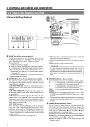
...light (Opens the iris about 1 step from the standard level.) NORMAL : Normal condition SPOT L : Under spotlight (Closes the iris about 1 step from the DV connector 7 on page 19, press the MODE switch F to increase the contrast. 8 [LOLUX] LOLUX On/Off button This button toggles the LOLUX mode on ... position depending on and off . ● LOLUX gain gives extremely low light level sensitivity for special applications. To perform VTR playback or input the DV signal from the standard level.) ☞ See "SWITCH FUNCTIONS" on page 93. 6 [FULL AUTO] Full auto shooting ON/OFF button and indicator...
...light (Opens the iris about 1 step from the standard level.) NORMAL : Normal condition SPOT L : Under spotlight (Closes the iris about 1 step from the DV connector 7 on page 19, press the MODE switch F to increase the contrast. 8 [LOLUX] LOLUX On/Off button This button toggles the LOLUX mode on ... position depending on and off . ● LOLUX gain gives extremely low light level sensitivity for special applications. To perform VTR playback or input the DV signal from the standard level.) ☞ See "SWITCH FUNCTIONS" on page 93. 6 [FULL AUTO] Full auto shooting ON/OFF button and indicator...
Instruction Manual
Page 14
...camera. Set to the landscape out through a window. ● When shooting a human being in accordance with white. When the video signal from the DV connector 7 on page 19. ● When the power is turned on the switch position as a human being, etc., with a high-brightness background...; When shooting a high-contrast scene. In this mode, the auto knee function is available. It is set the auto knee function to input the DV signal from the shooting camera is selected, the auto knee function is not available. CAM. 2. PRST : A non-erasable white balance setting at 3200K...
...camera. Set to the landscape out through a window. ● When shooting a human being in accordance with white. When the video signal from the DV connector 7 on page 19. ● When the power is turned on the switch position as a human being, etc., with a high-brightness background...; When shooting a high-contrast scene. In this mode, the auto knee function is available. It is set the auto knee function to input the DV signal from the shooting camera is selected, the auto knee function is not available. CAM. 2. PRST : A non-erasable white balance setting at 3200K...
Instruction Manual
Page 17
... and white indications) ● The setup signal can be selected also for the EE output signal of the DV input. 3 [CH-1/CH-2 LINE OUT] CH-1/CH-2 line output connector (RCA) Output connector for audio ... Output connector for the EE output signal of the input audio signal is output in the VTR mode. When a DV signal (IEEE1394) is input, the EE image of the input video signal is output. MEMO: ● When ...screen.) Camera mode: The camera image is output. MEMO: ● When the OUTPUT CHAR. When a DV signal (IEEE1394) is input, the EE image of the input video signal is set to ON, the...
... and white indications) ● The setup signal can be selected also for the EE output signal of the DV input. 3 [CH-1/CH-2 LINE OUT] CH-1/CH-2 line output connector (RCA) Output connector for audio ... Output connector for the EE output signal of the input audio signal is output in the VTR mode. When a DV signal (IEEE1394) is input, the EE image of the input video signal is output. MEMO: ● When ...screen.) Camera mode: The camera image is output. MEMO: ● When the OUTPUT CHAR. When a DV signal (IEEE1394) is input, the EE image of the input video signal is set to ON, the...

Instruction Manual
Page 19
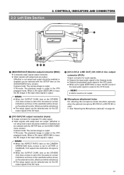
...-1/CH-2 REAR AUDIO IN switch B on page 16. This connector is selected with DV connector. To record the DV signal from a digital video component with the AUDIO SELECT item on the AUDIO/VIDEO menu... screen and MONITOR SELECT switch C on page 16 in accordance with DV connector can be output, the following setting should light and the lighting pattern. ☞ See "BACK...CH-2 REAR AUDIO IN q re w 1 [TALLY] Tally lamp This lamp lights up when the GY-DV5100 enters the record mode. When a cable is connected here, the power supply from this connector. ...
...-1/CH-2 REAR AUDIO IN switch B on page 16. This connector is selected with DV connector. To record the DV signal from a digital video component with the AUDIO SELECT item on the AUDIO/VIDEO menu... screen and MONITOR SELECT switch C on page 16 in accordance with DV connector can be output, the following setting should light and the lighting pattern. ☞ See "BACK...CH-2 REAR AUDIO IN q re w 1 [TALLY] Tally lamp This lamp lights up when the GY-DV5100 enters the record mode. When a cable is connected here, the power supply from this connector. ...

Instruction Manual
Page 21
... Camera mode (Example of display) STBY FAS 6dB FAW I SD B 48k 12.2V 01/02/03 01:23:45 STATUS 1 ● VTR mode (DV signal input mode) (Example of screen is displayed. MEMO: ● When the STATUS button is pressed for the VTR mode. ● Each time the ...■ Alarm message display ■ Auto white display (only displayed in the Camera mode) ■ Safety zone display (only displayed in the VTR mode (DV signal input mode). 2. CONTROLS, INDICATORS AND CONNECTORS 2-6 Indications on the LCD monitor, press the DISPLAY button briefly. ■ Status screens (screens for the ...
... Camera mode (Example of display) STBY FAS 6dB FAW I SD B 48k 12.2V 01/02/03 01:23:45 STATUS 1 ● VTR mode (DV signal input mode) (Example of screen is displayed. MEMO: ● When the STATUS button is pressed for the VTR mode. ● Each time the ...■ Alarm message display ■ Auto white display (only displayed in the Camera mode) ■ Safety zone display (only displayed in the VTR mode (DV signal input mode). 2. CONTROLS, INDICATORS AND CONNECTORS 2-6 Indications on the LCD monitor, press the DISPLAY button briefly. ■ Status screens (screens for the ...

Instruction Manual
Page 22
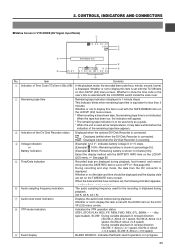
... date and time Indicates the date and time. Item Contents 1 Indication of the DV Disk Recorder status Displayed when the optional DV Disk Recorder is connected. : Displayed (white) when the DV Disk Recorder is connected. ● : Displayed (red) when the DV Disk Recorder is ON. 5 Indication of -5, -4, -3, -2, -1, 0, +1, +2, +3, +4, +5. 22 Whether or not the date and...
... date and time Indicates the date and time. Item Contents 1 Indication of the DV Disk Recorder status Displayed when the optional DV Disk Recorder is connected. : Displayed (white) when the DV Disk Recorder is connected. ● : Displayed (red) when the DV Disk Recorder is ON. 5 Indication of -5, -4, -3, -2, -1, 0, +1, +2, +3, +4, +5. 22 Whether or not the date and...
Instruction Manual
Page 25
...second, frame) is not indicated. Item Contents 1 Indication of the DV Disk Recorder status Displayed when the optional DV Disk Recorder is connected. : Displayed (white) when the DV Disk Recorder is connected. ● : Displayed (red) when the DV Disk Recorder is recording. 4 Voltage indication or Battery indication (Example)... time have not been set with the COUNTER switch inside the side cover. 2 Remaining tape time Remaining tape indication (displayed in VTR MODE (DV Signal Input Mode) 1 00:00:00:00 20min 2 DD 3 9 Event display area 6 48k 12.2V 4 8 PLAY 01/02/03...
...second, frame) is not indicated. Item Contents 1 Indication of the DV Disk Recorder status Displayed when the optional DV Disk Recorder is connected. : Displayed (white) when the DV Disk Recorder is connected. ● : Displayed (red) when the DV Disk Recorder is recording. 4 Voltage indication or Battery indication (Example)... time have not been set with the COUNTER switch inside the side cover. 2 Remaining tape time Remaining tape indication (displayed in VTR MODE (DV Signal Input Mode) 1 00:00:00:00 20min 2 DD 3 9 Event display area 6 48k 12.2V 4 8 PLAY 01/02/03...

Instruction Manual
Page 27
... the cassette cover is displayed. Alarm Indication PAL INHIBIT REC INHIBIT COPY INHIBIT LOW VOLTAGE* TAPE NEAR END TAPE END INVALID TAPE! NO TAPE NO DV SIGNAL COPY GUARD! If an alarm is generated while the Status 2 screen is shown, the Status 0 screen returns to the... DV connector and recording is clogged. LP TAPE INVALID! Displayed when the tape has reached its end. The tape is necessary. 2. Displayed when no input to ...
... the cassette cover is displayed. Alarm Indication PAL INHIBIT REC INHIBIT COPY INHIBIT LOW VOLTAGE* TAPE NEAR END TAPE END INVALID TAPE! NO TAPE NO DV SIGNAL COPY GUARD! If an alarm is generated while the Status 2 screen is shown, the Status 0 screen returns to the... DV connector and recording is clogged. LP TAPE INVALID! Displayed when the tape has reached its end. The tape is necessary. 2. Displayed when no input to ...
Instruction Manual
Page 31
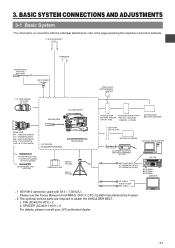
PROTEC) 1.5" VIEW FINDER VF-P115B VF-P116 DV CAMCORDER ZOOM LENS S14 × 7.3B12U(FUJINON) S17 × 6.6BRM(FUJINON) S20 × 6.4B12U(FUJINON...CH-2 LCD BRIGHT FRONT REAR CH-1 CH-2 AUDIO IN AUDIO SELECT CH-1 CH-2 AUTO MANUAL DISPLAY PULL OPEN GY-DV5100 STANDARD PACKAGE TRIPOD BASE FOCUS MANUAL UNIT *1 HZ-FM13 (FUJINON) HZ-FM15 (CANON) ZOOM SERVO UNIT... TP-P300 CARRYING CASE DOLLY TP-P205 ANTON BAUER ANTON BAUER BATTERY BATTERY HOLDER (PRO PAC, MAGNUM, (QR JVC DIGI) TRIMPAC, HYTRON) ANTON BAUER BATTERY CHARGER BATTERY NP-1B TYPE BATTERY CHARGER 4P 4P VC-710 (5m)...
PROTEC) 1.5" VIEW FINDER VF-P115B VF-P116 DV CAMCORDER ZOOM LENS S14 × 7.3B12U(FUJINON) S17 × 6.6BRM(FUJINON) S20 × 6.4B12U(FUJINON...CH-2 LCD BRIGHT FRONT REAR CH-1 CH-2 AUDIO IN AUDIO SELECT CH-1 CH-2 AUTO MANUAL DISPLAY PULL OPEN GY-DV5100 STANDARD PACKAGE TRIPOD BASE FOCUS MANUAL UNIT *1 HZ-FM13 (FUJINON) HZ-FM15 (CANON) ZOOM SERVO UNIT... TP-P300 CARRYING CASE DOLLY TP-P205 ANTON BAUER ANTON BAUER BATTERY BATTERY HOLDER (PRO PAC, MAGNUM, (QR JVC DIGI) TRIMPAC, HYTRON) ANTON BAUER BATTERY CHARGER BATTERY NP-1B TYPE BATTERY CHARGER 4P 4P VC-710 (5m)...
Instruction Manual
Page 35
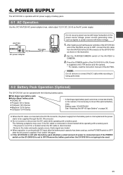
... DV INT DC OUT DC IN TALLY CH-1 CH-2 REAR AUDIO IN Do not use any power source with large fluctuations in the illustration. 2. After making sure that the power switches of the GY-...been used . 35 Power is left with AC power supply or battery pack. 4-1 AC Operation Use the JVC AA-P250 AC power adapter (max. The following battery packs. ■ Flat shape type battery pack ..., 3.5 A) as ripples or power sources with a battery pack. Then switch ON again. ● If the GY-DV5100 is supplied to the VTR section and the camera. * For details, read the instruction manual of the AA...
... DV INT DC OUT DC IN TALLY CH-1 CH-2 REAR AUDIO IN Do not use any power source with large fluctuations in the illustration. 2. After making sure that the power switches of the GY-...been used . 35 Power is left with AC power supply or battery pack. 4-1 AC Operation Use the JVC AA-P250 AC power adapter (max. The following battery packs. ■ Flat shape type battery pack ..., 3.5 A) as ripples or power sources with a battery pack. Then switch ON again. ● If the GY-DV5100 is supplied to the VTR section and the camera. * For details, read the instruction manual of the AA...
Instruction Manual
Page 39
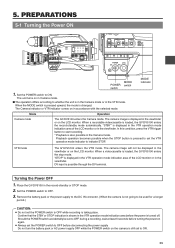
.... When a recordable videocassette is possible through the DV terminal. "STBY" is turned off. VTR mode The GY-DV5100 enters the VTR mode. Set the POWER switch to ON. When the MODE switch is pressed upward, the mode is loaded, the GY-DV5100 enters the stop mode. The camera image ...is displayed in the VTR operation mode indication area of the LCD monitor or in the viewfinder. When a videocassette is changed. Place the GY-DV5100 in accordance with the selected mode. Remove the battery pack or the power supply to indicate STOP. Should the POWER switch accidentally be...
.... When a recordable videocassette is possible through the DV terminal. "STBY" is turned off. VTR mode The GY-DV5100 enters the VTR mode. Set the POWER switch to ON. When the MODE switch is pressed upward, the mode is loaded, the GY-DV5100 enters the stop mode. The camera image ...is displayed in the VTR operation mode indication area of the LCD monitor or in the viewfinder. When a videocassette is changed. Place the GY-DV5100 in accordance with the selected mode. Remove the battery pack or the power supply to indicate STOP. Should the POWER switch accidentally be...

Instruction Manual
Page 40
... MiniDV videocassette Guide Guide After the cassette cover is displayed on the LCD monitor and in POWER OFF mode. ● Use a standard DV videocassette or a MiniDV videocassette. ● Press at the center portion of the cassette back and insert the cassette tape straight into the slot... 5-2 Cassette Loading and Unloading OPEN knob Cassette cover Cassette insertion slot Cassette cover ● A cassette cannot be loaded or unloaded while the GY-DV5100 is being pulled in damage. Set the POWER switch to open the cassette cover. 3. The tape window should face outward and the ...
... MiniDV videocassette Guide Guide After the cassette cover is displayed on the LCD monitor and in POWER OFF mode. ● Use a standard DV videocassette or a MiniDV videocassette. ● Press at the center portion of the cassette back and insert the cassette tape straight into the slot... 5-2 Cassette Loading and Unloading OPEN knob Cassette cover Cassette insertion slot Cassette cover ● A cassette cannot be loaded or unloaded while the GY-DV5100 is being pulled in damage. Set the POWER switch to open the cassette cover. 3. The tape window should face outward and the ...
Instruction Manual
Page 45
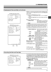
.../CLOCK item on the TOP MENU screen. 2 Select the TIME/DATE item on the Screen TC/UB/CLOCK menu screen --- During DV signal input : The date and time from the DV connector are output. When the DATE REC item on the side section is set to ON. ● DISPLAY MODE item : Sets...
.../CLOCK item on the TOP MENU screen. 2 Select the TIME/DATE item on the Screen TC/UB/CLOCK menu screen --- During DV signal input : The date and time from the DV connector are output. When the DATE REC item on the side section is set to ON. ● DISPLAY MODE item : Sets...

Instruction Manual
Page 46
... is discharged but the date and time and time code data cannot be recorded. ■ How to the GY-DV5100 and an AC outlet or mount a charged battery on the GY-DV5100 to "OFF" or "ON" (charging takes places with the POWER switch set to a power supply, but it is possible to... and time code data are reset. Connect the provided AC adapter AA-P250 to charge AC outlet AA-P250 AC power adapter DC cable PHONES DV INT DC OUT DC IN TALLY CH-1 CH-2 REAR AUDIO IN 1. Leave the equipment in this case, recharge the built-in battery is constantly being...
... is discharged but the date and time and time code data cannot be recorded. ■ How to the GY-DV5100 and an AC outlet or mount a charged battery on the GY-DV5100 to "OFF" or "ON" (charging takes places with the POWER switch set to a power supply, but it is possible to... and time code data are reset. Connect the provided AC adapter AA-P250 to charge AC outlet AA-P250 AC power adapter DC cable PHONES DV INT DC OUT DC IN TALLY CH-1 CH-2 REAR AUDIO IN 1. Leave the equipment in this case, recharge the built-in battery is constantly being...
Instruction Manual
Page 51
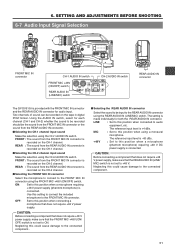
... +48 V power supply. ON: Set to this could cause damage to ON. 6. PRST FREE REC REGEN PHONES DV INT DC OUT DC IN TALLY CH-1 CH-2 REAR AUDIO IN REAR AUDIO IN connector The GY-DV5100 is +4 dBs. Neglecting this position when a microphone requiring +48 V power supply (phantom microphone) is not set...
... +48 V power supply. ON: Set to this could cause damage to ON. 6. PRST FREE REC REGEN PHONES DV INT DC OUT DC IN TALLY CH-1 CH-2 REAR AUDIO IN REAR AUDIO IN connector The GY-DV5100 is +4 dBs. Neglecting this position when a microphone requiring +48 V power supply (phantom microphone) is not set...
Instruction Manual
Page 54
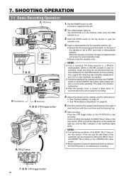
...9679; Power is loaded and the unit enters the record-standby mode. ● Slowly close the cassette cover. MEMO: ● Use a standard DV videocassette or a MiniDV videocassette. (When a DVCAM cassette is used for recording. 5. The CAM indicator lights up. When the cassette is inserted, the... Adjust the camera section settings and the white balance. ☞ See "Camera Settings" on page 47. ☞ See "White Balance Adjustment" on the GY-DV5100 to open the cassette cover. 4. OFF ZEBRA ON SKIN AREA AUTO WHITE ACCU FOCUS VTR AUDIO LEVEL CH-1 5 7. 8. 9. VTR trigger button ...
...9679; Power is loaded and the unit enters the record-standby mode. ● Slowly close the cassette cover. MEMO: ● Use a standard DV videocassette or a MiniDV videocassette. (When a DVCAM cassette is used for recording. 5. The CAM indicator lights up. When the cassette is inserted, the... Adjust the camera section settings and the white balance. ☞ See "Camera Settings" on page 47. ☞ See "White Balance Adjustment" on the GY-DV5100 to open the cassette cover. 4. OFF ZEBRA ON SKIN AREA AUTO WHITE ACCU FOCUS VTR AUDIO LEVEL CH-1 5 7. 8. 9. VTR trigger button ...


