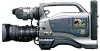
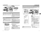
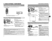
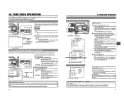
Wired Peer-to-Peer Connections from Streamcorder to Computer
Page 2
...the same network group. In the example above , the network group is 192.168.100. What You Need • GY-DV300 camera with a KA-DV300 or KA-DV350 Network Pack, a GY-DV5000 camera with a KADV5000 Network Pack, or a BR-DV6000 VTR with an SA-DV6000 Network Pack. • A ...Socket Communications EA2900-117 Low Power Ethernet Card for more information. Please consult your owners' manual for either the KA-DV300/350 or KA-DV5000. • A computer with ...
Wireless Peer-to-Peer Connections from Streamcorder to Computer
Page 3
... SET windows, shown below, the following discussion are from a KA-DV300 revision 2.00. What You Need • GY-DV300 camera with a KA-DV300/350 Network Pack, GY-DV5000 camera with a KA-DV5000 Network Pack, or a BR-DV6000 VTR with an SA-DV6000 Network Pack. • A wireless network card (with...-to a different computer. Other revisions of 7 Turn the camera or VTR power ON and wait for the Network Pack initialization sequence to your owners' manual for the Streamcorder. You will be used by the Streamcorder • A computer with a wireless LAN interface, you must be set : • ...
DR-DV5000U DV Video Disk Recorder 44 page instruction manual
Page 12
... manual provides detailed instructions and illustrations. 7) Finally, connect a 6-pin to 4-pin FireWire cable from the 6-pin FireWire port on DRDV5000 marked "DV I/O" to the 4-pin FireWire port on certain JVC GY-DV5000 series camcorders. This final step is necessary on all JVC GYDV500, -550 and -700 series camcorders, but may not be necessary on the rear of the camcorder...
DR-DV5000U DV Video Disk Recorder 44 page instruction manual
Page 29
...(at startup, upon manual connect) and after the track list has been constructed, DR-DV5000 looks at the last... the last frame in GY-DV5000 ends. Use different TC mode when using with DR-DV5000. REGEN Mode - FireStore DR-DV5000 User Guide will clear any...the incoming DV timecode, DR-DV5000 records it. In this mode persists across recording sessions. After a disk is stored in the memory, so this mode, DR-DV5000 does the... REC RUN Mode - Selecting JVC DV5000 or 500/-700 will stop once tape in that particular model. Highlighted mode is the current camcorder after exit. EXT TC Mode...
GY-DV5000U 3-CCD Professional DV Camcorder 92 page instruction manual
Page 1
...JVC product. DV CAMCORDER INTRODUCTION CONTROLS, INDICATORS AND CONNECTORS BASIC SYSTEM CONNECTIONS AND ADJUSTMENTS POWER SUPPLY PREPARATIONS SETTING AND ADJUSTMENTS BEFORE SHOOTING SHOOTING OPERATION GY-DV5000 INSTRUCTIONS PLAYBACK MODE USING EXTERNAL COMPONENTS TIME CODE OPERATION MENU SCREENS FEATURES OF THE CAMERA SECTION OTHERS CAUTION This section of instruction manual...-001A * The illustration shows the GY-DV5000 DV Camcorder with the optional lens, viewfinder, Microphone holder and Microphone attached. This instruction manual is specially edited for service purpose with...
GY-DV5000U 3-CCD Professional DV Camcorder 92 page instruction manual
Page 5
...When storing the GY-DV5000 for a ...sure to set the POWER switch to the service manual page. 2-6 "2.4.3 Cleaning" 7 However, this ...may occur at the periphery of professional video equipment at high levels....viewfinder directly at your nearest JVC-authorized service agent. As ...and audio quality at your nearest JVC-authorized service agent. Block Noise ...1-2 Routine and Periodical Maintenance The GY-DV5000 incorporates precision mechanical parts, which ...these spots are generated by JVC. To prevent wear and...unit against penetration of professional video equipment at the...
GY-DV5000U 3-CCD Professional DV Camcorder 92 page instruction manual
Page 6
...8 For servicing Refer to the service manual page. 1-9 "White blemish derection" ← 1. However, some of the unit in noise caused by JVC. This phenomenon is possible to reach ...condensation forms gradually, the condensation indication may be Used The GY-DV5000 can cause CCD sensor pixels to be Used ● Use JVC's videocassette tapes marked with little humidity and good ventilation ... High temperatures can use cleaning tape produced by dropouts, etc. Standard DV videocassette: LA-DV276, LA-DV186, LADV124 Mini DV videocassette: M-DV63PRO, M-DV60, M-DV30 * Do not use the...
GY-DV5000U 3-CCD Professional DV Camcorder 92 page instruction manual
Page 16
PROTEC) 1.5" VIEW FINDER VF-P115B VF-P116 DV CAMCORDER ZOOM LENS S14 × 7.3B12U(FUJINON) S17 × 6.6BRM(FUJINON) S20 × 6.4B12U(FUJINON)... LCD BRIGHT FRONT REAR CH-1 CH-2 AUDIO INPUT AUDIO SELECT CH-1 CH-2 AUTO MANUAL DISPLAY PULL OPEN GY-DV5000 STANDARD PACKAGE TRIPOD BASE KA-550U FOCUS MANUAL UNIT HZ-FM13 (FUJINON) HZ-FM15 (CANON) ZOOM SERVO UNIT HZ-ZS13B CARRYING ...CHARGER 4P 4P VC-710 (5m) AC AC POWER ADAPTER (BATTERY CHARGER) AA-P250 Non-linear Editing SYSTEM DV VTR IEEE1394 CABLE VC-VDV204(2m)(4P-4P) VC-VDV206(2m)(4P-6P) BR-DV600A BR-DV3000 BR-DV6000...
GY-DV5000U 3-CCD Professional DV Camcorder 92 page instruction manual
Page 18
... the AA-P250. Power is left with the pin on a tripod. 1. Then switch ON again. ● If the GY-DV5000 is supplied to the VTR section and the camera. * For details, read the instruction manual of the AA-P250 to place the camera on the tripod base. 4. Lock lever 3. Therefore, after the DC... DV REAR AUDIO IN DC OUT DC IN TALLY Do not use any impact or vibration should be connected directly to remove the unit from the battery pack is consumed even if the POWER switch on a tripod, any power source with AC power supply or battery pack. 4-1 AC Operation Use the JVC...
GY-DV5000U 3-CCD Professional DV Camcorder 92 page instruction manual
Page 19
...the battery pack has been attached. Use the following battery holder. • Battery holder: Anton-Bauer QRQ27 Detaching the Battery Case From the GY-DV5000 and Attaching The AntonBauer Battery Attaching the Anton-Bauer Battery Holder Anton-Bauer Battery Holder 4. 2. 5. 1. Take care not to OFF before ... 1. Side panel with display AUDIO LEVEL CH-2 LCD BRIGHT FRONT REAR CH-1 CH-2 AUDIO INPUT AUDIO SELECT CH-1 CH-2 AUTO MANUAL DISPLAY PULL OPEN Battery Detaching the Battery Pack ■ While pushing the release lever, slide the battery pack toward the side panel...
GY-DV5000U 3-CCD Professional DV Camcorder 92 page instruction manual
Page 20
... MANUAL DISPLAY PULL OPEN LOW VOLTAGE 10.5V TALLY lamp Battery lamp Viewfinder LOW VOLTAGE 10.5V REC BATT ALARM When the remaining battery power is nearly exhausted, the following warnings will not be stored in the viewfinder. Mode Camera mode Operation The GY-DV5000 ... is reduced by repeating incomplete recharging, or recharging without discharging, once discharge the battery pack completely, then recharge it . VTR mode The GY-DV5000 enters the VTR playback mode. "STOP" is displayed in the viewfinder. 4. POWER SUPPLY 4-2 Battery Pack Operation (Optional) (Cont'd) REMAINING...
GY-DV5000U 3-CCD Professional DV Camcorder 92 page instruction manual
Page 24
...GY-DV5000 even if the bulit-in the battery case on ). Set the POWER switch on the LCD/VF (1/2) menu screen. ☞ See page 73. ● When ASPECT RATIO is set to charge AC outlet AA-P250 AC power adapter DC cable PHONES DV...A. BAL] (Auto White Balance) switch: Set to OFF (1/60). VF 4. 5. However, it gradually discharges while the GY-DV5000 is discharged but the date and time and time code data cannot be displayed in the viewfinder or LCD by setting the... CH-1 CH-2 AUDIO INPUT AUDIO SELECT CH-1 CH-2 AUTO MANUAL DISPLAY PULL OPEN 1. If battery pack is always 0 dB.
GY-DV5000U 3-CCD Professional DV Camcorder 92 page instruction manual
Page 25
... star chart. 1. Repeat steps 4. Adjust the position and angle of the GY-DV5000. 2. Set the COLOR BARS/CAMERA/AUTO KNEE switch to BARS to the standard screen (R, G and B will all appear). 8. Set the lens to M (Manual). 3. about three times for fine adjustment until the lens is no difference ... 3. 4. 6. 5. Open the iris by selecting the desired size with the BRIGHT and CONT controls. Use the monitor's brightness control to M (Manual). 2. 6. View the same subject and adjust the back focus ring for the first time or when focusing is clearly visible. 3.
GY-DV5000U 3-CCD Professional DV Camcorder 92 page instruction manual
Page 26
...-adjust the white balance when the main light source illuminating the subject changes. REGEN FREE REC PRST PHONES DV REAR AUDIO IN DC OUT DC IN TALLY REAR AUDIO IN connector The GY-DV5000 is not enough white color on the CH-1 channel. ■ Selecting the CH-2 channel input sound... IN connector is recorded on the light source, it contains only a single color or not enough white color. ● The accuracy of the manual white balance. ● When the power is connected. In this case, change the color temperature conversion filter setting to fill the screen with the...
GY-DV5000U 3-CCD Professional DV Camcorder 92 page instruction manual
Page 28
... CH-2 LCD BRIGHT FRONT REAR CH-1 CH-2 AUDIO INPUT AUDIO SELECT CH-1 CH-2 AUTO MANUAL DISPLAY PULL OPEN POWER VTR ON OFF 1. 7, 8, 9, MODE VTR CAM 2. 6. VTR trigger button 1. The GY-DV5000 is in the Camera mode when the CAM indicator is on page 48. 6. When the cassette...menu screen. 8. TALLY lamp OFF ZEBRA ON SKIN AREA AUTO WHITE ACCU FOCUS VTR AUDIO LEVELE CH-1 5 7. 8. 9. MEMO: ● Use a standard DV videocassette or a MiniDV videocassette. (When a DVCAM cassette is not going to take out the videocassette. ■ When the power should be guaranteed if a ...
GY-DV5000U 3-CCD Professional DV Camcorder 92 page instruction manual
Page 29
..., press the VTR trigger button. ● The drum starts rotating, and recording starts after playback. * This function does not work when the GY-DV5000 is finished, the tape returns to the position at maximum. ● Pressing the VTR trigger button during playback will appear if the error rate ...VTR CAM POWER VTR ON OFF OPEN CH-1 AUDIO LEVEL CH-2 LCD BRIGHT FRONT REAR CH-1 CH-2 AUDIO INPUT AUDIO SELECT CH-1 CH-2 AUTO MANUAL DISPLAY PULL OPEN EDITSEARCH ATUS EDIT SEARCH + button EDIT SEARCH - 7. button is rewound and played back for a scene when you want to search...
GY-DV5000U 3-CCD Professional DV Camcorder 92 page instruction manual
Page 30
... STILL MODE VTR CAM Still button PLAY button STOP button POWER switch MODE switch MEMO: ● The GY-DV5000 can be viewed in the playback image. ● This unit does not allow manual tracking adjustment. ● When playing back a tape that was recorded on the VTR indicator. ●... mode has continued for the date and time or time code on the tape can play back the following three types of videocassettes: • DV videocassette • MiniDV videocassette • DVCAM videocassette ● Tapes recorded in the LP mode cannot be selected during playback. ● Following...
GY-DV5000U 3-CCD Professional DV Camcorder 92 page instruction manual
Page 31
...CH-2 AUTO MANUAL DISPLAY PULL OPEN BLANK SEARCH REW STOP FF PLAY STILL REW button FF button 8-2 Fast-Forward, Rewind ■ Press the FF button in the VTR mode. (VTR indicator: On) 1. The GY-DV5000 records audio on the tape, such as the end of DV input.) When the GY-DV5000 is shown.)... the cursor ( ) with the AUDIO SELECT item, and then press the SHUTTER dial. ● The setting area of a tape that the GY-DV5000 is confirmed. 6. Press the STATUS button for fast forwarding and rewinding may freeze during fast forwarding or rewinding, the tape speed decelerates to protect...
GY-DV5000U 3-CCD Professional DV Camcorder 92 page instruction manual
Page 32
...-1 AUDIO LEVEL CH-2 LCD BRIGHT FRONT REAR CH-1 CH-2 AUDIO INPUT AUDIO SELECT CH-1 CH-2 AUTO MANUAL DISPLAY PULL OPEN DV cable Signal flow Backup unit Connections Use the GY-DV5000 as Playback Unit (Dubbing to the unit used component, it may not be dubbed to turn on the... ■ Backup unit ● Place in accordance with start playback. 6. Connect the units with DV Connector DV connector When Using the GY-DV5000 as the master unit. Rear section of recording on the GY-DV5000 to STOP or REC PAUSE status. Press the MODE switch upward to . Start and stop of ...
GY-DV5000U 3-CCD Professional DV Camcorder 92 page instruction manual
Page 33
TIME CODE OPERATION The GY-DV5000 records SMPTE-standard time codes and user's bits. REGEN FREE REC PRST... OPEN CH-1 AUDIO LEVEL CH-2 LCD BRIGHT FRONT REAR CH-1 CH-2 AUDIO INPUT AUDIO SELECT CH-1 CH-2 AUTO MANUAL DISPLAY PULL OPEN LCD BRIGHT DISPLAY CH-1 AUDIO LEVEL CH-2 MONITOR SELECT CH-1 MIX CH-2 AUDIO INPUT FRONT REAR LINE...OPEN CH-1 AUDIO LEVEL CH-2 LCD BRIGHT FRONT REAR CH-1 CH-2 AUDIO INPUT AUDIO SELECT CH-1 CH-2 AUTO MANUAL DISPLAY PULL OPEN COUNTER switch LCD BRIGHT DISPLAY CH-1 AUDIO LEVEL CH-2 MONITOR SELECT CH-1 MIX CH-2 AUDIO ...