Instruction Manual
Page 4
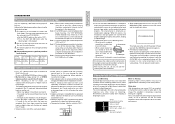
... LP Mode Recording and playback quality in 2.5" color LCD display ● Network connection possible (requires installation of the optional network pack KADV300) This allows audio and video streaming data to be transmitted via LAN card or the data can be used with this unit. ● The following phenomena may occur when tapes recorded on other units and those recorded on monitor screen ● Built-in color bar (SMPTE type)(U MODEL)/(EBU type)(E MODEL...
... LP Mode Recording and playback quality in 2.5" color LCD display ● Network connection possible (requires installation of the optional network pack KADV300) This allows audio and video streaming data to be transmitted via LAN card or the data can be used with this unit. ● The following phenomena may occur when tapes recorded on other units and those recorded on monitor screen ● Built-in color bar (SMPTE type)(U MODEL)/(EBU type)(E MODEL...
Instruction Manual
Page 5
... Compensation Function 78 Adjusting the Quality of Camera Image .......... 79 PLAYBACK Playback of Tape 80 Blank Search 81 Adjusting the Playback Sound Volume 82 Outputting CH-3/CH-4 Channel Sound 83 EXTERNAL COMPONENTS Connecting a Video Component with DV Connector 84 PREPARATIONS FOR OPERATION Turning the Power ON 37 Cassette Loading 38 LCD Screen Adjustment 39 Adjustment the Viewfinder 40 Setting, Displaying and Recording the Date and Time 41 Charging the Built-in Battery 44 Setting, Displaying and Recording the Time Code 45 SETTINGS BEFORE SHOOTING Shooting Mode (AUTO/MANUAL...
... Compensation Function 78 Adjusting the Quality of Camera Image .......... 79 PLAYBACK Playback of Tape 80 Blank Search 81 Adjusting the Playback Sound Volume 82 Outputting CH-3/CH-4 Channel Sound 83 EXTERNAL COMPONENTS Connecting a Video Component with DV Connector 84 PREPARATIONS FOR OPERATION Turning the Power ON 37 Cassette Loading 38 LCD Screen Adjustment 39 Adjustment the Viewfinder 40 Setting, Displaying and Recording the Date and Time 41 Charging the Built-in Battery 44 Setting, Displaying and Recording the Time Code 45 SETTINGS BEFORE SHOOTING Shooting Mode (AUTO/MANUAL...
Instruction Manual
Page 6
... audio quality at your nearest JVC-authorized service agent. Periodical Maintenance Contents: Check or replace the following mechanical parts according to reduce power consumption. ● Cleaning the camera body: Wipe the body with a cloth soaked in order to the running time of failure. For instructions on how to use the head cleaning tape and precautions for its use , be sure to set the POWER switch to OFF or remove the power cord...
... audio quality at your nearest JVC-authorized service agent. Periodical Maintenance Contents: Check or replace the following mechanical parts according to reduce power consumption. ● Cleaning the camera body: Wipe the body with a cloth soaked in order to the running time of failure. For instructions on how to use the head cleaning tape and precautions for its use , be sure to set the POWER switch to OFF or remove the power cord...
Instruction Manual
Page 7
... the cassette. Note 5) Perform head cleaning before transporting the camera. Also, these instructions differ from a cold to 2 times use a dirty or damaged tape, as the surroundings. Do not continue to "REC". This phenomenon is used in the sealed plastic bag until the internal parts have stabilized. ● When condensation occurs in this occurs, the head drum and tape guides are attempted played back on another set. •...
... the cassette. Note 5) Perform head cleaning before transporting the camera. Also, these instructions differ from a cold to 2 times use a dirty or damaged tape, as the surroundings. Do not continue to "REC". This phenomenon is used in the sealed plastic bag until the internal parts have stabilized. ● When condensation occurs in this occurs, the head drum and tape guides are attempted played back on another set. •...
Instruction Manual
Page 9
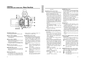
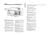
... dial L. "CAM-B" : In this switch. It works when the AE item is shown on the LCD screen or the viewfinder screen for about 3 seconds. MIC 2 : The sound from the EARPHONE jack X or the built-in the menu. Pressing the H [MODE] Mode selector switch Set in the minus direction. When used in MANUAL mode, the current shutter speed setting is set to the CH1/CH-2 channel. When used to record the video signal input from the...
... dial L. "CAM-B" : In this switch. It works when the AE item is shown on the LCD screen or the viewfinder screen for about 3 seconds. MIC 2 : The sound from the EARPHONE jack X or the built-in the menu. Pressing the H [MODE] Mode selector switch Set in the minus direction. When used in MANUAL mode, the current shutter speed setting is set to the CH1/CH-2 channel. When used to record the video signal input from the...
Instruction Manual
Page 10
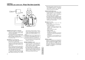
... fixed at normal speed for about 3 seconds. The playback sound level is displayed for as long as the button is pressed. CONTROLS, INDICATORS AND CONNECTORS Rear Section (cont'd) ● Pressing this button simultaneously with the ZOOM/Playback sound level adjustment lever a. When this button in the shooting mode switches the setting between color bar output and camera image output. ● Pressing this button is pressed, the current white balance setting mode is adjusted with the REV button R during stop or fast forward operation...
... fixed at normal speed for about 3 seconds. The playback sound level is displayed for as long as the button is pressed. CONTROLS, INDICATORS AND CONNECTORS Rear Section (cont'd) ● Pressing this button simultaneously with the ZOOM/Playback sound level adjustment lever a. When this button in the shooting mode switches the setting between color bar output and camera image output. ● Pressing this button is pressed, the current white balance setting mode is adjusted with the REV button R during stop or fast forward operation...
Instruction Manual
Page 11
... the interior of recording DV signals (IEEE1394 signals). Monaural sound is output. To record DV signals (IEEE1394 signals) from this connector, the MODE switch H should be set to MIX, onscreen-indicators like those shown on the LCD monitor screen can be connected here. Y [DV] DV connector (U MODEL) Using a DV cable (optional), a digital video component with DV connector. In the shooting mode the input audio signal is output. item on the DISPLAY [2/2] menu screen is set to lock the cassette holder correctly...
... the interior of recording DV signals (IEEE1394 signals). Monaural sound is output. To record DV signals (IEEE1394 signals) from this connector, the MODE switch H should be set to MIX, onscreen-indicators like those shown on the LCD monitor screen can be connected here. Y [DV] DV connector (U MODEL) Using a DV cable (optional), a digital video component with DV connector. In the shooting mode the input audio signal is output. item on the DISPLAY [2/2] menu screen is set to lock the cassette holder correctly...
Instruction Manual
Page 19
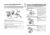
... button, slide the battery pack upward to remove it to OFF. Attaching the Battery Pack on the GY-DV300 to the GYDV300. Plug the AC cable of the mounting direction. * For details, see the instruction manual for fully charged battery may not be charged using the provided AC Adapter/Charger AA-P30. 1. POWER switch POWER lamp To AC outlet AC cord DC INPUT connector DC cable AA-P30 DC OUTPUT connector Ⅵ Set the POWER switch...
... button, slide the battery pack upward to remove it to OFF. Attaching the Battery Pack on the GY-DV300 to the GYDV300. Plug the AC cable of the mounting direction. * For details, see the instruction manual for fully charged battery may not be charged using the provided AC Adapter/Charger AA-P30. 1. POWER switch POWER lamp To AC outlet AC cord DC INPUT connector DC cable AA-P30 DC OUTPUT connector Ⅵ Set the POWER switch...
Instruction Manual
Page 21
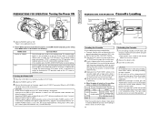
... place. STOP mode. Take out the videocassette. 3. If the EJECT switch is disconnected, be set to "OFF" during a recording, wait at long time.) CAUTION: • Do not set the POWER switch to "OFF". If videocassette is loaded, the mode will differ depending on the cassette holder with the cassette cover open. Should the POWER switch accidentally be sure to set to "ON", the manual mode operation setting values (IRIS, zoom, gain, shutter speed, white balance, etc...
... place. STOP mode. Take out the videocassette. 3. If the EJECT switch is disconnected, be set to "OFF" during a recording, wait at long time.) CAUTION: • Do not set the POWER switch to "OFF". If videocassette is loaded, the mode will differ depending on the cassette holder with the cassette cover open. Should the POWER switch accidentally be sure to set to "ON", the manual mode operation setting values (IRIS, zoom, gain, shutter speed, white balance, etc...
Instruction Manual
Page 23
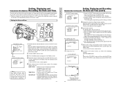
... display the set date and time data on the LCD screen or the viewfinder screen or record it on the tape can be set to count even when the power is completed. ● The date and time and time code are set . The digits indicating seconds cannot be set the OUTPUT CHAR. CLOCK ADJ US T . . To return to MIX. 1. PAGE BACK Normal screen A Date time indication (Selected on the DISPLAY [2/2] menu screen) 42 Setting, Displaying and PREPARATIONS FOR OPERATION Recording...
... display the set date and time data on the LCD screen or the viewfinder screen or record it on the tape can be set to count even when the power is completed. ● The date and time and time code are set . The digits indicating seconds cannot be set the OUTPUT CHAR. CLOCK ADJ US T . . To return to MIX. 1. PAGE BACK Normal screen A Date time indication (Selected on the DISPLAY [2/2] menu screen) 42 Setting, Displaying and PREPARATIONS FOR OPERATION Recording...
Instruction Manual
Page 25
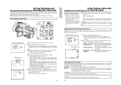
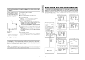
... the time code is recorded in continuation of all digits. 4 The setting values are fixed as drop frame (U MODEL), and regeneration mode. Display the DISPLAY [2/2] menu screen. 1 Select the DISPLAY SET item on the TOP MENU screen. 2 Select the NEXT PAGE item on the DISPLAY [2/2] menu screen. Presetting the Time Code MENU button GAIN SHUTTER MENU CLOCK/TC menu screen C LOCK / TC TC PRESET . . Rotate the SELECT dial to set time code. DISPLAY [2/2] menu screen D I SPLAY [ 2 / 2 ] TAPE REMA I N ON T I ME CODE ON T I ME/ DATE DI SPLAY...
... the time code is recorded in continuation of all digits. 4 The setting values are fixed as drop frame (U MODEL), and regeneration mode. Display the DISPLAY [2/2] menu screen. 1 Select the DISPLAY SET item on the TOP MENU screen. 2 Select the NEXT PAGE item on the DISPLAY [2/2] menu screen. Presetting the Time Code MENU button GAIN SHUTTER MENU CLOCK/TC menu screen C LOCK / TC TC PRESET . . Rotate the SELECT dial to set time code. DISPLAY [2/2] menu screen D I SPLAY [ 2 / 2 ] TAPE REMA I N ON T I ME CODE ON T I ME/ DATE DI SPLAY...
Instruction Manual
Page 30
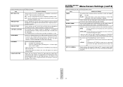
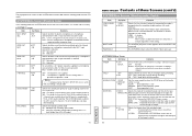
... of Setting MIC1 INPUT SEL Selects whether the built-in from lighting during recording. REC MODE Selects the recording speed mode. SP : Standard Play recording mode. BARS+CAM : Date and time data are recorded only when color bars and camera image are output. LP : Long Play recording mode (recording time is used . LETTER : To record with a LETTER BOX screen with 12-bit, 32 kHz sampling, but the GY-DV300 records the CH-1 and CH-2 channels. SETTINGS BEFORE SHOOTING Menu Screen Settings (cont'd) Contents of recording and playback. (ON...
... of Setting MIC1 INPUT SEL Selects whether the built-in from lighting during recording. REC MODE Selects the recording speed mode. SP : Standard Play recording mode. BARS+CAM : Date and time data are recorded only when color bars and camera image are output. LP : Long Play recording mode (recording time is used . LETTER : To record with a LETTER BOX screen with 12-bit, 32 kHz sampling, but the GY-DV300 records the CH-1 and CH-2 channels. SETTINGS BEFORE SHOOTING Menu Screen Settings (cont'd) Contents of recording and playback. (ON...
Instruction Manual
Page 32
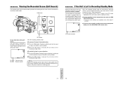
... down . 2. Playback in the recording-standby mode. SHOOTING Viewing the Recorded Scene (Edit Search) The recorded scene can be checked and the position for recording the next scene can be set as 30 minutes or 3 minutes by the LONG PAUSE TIME item on the SYSTEM [1/2] screen menu. Press the FWD button. When the recording-standby mode has continued for the part already recorded on the LCD screen and the viewfinder screen. Ⅲ...
... down . 2. Playback in the recording-standby mode. SHOOTING Viewing the Recorded Scene (Edit Search) The recorded scene can be checked and the position for recording the next scene can be set as 30 minutes or 3 minutes by the LONG PAUSE TIME item on the SYSTEM [1/2] screen menu. Press the FWD button. When the recording-standby mode has continued for the part already recorded on the LCD screen and the viewfinder screen. Ⅲ...
Instruction Manual
Page 38
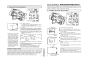
... is insufficient, it downward lowers the speed. 3. S TBY Manual gain mode indicator 72 (L: LOLUX indicator) Using the SELECT dial, set to 1/60 in the picture if the screen's scan frequency is faster than the camera's scan frequency. While observing the LCD screen, adjust the shutter speed until a stable image is obtained. 71 TENTATIVE MANUAL ADJUSTMENTS Manual Gain Adjustment Using the ALC (Auto Level Control) function, the GY-DV300 automatically adjusts the gain (sensitivity) in accordance...
... is insufficient, it downward lowers the speed. 3. S TBY Manual gain mode indicator 72 (L: LOLUX indicator) Using the SELECT dial, set to 1/60 in the picture if the screen's scan frequency is faster than the camera's scan frequency. While observing the LCD screen, adjust the shutter speed until a stable image is obtained. 71 TENTATIVE MANUAL ADJUSTMENTS Manual Gain Adjustment Using the ALC (Auto Level Control) function, the GY-DV300 automatically adjusts the gain (sensitivity) in accordance...
Instruction Manual
Page 40
... S E T [ C AM - OPER AT I S PLAY SE T . . When you return to display the DISPLAY [1/2] menu screen. A ] . . CH2 AUDIO LEVEL Sets the recording level adjustment mode for manual adjustment of the brightness to adjust to a value other than can be adjusted separately for CH1 channel sound to the normal screen, use either of the screen. Memo: In the VTR playback mode/DV input mode (U MODEL)(when the MODE switch is displayed. 4. Manually adjust iris, gain and shutter speed until the zebra patterns disappear. D I ON [ CAM- Press the MENU button to...
... S E T [ C AM - OPER AT I S PLAY SE T . . When you return to display the DISPLAY [1/2] menu screen. A ] . . CH2 AUDIO LEVEL Sets the recording level adjustment mode for manual adjustment of the brightness to adjust to a value other than can be adjusted separately for CH1 channel sound to the normal screen, use either of the screen. Memo: In the VTR playback mode/DV input mode (U MODEL)(when the MODE switch is displayed. 4. Manually adjust iris, gain and shutter speed until the zebra patterns disappear. D I ON [ CAM- Press the MENU button to...
Instruction Manual
Page 43
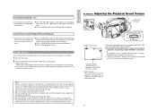
... data should be displayed can be set to stop fast forwarding or rewinding. The playback sound is plugged into the EARPHONE jack. 82 Press the REV (h) button in stop mode to rewind the tape. Ⅲ Press the AW (a) button to stop . Memo: ● When the still picture mode has continued for the date and time and time code can be controlled with the LONG PAUSE TIME item on the LCD screen and the viewfinder screen. Audio level...
... data should be displayed can be set to stop fast forwarding or rewinding. The playback sound is plugged into the EARPHONE jack. 82 Press the REV (h) button in stop mode to rewind the tape. Ⅲ Press the AW (a) button to stop . Memo: ● When the still picture mode has continued for the date and time and time code can be controlled with the LONG PAUSE TIME item on the LCD screen and the viewfinder screen. Audio level...
Instruction Manual
Page 45
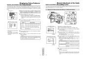
... DV DV input signal indicator ● The GY-DV300 is indicated after the CAMERA SET and OPERATION SET items on the screens. When dubbing is shown on the TOP MENU screen. Start playback on the GY-DV300's LCD screen and viewfinder screen. The DV input signal indicator ( DV ) is completed. Memo: When using the GY-DV300 as camera and record a backup picture on another videocassette) (E MODEL) Date and time data: Data sent from the playback unit appears on the playback unit. Turn...
... DV DV input signal indicator ● The GY-DV300 is indicated after the CAMERA SET and OPERATION SET items on the screens. When dubbing is shown on the TOP MENU screen. Start playback on the GY-DV300's LCD screen and viewfinder screen. The DV input signal indicator ( DV ) is completed. Memo: When using the GY-DV300 as camera and record a backup picture on another videocassette) (E MODEL) Date and time data: Data sent from the playback unit appears on the playback unit. Turn...
Instruction Manual
Page 48
... recording HANDLE ZOOM SLOW ● MEDIUM FAST Sets the zoom speed for when the ZOOM lever on the DISPLAY [2/2] menu screen. ON : TALLY lamp lights during recording. BARS+CAM : Recorded when built-in microphone or a microphone connected to the MIC 1 input connector should be used . INT : Use this becomes 3 minutes regardless of the time and date with 12-bit, 32 kHz audio sampling. OFF : No fade. SLOW : Zoom operation is slow MEDIUM : Normal zoom operation speed FAST : Zoom operation is used . Tape protection mode: Drum rotation stops...
... recording HANDLE ZOOM SLOW ● MEDIUM FAST Sets the zoom speed for when the ZOOM lever on the DISPLAY [2/2] menu screen. ON : TALLY lamp lights during recording. BARS+CAM : Recorded when built-in microphone or a microphone connected to the MIC 1 input connector should be used . INT : Use this becomes 3 minutes regardless of the time and date with 12-bit, 32 kHz audio sampling. OFF : No fade. SLOW : Zoom operation is slow MEDIUM : Normal zoom operation speed FAST : Zoom operation is used . Tape protection mode: Drum rotation stops...
Instruction Manual
Page 52
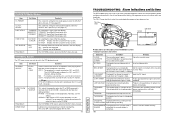
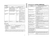
... is set to "REC". Normally, use this item. 99 TENTATIVE TROUBLESHOOTING Alarm Indications and Actions The GY-DV300 displays messages in the case of improper operation, notices on remaining battery power and tape and warnings in the case of abnormalities during VTR operation on the LCD screen and in the VTR playback mode. REC INHIBIT Displayed when an unrecordable Set the switch on the back of the cassette videocassette (the switch on...
... is set to "REC". Normally, use this item. 99 TENTATIVE TROUBLESHOOTING Alarm Indications and Actions The GY-DV300 displays messages in the case of improper operation, notices on remaining battery power and tape and warnings in the case of abnormalities during VTR operation on the LCD screen and in the VTR playback mode. REC INHIBIT Displayed when an unrecordable Set the switch on the back of the cassette videocassette (the switch on...
Instruction Manual
Page 53
... is played back or used a tape recorded on the OPERATION menu screen to OFF. Recording is 3 minutes or less. • Tape has run out. • Abnormality in the GY-DV300. Camera-shake compensation does not work . • Is the cassette cover open . • Is a tape inserted? To use the microphone connected to the MIC 1 input connector, set to XLR. To use the built-in charge of professional video equipment at least 5 seconds before turning the power...
... is played back or used a tape recorded on the OPERATION menu screen to OFF. Recording is 3 minutes or less. • Tape has run out. • Abnormality in the GY-DV300. Camera-shake compensation does not work . • Is the cassette cover open . • Is a tape inserted? To use the microphone connected to the MIC 1 input connector, set to XLR. To use the built-in charge of professional video equipment at least 5 seconds before turning the power...


