
Design Guide
Page 2
...or characteristics of others. Copyright © 2002 Intel Corporation 2 Intel® E7500 MCH Thermal and Mechanical Design Guidelines Intel reserves these for future definition and shall have an ordering number and are trademarks or registered trademarks of Intel Corporation or its subsidiaries in the United States ...to specifications and product descriptions at any time, without notice. The Intel® E7500 chipset MCH may contain design defects or errors known as errata which have no liability whatsoever, and Intel disclaims any express or implied warranty, relating to sale and/or ...
...or characteristics of others. Copyright © 2002 Intel Corporation 2 Intel® E7500 MCH Thermal and Mechanical Design Guidelines Intel reserves these for future definition and shall have an ordering number and are trademarks or registered trademarks of Intel Corporation or its subsidiaries in the United States ...to specifications and product descriptions at any time, without notice. The Intel® E7500 chipset MCH may contain design defects or errors known as errata which have no liability whatsoever, and Intel disclaims any express or implied warranty, relating to sale and/or ...
Design Guide
Page 3
... 27 6.3.6 Clip Retention Anchors 28 6.3.7 Board Level Component Keep-out Dimensions 28 6.4 Reliability Requirements 30 Appendix A: Thermal Solution Component Suppliers 31 Appendix B: Mechanical Drawings...33 Intel® E7500 MCH Thermal and Mechanical Design Guidelines 3
... 27 6.3.6 Clip Retention Anchors 28 6.3.7 Board Level Component Keep-out Dimensions 28 6.4 Reliability Requirements 30 Appendix A: Thermal Solution Component Suppliers 31 Appendix B: Mechanical Drawings...33 Intel® E7500 MCH Thermal and Mechanical Design Guidelines 3
Design Guide
Page 4
.... Retention Mechanism Component Keep-out Zones 29 Figure 18. Thermal Solution Decision Flowchart 20 Figure 8. R Figures Figure 1. Intel® E7500 MCH Package Dimensions (Side View 11 Figure 3. Extruded Heatsinks 31 Table 5. Interface Materials 32 Table 6. Preferred Heatsink Orientation...Assembly (Side View 24 Figure 11. Heatsink Retention Mechanism Layout 28 Figure 17. Intel® MCH Heatsink Assembly 34 Figure 19. Attach Hardware 32 4 Intel® E7500 MCH Thermal and Mechanical Design Guidelines Complete Thermal Solution Kits 31 Table 4. Extruded Heatsink...
.... Retention Mechanism Component Keep-out Zones 29 Figure 18. Thermal Solution Decision Flowchart 20 Figure 8. R Figures Figure 1. Intel® E7500 MCH Package Dimensions (Side View 11 Figure 3. Extruded Heatsinks 31 Table 5. Interface Materials 32 Table 6. Preferred Heatsink Orientation...Assembly (Side View 24 Figure 11. Heatsink Retention Mechanism Layout 28 Figure 17. Intel® MCH Heatsink Assembly 34 Figure 19. Attach Hardware 32 4 Intel® E7500 MCH Thermal and Mechanical Design Guidelines Complete Thermal Solution Kits 31 Table 4. Extruded Heatsink...
Design Guide
Page 5
Description Date February 2002 Intel® E7500 MCH Thermal and Mechanical Design Guidelines 5 R Revision History Revision Number -001 Initial Release.
Description Date February 2002 Intel® E7500 MCH Thermal and Mechanical Design Guidelines 5 R Revision History Revision Number -001 Initial Release.

Design Guide
Page 6
R This page is intentionally left blank. 6 Intel® E7500 MCH Thermal and Mechanical Design Guidelines
R This page is intentionally left blank. 6 Intel® E7500 MCH Thermal and Mechanical Design Guidelines
Design Guide
Page 7
... the P64H2, refer to ensure that the temperatures of the component. Introduction R 1 Introduction As the complexity of the Intel® E7500 chipset MCH and describe a reference thermal solution. Temperatures exceeding the maximum operating limits may be varied to provide an understanding... of the operating limits of computer systems increases, so do the power dissipation requirements. Intel® E7500 MCH Thermal and Mechanical Design Guidelines 7 The objective of thermal management is to the respective component datasheet. The simplest...
... the P64H2, refer to ensure that the temperatures of the component. Introduction R 1 Introduction As the complexity of the Intel® E7500 chipset MCH and describe a reference thermal solution. Temperatures exceeding the maximum operating limits may be varied to provide an understanding... of the operating limits of computer systems increases, so do the power dissipation requirements. Intel® E7500 MCH Thermal and Mechanical Design Guidelines 7 The objective of thermal management is to the respective component datasheet. The simplest...
Design Guide
Page 8
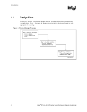
Thermal Reference - Software Users Guide Therm_Design_Proc 8 Intel® E7500 MCH Thermal and Mechanical Design Guidelines Thermal Models - Figure 1 illustrates the design process implicit to the system designer. Thermal Model Users Guide Step 2: Heatsink Selection - ...
Thermal Reference - Software Users Guide Therm_Design_Proc 8 Intel® E7500 MCH Thermal and Mechanical Design Guidelines Thermal Models - Figure 1 illustrates the design process implicit to the system designer. Thermal Model Users Guide Step 2: Heatsink Selection - ...
Design Guide
Page 9
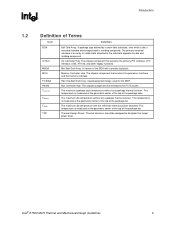
... contains the primary PCI interface, LPC interface, USB, ATA-33, and other legacy functions. The maximum package case temperature without any package thermal solution. Intel® E7500 MCH Thermal and Mechanical Design Guidelines 9 Thermal solutions should be designed to the substrate opposite the die and molding compound. The primary electrical interface is...
... contains the primary PCI interface, LPC interface, USB, ATA-33, and other legacy functions. The maximum package case temperature without any package thermal solution. Intel® E7500 MCH Thermal and Mechanical Design Guidelines 9 Thermal solutions should be designed to the substrate opposite the die and molding compound. The primary electrical interface is...
Design Guide
Page 10
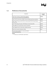
...; PCI/PCI-X 64-bit Hub 2 (P64H2) Thermal and Mechanical Design Guidelines Intel® Xeon™ Processor with 512 KB L2 Cache and Intel® E7500 Chipset Platform Design Guide Intel® E7500 Chipset Datasheet: E7500 Memory Controller Hub (MCH) Intel® 82801CA I/O Controller Hub 3 (ICH3-S) Datasheet Intel® 82870P2 PCI/PCI-X 64-bit Hub 2 (P64H2) Datasheet BGA/OLGA...
...; PCI/PCI-X 64-bit Hub 2 (P64H2) Thermal and Mechanical Design Guidelines Intel® Xeon™ Processor with 512 KB L2 Cache and Intel® E7500 Chipset Platform Design Guide Intel® E7500 Chipset Datasheet: E7500 Memory Controller Hub (MCH) Intel® 82801CA I/O Controller Hub 3 (ICH3-S) Datasheet Intel® 82870P2 PCI/PCI-X 64-bit Hub 2 (P64H2) Datasheet BGA/OLGA...

Design Guide
Page 11
... Thermal and Mechanical Design Guidelines 11 Package_Dimensions_Side NOTES: 1. All dimensions and tolerances conform to the Intel® 82801CA I/O Controller Hub 3 (ICH3-S) Datasheet. For information on the ICH3-S package, refer to ANSI Y14.5M-1982. Intel® E7500 MCH Package Dimensions (Side View) 1.940 ± 0.150 mm Die Substrate 1.10 ± 0.10 mm 0.60...
... Thermal and Mechanical Design Guidelines 11 Package_Dimensions_Side NOTES: 1. All dimensions and tolerances conform to the Intel® 82801CA I/O Controller Hub 3 (ICH3-S) Datasheet. For information on the ICH3-S package, refer to ANSI Y14.5M-1982. Intel® E7500 MCH Package Dimensions (Side View) 1.940 ± 0.150 mm Die Substrate 1.10 ± 0.10 mm 0.60...
Design Guide
Page 12
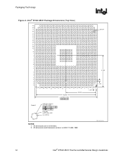
All dimensions are in millimeters. 2. All dimensions and tolerances conform to ANSI Y14.5M-1982. Packaging Technology R Figure 3. MCH_Pkg_TopView 12 Intel® E7500 MCH Thermal and Mechanical Design Guidelines Intel® E7500 MCH Package Dimensions (Top View) AN AM AL Detail A AK AJ AH AG AF AE AD AC AB AA Y W V U T R P N M L K J 21.250 H G F E E C B 1.270 A 33...
All dimensions are in millimeters. 2. All dimensions and tolerances conform to ANSI Y14.5M-1982. Packaging Technology R Figure 3. MCH_Pkg_TopView 12 Intel® E7500 MCH Thermal and Mechanical Design Guidelines Intel® E7500 MCH Package Dimensions (Top View) AN AM AL Detail A AK AJ AH AG AF AE AD AC AB AA Y W V U T R P N M L K J 21.250 H G F E E C B 1.270 A 33...
Design Guide
Page 13
Intel® E7500 MCH Thermal and Mechanical Design Guidelines 13 Contact your Intel Field Sales representative to aid system designers in simulating, analyzing, and optimizing their thermal solutions in an integrated systemlevel environment. The models are for use with the commercially available Computational Fluid Dynamics (CFD)-based thermal analysis tool "FLOTHERM*" (version 3.1 or higher) by Flomerics* Inc. Thermal Simulation R 3 Thermal Simulation Intel provides thermal simulation models of the MCH and associated user's guides to order the thermal models and user's guides.
Intel® E7500 MCH Thermal and Mechanical Design Guidelines 13 Contact your Intel Field Sales representative to aid system designers in simulating, analyzing, and optimizing their thermal solutions in an integrated systemlevel environment. The models are for use with the commercially available Computational Fluid Dynamics (CFD)-based thermal analysis tool "FLOTHERM*" (version 3.1 or higher) by Flomerics* Inc. Thermal Simulation R 3 Thermal Simulation Intel provides thermal simulation models of the MCH and associated user's guides to order the thermal models and user's guides.

Design Guide
Page 14
Thermal Simulation R This page is intentionally left blank. 14 Intel® E7500 MCH Thermal and Mechanical Design Guidelines
Thermal Simulation R This page is intentionally left blank. 14 Intel® E7500 MCH Thermal and Mechanical Design Guidelines
Design Guide
Page 15
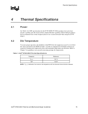
Intel recommends that system designers plan for one or more heatsinks when using the E7500 chipset. 4.2 Die Temperature To ensure proper operation and reliability of the MCH, the die temperatures must be at or below the ... Thermal Specifications 4.1 Power See Table 1 for TDP specifications for the MCH in Table 1. Intel® E7500 MCH Thermal and Mechanical Design Guidelines 15 Table 1. Refer to maintain die temperatures below the values specified for the E7500 MCH. Intel® E7500 MCH Thermal Specifications Parameter Maximum Tdie-hs TDP 102 °C 9.0 W NOTE: Tdie-hs...
Intel recommends that system designers plan for one or more heatsinks when using the E7500 chipset. 4.2 Die Temperature To ensure proper operation and reliability of the MCH, the die temperatures must be at or below the ... Thermal Specifications 4.1 Power See Table 1 for TDP specifications for the MCH in Table 1. Intel® E7500 MCH Thermal and Mechanical Design Guidelines 15 Table 1. Refer to maintain die temperatures below the values specified for the E7500 MCH. Intel® E7500 MCH Thermal Specifications Parameter Maximum Tdie-hs TDP 102 °C 9.0 W NOTE: Tdie-hs...

Design Guide
Page 16
Thermal Specifications R This page is intentionally left blank. 16 Intel® E7500 MCH Thermal and Mechanical Design Guidelines
Thermal Specifications R This page is intentionally left blank. 16 Intel® E7500 MCH Thermal and Mechanical Design Guidelines
Design Guide
Page 17
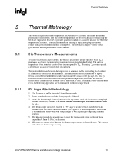
... or junction to ensure an accurate temperature measurement. The hole size through thermocouple leads, or contact between the thermocouple wire and retention mechanism (see Figure 4). Intel® E7500 MCH Thermal and Mechanical Design Guidelines 17 This is the preferred method and is used...
... or junction to ensure an accurate temperature measurement. The hole size through thermocouple leads, or contact between the thermocouple wire and retention mechanism (see Figure 4). Intel® E7500 MCH Thermal and Mechanical Design Guidelines 17 This is the preferred method and is used...
Design Guide
Page 18
... base. Attach a 36 gauge or smaller calibrated K-type thermocouple bead or junction to the MCH, and route thermocouple wires out through the milled slot. 18 Intel® E7500 MCH Thermal and Mechanical Design Guidelines During this step, make room for the thermocouple wire and bead.
... base. Attach a 36 gauge or smaller calibrated K-type thermocouple bead or junction to the MCH, and route thermocouple wires out through the milled slot. 18 Intel® E7500 MCH Thermal and Mechanical Design Guidelines During this step, make room for the thermocouple wire and bead.
Design Guide
Page 19
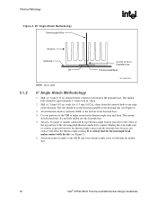
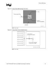
Figure 6. 0° Angle Attach Heatsink Modifications Cement + Thermocouple Bead angle_attach_1 1.3 mm (0.05 in.) (0.5 mm (0.02 in .) Depth) Angle_Attach_Heatsink_Mod Intel® E7500 MCH Thermal and Mechanical Design Guidelines 19 R Figure 5. 0° Angle Attach Methodology (Top View) Thermocouple Wire Thermal Metrology Die Substrate NOTE: Not to scale. 3.3 mm (0.13 in.) Diameter (1.5 mm (0.06 in .) Depth) NOTE: Not to scale.
Figure 6. 0° Angle Attach Heatsink Modifications Cement + Thermocouple Bead angle_attach_1 1.3 mm (0.05 in.) (0.5 mm (0.02 in .) Depth) Angle_Attach_Heatsink_Mod Intel® E7500 MCH Thermal and Mechanical Design Guidelines 19 R Figure 5. 0° Angle Attach Methodology (Top View) Thermocouple Wire Thermal Metrology Die Substrate NOTE: Not to scale. 3.3 mm (0.13 in.) Diameter (1.5 mm (0.06 in .) Depth) NOTE: Not to scale.
Design Guide
Page 20
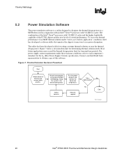
... flowchart for transient time periods. Setup the system in conjunction with an Intel® Xeon™ processor with 512-KB L2 cache and the higher bandwidth capability of the E7500 chipset enables new levels of system performance. Real future applications may exceed ...power supply current requirements under "worst-case realistic application" conditions, Intel has developed a software utility that operates the chipset at near worst-case power dissipation. Yes End Therm_Flowchart 20 Intel® E7500 MCH Thermal and Mechanical Design Guidelines To assess the thermal performance...
... flowchart for transient time periods. Setup the system in conjunction with an Intel® Xeon™ processor with 512-KB L2 cache and the higher bandwidth capability of the E7500 chipset enables new levels of system performance. Real future applications may exceed ...power supply current requirements under "worst-case realistic application" conditions, Intel has developed a software utility that operates the chipset at near worst-case power dissipation. Yes End Therm_Flowchart 20 Intel® E7500 MCH Thermal and Mechanical Design Guidelines To assess the thermal performance...
Design Guide
Page 21
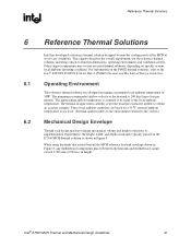
...implementation requirements, the height, width, and depth constraints typically placed on the E7500 MCH thermal solution is shown in height. The approaching airflow temperature is assumed to be equal to the Intel® 82870P2 PCI/PCI-X 64-bit Hub 2 (P64H2) Thermal and Mechanical... temperature of the MCH at the heatsink is 200 lfm (linear feet per minute). Intel® E7500 MCH Thermal and Mechanical Design Guidelines 21 Reference Thermal Solutions R 6 6.1 6.2 Reference Thermal Solutions Intel has developed a reference thermal solution designed to meet the cooling needs of 50 C....
...implementation requirements, the height, width, and depth constraints typically placed on the E7500 MCH thermal solution is shown in height. The approaching airflow temperature is assumed to be equal to the Intel® 82870P2 PCI/PCI-X 64-bit Hub 2 (P64H2) Thermal and Mechanical... temperature of the MCH at the heatsink is 200 lfm (linear feet per minute). Intel® E7500 MCH Thermal and Mechanical Design Guidelines 21 Reference Thermal Solutions R 6 6.1 6.2 Reference Thermal Solutions Intel has developed a reference thermal solution designed to meet the cooling needs of 50 C....


