Design Guide
Page 2
... conflicts or incompatibilities arising from published specifications. Intel products are available on the absence or characteristics of others. Designers must not rely on request. Contact your local Intel sales office or your distributor to sale and/or use in connection with Intel® products. Copyright © 2002 Intel Corporation 2 Intel® E7500 MCH Thermal and Mechanical Design...
... conflicts or incompatibilities arising from published specifications. Intel products are available on the absence or characteristics of others. Designers must not rely on request. Contact your local Intel sales office or your distributor to sale and/or use in connection with Intel® products. Copyright © 2002 Intel Corporation 2 Intel® E7500 MCH Thermal and Mechanical Design...
Design Guide
Page 3
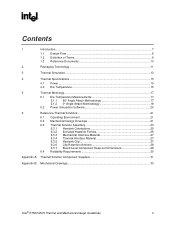
...Contents 1 Introduction ...7 1.1 Design Flow ...8 1.2 Definition of Terms 9 1.3 Reference Documents 10 2 Packaging Technology ...11 3 Thermal Simulation...13 4 Thermal Specifications ...15 4.1 Power ...15 4.2 Die Temperature 15 5 Thermal Metrology...17 5.1 Die Temperature Measurements 17 5.1.1 90° Angle Attach Methodology 17 5.1.2 0°... Level Component Keep-out Dimensions 28 6.4 Reliability Requirements 30 Appendix A: Thermal Solution Component Suppliers 31 Appendix B: Mechanical Drawings...33 Intel® E7500 MCH Thermal and Mechanical Design Guidelines 3
...Contents 1 Introduction ...7 1.1 Design Flow ...8 1.2 Definition of Terms 9 1.3 Reference Documents 10 2 Packaging Technology ...11 3 Thermal Simulation...13 4 Thermal Specifications ...15 4.1 Power ...15 4.2 Die Temperature 15 5 Thermal Metrology...17 5.1 Die Temperature Measurements 17 5.1.1 90° Angle Attach Methodology 17 5.1.2 0°... Level Component Keep-out Dimensions 28 6.4 Reliability Requirements 30 Appendix A: Thermal Solution Component Suppliers 31 Appendix B: Mechanical Drawings...33 Intel® E7500 MCH Thermal and Mechanical Design Guidelines 3
Design Guide
Page 4
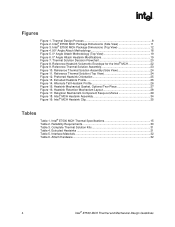
R Figures Figure 1. Thermal Solution Decision Flowchart 20 Figure 8. Reference Heatsink Volumetric Envelope for the Intel® MCH 22 Figure 9. Retention Mechanism Component Keep-out Zones 29 Figure 18. Intel® MCH Heatsink Assembly 34 Figure 19. Intel® E7500 MCH Thermal Specifications 15 Table 2. Reliability Requirements 30 Table 3. Interface Materials 32 Table 6. Reference Thermal Solution Assembly...
R Figures Figure 1. Thermal Solution Decision Flowchart 20 Figure 8. Reference Heatsink Volumetric Envelope for the Intel® MCH 22 Figure 9. Retention Mechanism Component Keep-out Zones 29 Figure 18. Intel® MCH Heatsink Assembly 34 Figure 19. Intel® E7500 MCH Thermal Specifications 15 Table 2. Reliability Requirements 30 Table 3. Interface Materials 32 Table 6. Reference Thermal Solution Assembly...
Design Guide
Page 7
...of fans, vents, and ducts. This document addresses thermal design and specifications for the MCH component only. Heat can be implemented in a system are maintained within thermal specifications. Temperatures exceeding the maximum operating limits may be expected to ensure that...limits of computer systems increases, so do the power dissipation requirements. Introduction R 1 Introduction As the complexity of the Intel® E7500 chipset MCH and describe a reference thermal solution. When additional cooling is required, component thermal solutions may result in ...
...of fans, vents, and ducts. This document addresses thermal design and specifications for the MCH component only. Heat can be implemented in a system are maintained within thermal specifications. Temperatures exceeding the maximum operating limits may be expected to ensure that...limits of computer systems increases, so do the power dissipation requirements. Introduction R 1 Introduction As the complexity of the Intel® E7500 chipset MCH and describe a reference thermal solution. When additional cooling is required, component thermal solutions may result in ...
Design Guide
Page 15
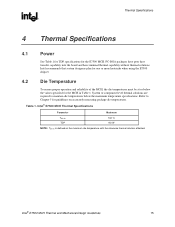
... die temperatures. Table 1. System or component level thermal solutions are required to Chapter 5 for the MCH in Table 1. Thermal Specifications R 4 Thermal Specifications 4.1 Power See Table 1 for TDP specifications for the E7500 MCH. Intel® E7500 MCH Thermal Specifications Parameter Maximum Tdie-hs TDP 102 °C 9.0 W NOTE: Tdie-hs is defined as the maximum die temperature with the...
... die temperatures. Table 1. System or component level thermal solutions are required to Chapter 5 for the MCH in Table 1. Thermal Specifications R 4 Thermal Specifications 4.1 Power See Table 1 for TDP specifications for the E7500 MCH. Intel® E7500 MCH Thermal Specifications Parameter Maximum Tdie-hs TDP 102 °C 9.0 W NOTE: Tdie-hs is defined as the maximum die temperature with the...

Design Guide
Page 16
Thermal Specifications R This page is intentionally left blank. 16 Intel® E7500 MCH Thermal and Mechanical Design Guidelines
Thermal Specifications R This page is intentionally left blank. 16 Intel® E7500 MCH Thermal and Mechanical Design Guidelines
Design Guide
Page 20
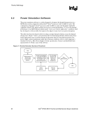
...this software. The utility has been developed solely for the ICC (Max Power Supply Current) specification. Thermal Solution Decision Flowchart Start Attach device to obtain a copy of the Intel® Xeon™ processor with 512-KB L2 cache. Real future applications may exceed the ...process Attach thermocouples using recommended methodology. Setup the system in conjunction with an Intel® Xeon™ processor with 512-KB L2 cache and the higher bandwidth capability of the E7500 chipset enables new levels of an MCH thermal solution under these transient conditions,...
...this software. The utility has been developed solely for the ICC (Max Power Supply Current) specification. Thermal Solution Decision Flowchart Start Attach device to obtain a copy of the Intel® Xeon™ processor with 512-KB L2 cache. Real future applications may exceed the ...process Attach thermocouples using recommended methodology. Setup the system in conjunction with an Intel® Xeon™ processor with 512-KB L2 cache and the higher bandwidth capability of the E7500 chipset enables new levels of an MCH thermal solution under these transient conditions,...
Design Guide
Page 21
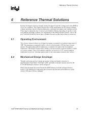
For information on specific system local-ambient operating conditions. The thermal designer must carefully select the location to measure airflow to -function dimensions, operating environment, and...chapter describes the overall requirements for the reference thermal solution, including critical-to obtain an accurate estimate. Intel® E7500 MCH Thermal and Mechanical Design Guidelines 21 Reference Thermal Solutions R 6 6.1 6.2 Reference Thermal Solutions Intel has developed a reference thermal solution designed to meet the cooling needs of 50 C. Other chipset components ...
For information on specific system local-ambient operating conditions. The thermal designer must carefully select the location to measure airflow to -function dimensions, operating environment, and...chapter describes the overall requirements for the reference thermal solution, including critical-to obtain an accurate estimate. Intel® E7500 MCH Thermal and Mechanical Design Guidelines 21 Reference Thermal Solutions R 6 6.1 6.2 Reference Thermal Solutions Intel has developed a reference thermal solution designed to meet the cooling needs of 50 C. Other chipset components ...
Design Guide
Page 26
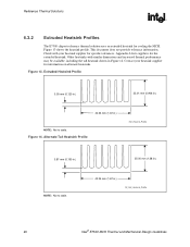
... heatsink. Extruded Heatsink Profile 3.05 mm (0.120 in.) 23.01 mm (0.906 in.) 42.34 mm (1.67 in .) Alt_Extr_Heatsink_Profile 26 Intel® E7500 MCH Thermal and Mechanical Design Guidelines Alternate Tall Heatsink Profile Extr_Heasink_Profile 3.81 mm (0.150 in.) NOTE: Not to scale. 35.00 mm... (1.38 in.) 42.34 mm (1.67 in .) NOTE: Not to scale. Other heatsinks with your heatsink supplier for specific tolerances. ...
... heatsink. Extruded Heatsink Profile 3.05 mm (0.120 in.) 23.01 mm (0.906 in.) 42.34 mm (1.67 in .) Alt_Extr_Heatsink_Profile 26 Intel® E7500 MCH Thermal and Mechanical Design Guidelines Alternate Tall Heatsink Profile Extr_Heasink_Profile 3.81 mm (0.150 in.) NOTE: Not to scale. 35.00 mm... (1.38 in.) 42.34 mm (1.67 in .) NOTE: Not to scale. Other heatsinks with your heatsink supplier for specific tolerances. ...