

Product Specification
Page 6
... PCI Autoconfiguration 72 3.4 System Management BIOS (SMBIOS 73 3.5 Legacy USB Support 73 3.6 BIOS Updates 74 3.6.1 Language Support 74 3.6.2 Custom Splash Screen 74 3.7 BIOS Recovery 75 3.8 Boot Options 75 3.8.1 CD-ROM Boot 75 3.8.2 Network Boot 75 3.8.3 Booting Without Attached Devices 76 3.8.4 Changing the Default Boot Device During POST 76 3.9 Adjusting Boot Speed 76 3.9.1 Peripheral Selection and Configuration 76 3.9.2 BIOS Boot Optimizations 77 3.10 BIOS Security Features 78 4 Error Messages and Beep Codes 4.1 Speaker 79 4.2 BIOS Beep Codes 79 4.3 BIOS Error Messages...
... PCI Autoconfiguration 72 3.4 System Management BIOS (SMBIOS 73 3.5 Legacy USB Support 73 3.6 BIOS Updates 74 3.6.1 Language Support 74 3.6.2 Custom Splash Screen 74 3.7 BIOS Recovery 75 3.8 Boot Options 75 3.8.1 CD-ROM Boot 75 3.8.2 Network Boot 75 3.8.3 Booting Without Attached Devices 76 3.8.4 Changing the Default Boot Device During POST 76 3.9 Adjusting Boot Speed 76 3.9.1 Peripheral Selection and Configuration 76 3.9.2 BIOS Boot Optimizations 77 3.10 BIOS Security Features 78 4 Error Messages and Beep Codes 4.1 Speaker 79 4.2 BIOS Beep Codes 79 4.3 BIOS Error Messages...

Product Specification
Page 7
... and Headers 54 17. Memory Operating Frequencies 17 5. Major Board Components 12 2. Single Channel (Asymmetric) Mode Configuration with Three DIMMs....... 21 9. Front/Back Panel Audio Connector Options 31 11. Localized High Temperature Zones 67 Tables 1. Supported Memory Configurations 16 4. Effects of Conformity Statement 86 5.1.3 Product Ecology Statements 88 5.1.4 EMC Regulations 91 5.1.5 Product Certification Markings (Board Level 92 5.2 Battery Disposal Information 93 Figures 1. LAN Connector LED Locations 33 12. Location of the Onboard Power Indicator LEDs 43...
... and Headers 54 17. Memory Operating Frequencies 17 5. Major Board Components 12 2. Single Channel (Asymmetric) Mode Configuration with Three DIMMs....... 21 9. Front/Back Panel Audio Connector Options 31 11. Localized High Temperature Zones 67 Tables 1. Supported Memory Configurations 16 4. Effects of Conformity Statement 86 5.1.3 Product Ecology Statements 88 5.1.4 EMC Regulations 91 5.1.5 Product Certification Markings (Board Level 92 5.2 Battery Disposal Information 93 Figures 1. LAN Connector LED Locations 33 12. Location of the Onboard Power Indicator LEDs 43...
Product Specification
Page 8
... 17. High Definition Audio Link Header 56 23. Main Power Connector 57 26. Desktop Board DQ965WC Environmental Specifications 69 35. Boot Device Menu Options 76 39. Supervisor and User Password Functions 78 40. Lead-Free Board Markings 90 47. Front Panel Audio Header 56 24. States for a Two-Color Power LED 59 29. BIOS Setup Configuration Jumper Settings 61 31. BIOS Setup Program Function Keys 72 37. Safety Regulations 85 46. System Memory Map 47 12. BIOS Setup Program Menu Bar 72 36. Beep Codes 79 41...
... 17. High Definition Audio Link Header 56 23. Main Power Connector 57 26. Desktop Board DQ965WC Environmental Specifications 69 35. Boot Device Menu Options 76 39. Supervisor and User Password Functions 78 40. Lead-Free Board Markings 90 47. Front Panel Audio Header 56 24. States for a Two-Color Power LED 59 29. BIOS Setup Configuration Jumper Settings 61 31. BIOS Setup Program Function Keys 72 37. Safety Regulations 85 46. System Memory Map 47 12. BIOS Setup Program Menu Bar 72 36. Beep Codes 79 41...

Product Specification
Page 14
...LGA775 Processor Socket System Bus (1066/800/533 MHz) PCI Express x16 Connector PCI Express x16 Interface Display Interface VGA Port Intel Q965 Express Chipset Intel 82Q965 Graphics and Memory Controller Hub (GMCH) PCI Express x1 Interface LPC Bus USB Intel 82801HO I/O Controller Hub (ICH8DO) TPM Component Back Panel/Front Panel USB Ports Serial Peripheral Interface (SPI) Flash Device DMI Interconnect High Definition Audio Link DVI Port Channel A DIMMs (2) Channel B DIMMs (2) Dual-Channel Memory Bus SMBus IEEE-1394a Connector/Header IEEE-1394a PCI Controller Bus Serial ATA IDE...
...LGA775 Processor Socket System Bus (1066/800/533 MHz) PCI Express x16 Connector PCI Express x16 Interface Display Interface VGA Port Intel Q965 Express Chipset Intel 82Q965 Graphics and Memory Controller Hub (GMCH) PCI Express x1 Interface LPC Bus USB Intel 82801HO I/O Controller Hub (ICH8DO) TPM Component Back Panel/Front Panel USB Ports Serial Peripheral Interface (SPI) Flash Device DMI Interconnect High Definition Audio Link DVI Port Channel A DIMMs (2) Channel B DIMMs (2) Dual-Channel Memory Bus SMBus IEEE-1394a Connector/Header IEEE-1394a PCI Controller Bus Serial ATA IDE...

Product Specification
Page 16
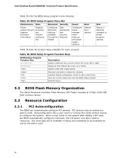
... the DIMMs may not function under the determined frequency. If non-SPD memory is required to correctly configure the memory settings, but performance and reliability may be populated with DIMMs that support the Serial Presence Detect (SPD) data structure. Intel Desktop Board DQ965WC Technical Product Specification 1.4 System Memory The board has four DIMM sockets and supports the following memory features: • 1.8 V (only) DDR2 SDRAM DIMMs with gold...
... the DIMMs may not function under the determined frequency. If non-SPD memory is required to correctly configure the memory settings, but performance and reliability may be populated with DIMMs that support the Serial Presence Detect (SPD) data structure. Intel Desktop Board DQ965WC Technical Product Specification 1.4 System Memory The board has four DIMM sockets and supports the following memory features: • 1.8 V (only) DDR2 SDRAM DIMMs with gold...

Product Specification
Page 27
... driver support. 1.7.1.3 Configuration Modes A list of supported modes for the Intel GMA 3000 graphics controller is available as described in dual channel mode • VGA output • HDTV output • HDMI/UDI support (when used with the HD Audio Link) 27 DVI Port Status Conditions PCI Express x16 connector status No add-in card installed Non-video PCI Express x1 add-in card installed PCI Express x4, x8, or 16 add-in card installed ADD2 or MEC card installed DVI port status Enabled Enabled Disabled Disabled 1.7.1.5 Advanced Digital Display (ADD2/MEC) Card Support...
... driver support. 1.7.1.3 Configuration Modes A list of supported modes for the Intel GMA 3000 graphics controller is available as described in dual channel mode • VGA output • HDTV output • HDMI/UDI support (when used with the HD Audio Link) 27 DVI Port Status Conditions PCI Express x16 connector status No add-in card installed Non-video PCI Express x1 add-in card installed PCI Express x4, x8, or 16 add-in card installed ADD2 or MEC card installed DVI port status Enabled Enabled Disabled Disabled 1.7.1.5 Advanced Digital Display (ADD2/MEC) Card Support...
Product Specification
Page 46
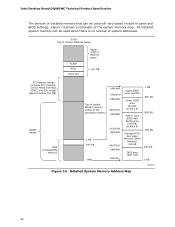
...-in cards and BIOS settings. All installed system memory can be used will vary based on add-in Card BIOS and Buffer area (128 KB; 16 KB x 8) Standard PCI/ ISA Video Memory (SMM Memory) 128 KB DOS area (640 KB) 1 MB 960 KB 896 KB 768 KB 640 KB 0 KB OM18311 Figure 14. Intel Desktop Board DQ965WC Technical Product Specification The amount of installed memory that can be used when...
...-in cards and BIOS settings. All installed system memory can be used will vary based on add-in Card BIOS and Buffer area (128 KB; 16 KB x 8) Standard PCI/ ISA Video Memory (SMM Memory) 128 KB DOS area (640 KB) 1 MB 960 KB 896 KB 768 KB 640 KB 0 KB OM18311 Figure 14. Intel Desktop Board DQ965WC Technical Product Specification The amount of installed memory that can be used when...
Product Specification
Page 71
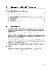
... 3.4 System Management BIOS (SMBIOS 73 3.5 Legacy USB Support 73 3.6 BIOS Updates 74 3.7 BIOS Recovery 75 3.8 Boot Options 75 3.9 Adjusting Boot Speed 76 3.10 BIOS Security Features 78 3.1 Introduction The board uses an Intel BIOS that is powered-up, the BIOS compares the CPU version and the microcode version in the Serial Peripheral Interface Flash Memory (SPI Flash) and can be updated using a disk-based program. The BIOS Setup program can be used to put the board in configure mode. When the BIOS Setup configuration jumper is set to configure mode and the...
... 3.4 System Management BIOS (SMBIOS 73 3.5 Legacy USB Support 73 3.6 BIOS Updates 74 3.7 BIOS Recovery 75 3.8 Boot Options 75 3.9 Adjusting Boot Speed 76 3.10 BIOS Security Features 78 3.1 Introduction The board uses an Intel BIOS that is powered-up, the BIOS compares the CPU version and the microcode version in the Serial Peripheral Interface Flash Memory (SPI Flash) and can be updated using a disk-based program. The BIOS Setup program can be used to put the board in configure mode. When the BIOS Setup configuration jumper is set to configure mode and the...
Product Specification
Page 72
... a user insert or remove PCI cards without having to be onboard or add-in cards. BIOS Setup Program Menu Bar Maintenance Main Advanced Security Clears passwords and displays processor information Displays processor and memory configuration Configures advanced features available through the chipset Sets passwords and security features Power Configures power management features and power supply controls Boot Selects boot options Exit Saves or discards changes to Setup program options Table 36 lists the function keys available for use by the add-in Setup are considered to configure...
... a user insert or remove PCI cards without having to be onboard or add-in cards. BIOS Setup Program Menu Bar Maintenance Main Advanced Security Clears passwords and displays processor information Displays processor and memory configuration Configures advanced features available through the chipset Sets passwords and security features Power Configures power management features and power supply controls Boot Selects boot options Exit Saves or discards changes to Setup program options Table 36 lists the function keys available for use by the add-in Setup are considered to configure...

Product Specification
Page 81
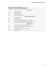
Error Messages and Beep Codes Table 43. Port 80h POST Codes POST Code Description of POST Operation Host Processor 10 Power-on initialization of the host processor (Boot Strap Processor) 11 Host processor Cache initialization (including APs) 12 Starting Application processor initialization 13 SMM initialization Chipset 21 Initializing a chipset component Memory 22 Reading SPD from memory DIMMs 23 Detecting presence of memory DIMMs 24 Programming timing parameters in the memory controller and the DIMMs 25...
Error Messages and Beep Codes Table 43. Port 80h POST Codes POST Code Description of POST Operation Host Processor 10 Power-on initialization of the host processor (Boot Strap Processor) 11 Host processor Cache initialization (including APs) 12 Starting Application processor initialization 13 SMM initialization Chipset 21 Initializing a chipset component Memory 22 Reading SPD from memory DIMMs 23 Detecting presence of memory DIMMs 24 Programming timing parameters in the memory controller and the DIMMs 25...
Product Specification
Page 83
Error Messages and Beep Codes Table 43. Port 80h POST Codes (continued) POST Code Description of POST Operation DXE Drivers E7 Waiting for user input E8 Checking password E9 Entering BIOS setup EB Calling Legacy Option ROMs Runtime Phase/EFI OS Boot F4 Entering Sleep state F5 Exiting Sleep state F8 EFI boot service ExitBootServices ( ) has been called F9 EFI runtime service SetVirtualAddressMap ( ) has been called FA EFI runtime service ResetSystem ( ) has been called PEIMs/Recovery 30 Crisis...
Error Messages and Beep Codes Table 43. Port 80h POST Codes (continued) POST Code Description of POST Operation DXE Drivers E7 Waiting for user input E8 Checking password E9 Entering BIOS setup EB Calling Legacy Option ROMs Runtime Phase/EFI OS Boot F4 Entering Sleep state F5 Exiting Sleep state F8 EFI boot service ExitBootServices ( ) has been called F9 EFI runtime service SetVirtualAddressMap ( ) has been called FA EFI runtime service ResetSystem ( ) has been called PEIMs/Recovery 30 Crisis...
English Product Guide
Page 3
... Information Technology Equipment (I.T.E.) for use in personal computers (PC) for installation in this Product Guide are arranged as follows: 1 Desktop Board Features: a summary of product features 2 Installing and Replacing Desktop Board Components: instructions on how to update the BIOS 4 Configuring for RAID (Intel® Matrix Storage Technology): information about configuring your system for technically qualified personnel. Intended Audience The Product Guide is not intended for Intel® Desktop Board DQ965WC. Preface This Product Guide gives...
... Information Technology Equipment (I.T.E.) for use in personal computers (PC) for installation in this Product Guide are arranged as follows: 1 Desktop Board Features: a summary of product features 2 Installing and Replacing Desktop Board Components: instructions on how to update the BIOS 4 Configuring for RAID (Intel® Matrix Storage Technology): information about configuring your system for technically qualified personnel. Intended Audience The Product Guide is not intended for Intel® Desktop Board DQ965WC. Preface This Product Guide gives...

English Product Guide
Page 6
... the BIOS Configuration Jumper 53 Clearing Passwords 54 Back Panel Connectors 55 3 Updating the BIOS Updating the BIOS with the Intel® Express BIOS Update Utility 61 Updating the BIOS with the ISO Image BIOS Update File or the Iflash Memory Update Utility 62 Obtaining the BIOS Update File 62 Updating the BIOS with the ISO Image BIOS Update File 62 Updating the BIOS with Iflash 63 Recovering the BIOS 64 4 Configuring for RAID (Intel® Matrix Storage Technology) Configuring the BIOS for Intel Matrix Storage Technology 65 SATA Port Mapping 65 Creating Your RAID Set 66 Loading...
... the BIOS Configuration Jumper 53 Clearing Passwords 54 Back Panel Connectors 55 3 Updating the BIOS Updating the BIOS with the Intel® Express BIOS Update Utility 61 Updating the BIOS with the ISO Image BIOS Update File or the Iflash Memory Update Utility 62 Obtaining the BIOS Update File 62 Updating the BIOS with the ISO Image BIOS Update File 62 Updating the BIOS with Iflash 63 Recovering the BIOS 64 4 Configuring for RAID (Intel® Matrix Storage Technology) Configuring the BIOS for Intel Matrix Storage Technology 65 SATA Port Mapping 65 Creating Your RAID Set 66 Loading...
English Product Guide
Page 9
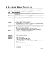
...]) Support for Dual-Independent Display via VGA and DVI-D • PCI Express* graphics card support via a PCI Express x16 connector • 6-channel (5.1) onboard subsystem, featuring: ― Intel® High Definition Audio interface ― SigmaTel* STAC9227 audio codec ― HD Audio Link header • One PCI Express x16 connector • Up to 10 USB 2.0 ports ― Six ports routed to the back panel ― Four ports routed to two USB headers • Four Serial ATA (SATA) channels (3.0 Gb/s), via the ICH8, one device per channel •...
...]) Support for Dual-Independent Display via VGA and DVI-D • PCI Express* graphics card support via a PCI Express x16 connector • 6-channel (5.1) onboard subsystem, featuring: ― Intel® High Definition Audio interface ― SigmaTel* STAC9227 audio codec ― HD Audio Link header • One PCI Express x16 connector • Up to 10 USB 2.0 ports ― Six ports routed to the back panel ― Four ports routed to two USB headers • Four Serial ATA (SATA) channels (3.0 Gb/s), via the ICH8, one device per channel •...
English Product Guide
Page 12
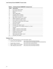
...Hi-speed USB 2.0 headers PCI Express x16 connector Main power connector (2 x 12 pin) BIOS configuration jumper block Front chassis fan header (3-pin) Alternate front panel power LED header Front panel header Processor socket Processor fan header (4-pin) 12 V processor core voltage connector (2 x 2 pin ) Speaker DIMM 1, Channel A and B sockets DIMM 0, Channel A and B sockets Chassis intrusion header Serial ATA connectors Rear chassis fan header (3-pin) HD Audio Link header Related Links: Go to the following links for more information about: • Desktop Board DQ965WC http://www.intel.com...
...Hi-speed USB 2.0 headers PCI Express x16 connector Main power connector (2 x 12 pin) BIOS configuration jumper block Front chassis fan header (3-pin) Alternate front panel power LED header Front panel header Processor socket Processor fan header (4-pin) 12 V processor core voltage connector (2 x 2 pin ) Speaker DIMM 1, Channel A and B sockets DIMM 0, Channel A and B sockets Chassis intrusion header Serial ATA connectors Rear chassis fan header (3-pin) HD Audio Link header Related Links: Go to the following links for more information about: • Desktop Board DQ965WC http://www.intel.com...

English Product Guide
Page 20
... instructions on page 61 in the BIOS reverts all USB 2.0 ports to two internal USB 2.0 headers). Serial ATA and IDE Auto Configuration If you install a Serial ATA or IDE device (such as a hard drive) in the BIOS automatically detects and configures the device for a full-speed USB device. USB 2.0 ports are backward compatible with USB 1.1 devices. You do not support USB 2.0. Use a shielded cable that fully support USB 2.0 transfer rates. Serial ATA The desktop board supports four Serial ATA channels (3.0 Gb/s) via ICH8 (six ports routed to the back panel and four ports...
... instructions on page 61 in the BIOS reverts all USB 2.0 ports to two internal USB 2.0 headers). Serial ATA and IDE Auto Configuration If you install a Serial ATA or IDE device (such as a hard drive) in the BIOS automatically detects and configures the device for a full-speed USB device. USB 2.0 ports are backward compatible with USB 1.1 devices. You do not support USB 2.0. Use a shielded cable that fully support USB 2.0 transfer rates. Serial ATA The desktop board supports four Serial ATA channels (3.0 Gb/s) via ICH8 (six ports routed to the back panel and four ports...

English Product Guide
Page 23
...; Power connectors ― Fan headers ― LAN wake capabilities ― Instantly Available PC technology (Suspend to RAM) ― +5 V standby power indicator LED ― Wake from USB ― Wake from an AC power failure, the computer returns to a tachometer input of the hardware monitoring and control device. • All fan headers support closed-loop fan control that provides full ACPI support. Fan Headers The function/operation of ACPI with the desktop board requires an operating system that can adjust the fan speed or switch...
...; Power connectors ― Fan headers ― LAN wake capabilities ― Instantly Available PC technology (Suspend to RAM) ― +5 V standby power indicator LED ― Wake from USB ― Wake from an AC power failure, the computer returns to a tachometer input of the hardware monitoring and control device. • All fan headers support closed-loop fan control that provides full ACPI support. Fan Headers The function/operation of ACPI with the desktop board requires an operating system that can adjust the fan speed or switch...

English Product Guide
Page 54
... Configure (2-3) Recovery (None) After the Power-On Self-Test (POST) runs, the BIOS displays the Maintenance Menu. Clearing Passwords This procedure assumes that you confirm clearing the password. Turn off all board configurations to the computer. Turn off the computer. Intel Desktop Board DQ965WC Product Guide The three-pin BIOS jumper block enables all peripheral devices connected to be done in the computer, turn on the computer, and allow it to clear passwords. Setup displays the Maintenance menu. 8. Press and Setup displays a pop-up screen...
... Configure (2-3) Recovery (None) After the Power-On Self-Test (POST) runs, the BIOS displays the Maintenance Menu. Clearing Passwords This procedure assumes that you confirm clearing the password. Turn off all board configurations to the computer. Turn off the computer. Intel Desktop Board DQ965WC Product Guide The three-pin BIOS jumper block enables all peripheral devices connected to be done in the computer, turn on the computer, and allow it to clear passwords. Setup displays the Maintenance menu. 8. Press and Setup displays a pop-up screen...
English Product Guide
Page 66
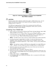
... the original SATA port mapping; Intel Desktop Board DQ965WC Product Guide Figure 32. SATA Port Mapping for a single RAID array is consistent with the SATA port assignment in the RAID array (only if there are installed respectively). Upon re-boot, you have selected the RAID LEVEL. Press and enter the RAID Configuration Utility. 2. In the Intel Matrix Storage Manager option ROM Main Menu, select option #1: Create RAID Volume. Select the drives to be in Figure 32. Exit the Option ROM user interface...
... the original SATA port mapping; Intel Desktop Board DQ965WC Product Guide Figure 32. SATA Port Mapping for a single RAID array is consistent with the SATA port assignment in the RAID array (only if there are installed respectively). Upon re-boot, you have selected the RAID LEVEL. Press and enter the RAID Configuration Utility. 2. In the Intel Matrix Storage Manager option ROM Main Menu, select option #1: Create RAID Volume. Select the drives to be in Figure 32. Exit the Option ROM user interface...
English Product Guide
Page 67
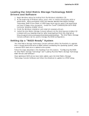
Install the "Intel® ICH8R/DO/DH SATA RAID Controller (Desktop ICH8R)" driver. 3. At the beginning of Windows Setup, press to upgrade from the Internet at http://support.intel.com/support/motherboards/desktop/. Updating the BIOS Loading the Intel Matrix Storage Technology RAID Drivers and Software 1. When prompted, insert the diskette labeled Intel Matrix Storage Technology RAID Driver (Note: A USB floppy drive may be used if the board does not have been added, open the Intel Matrix Storage Technology Console Software and follow the directions to update to the system...
Install the "Intel® ICH8R/DO/DH SATA RAID Controller (Desktop ICH8R)" driver. 3. At the beginning of Windows Setup, press to upgrade from the Internet at http://support.intel.com/support/motherboards/desktop/. Updating the BIOS Loading the Intel Matrix Storage Technology RAID Drivers and Software 1. When prompted, insert the diskette labeled Intel Matrix Storage Technology RAID Driver (Note: A USB floppy drive may be used if the board does not have been added, open the Intel Matrix Storage Technology Console Software and follow the directions to update to the system...


