
D925XHY Technical Product Specification
Page 7
...Port 80h POST Codes 87 4.3 Bus Initialization Checkpoints 91 4.4 Speaker ...92 4.5 BIOS Beep Codes...92 Figures 1. Dual Channel (Interleaved) Mode Configuration with One DIMM 20 8. Dual Channel (Interleaved) Mode Configuration with Four DIMMs 19 7. Dual Channel (Interleaved) Mode Configuration with Three DIMMs 18 6. Single Channel (Asymmetric) Mode Configuration with Three DIMMs 20 9. LAN Connector LED Locations 32 12. Sensors and Fan Connectors 34 13. Location of the Jumper Block 61 21. Detailed System Memory Address Map 44 15. Processor Heatsink for Front Panel...
...Port 80h POST Codes 87 4.3 Bus Initialization Checkpoints 91 4.4 Speaker ...92 4.5 BIOS Beep Codes...92 Figures 1. Dual Channel (Interleaved) Mode Configuration with One DIMM 20 8. Dual Channel (Interleaved) Mode Configuration with Four DIMMs 19 7. Dual Channel (Interleaved) Mode Configuration with Three DIMMs 18 6. Single Channel (Asymmetric) Mode Configuration with Three DIMMs 20 9. LAN Connector LED Locations 32 12. Sensors and Fan Connectors 34 13. Location of the Jumper Block 61 21. Detailed System Memory Address Map 44 15. Processor Heatsink for Front Panel...
D925XHY Technical Product Specification
Page 14
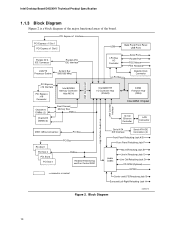
... Port PS/2 Mouse PS/2 Keyboard Diskette Drive Connector PCI Express x16 Interface PCI Express x16 Connector Intel 82925X Memory Controller Hub (MCH) Channel A DIMMs (2) Channel B DIMMs (2) Dual-Channel Memory Bus SMBus Intel 82801FR I/O Controller Hub (ICH6-R) 8 Mbit Firmware Hub (FWH) Intel 925X Chipset 10/100 Ethernet Controller LAN Connector DMI Interconnect High Definition Audio Link LAN Connect Interface IEEE-1394a Connectors PCI Bus PCI Slot 1 PCI Slot 2 PCI Slot 3 PCI Slot 4 PCI Bus SMBus Hardware Monitoring and Fan Control ASIC = connector or socket Serial ATA IDE...
... Port PS/2 Mouse PS/2 Keyboard Diskette Drive Connector PCI Express x16 Interface PCI Express x16 Connector Intel 82925X Memory Controller Hub (MCH) Channel A DIMMs (2) Channel B DIMMs (2) Dual-Channel Memory Bus SMBus Intel 82801FR I/O Controller Hub (ICH6-R) 8 Mbit Firmware Hub (FWH) Intel 925X Chipset 10/100 Ethernet Controller LAN Connector DMI Interconnect High Definition Audio Link LAN Connect Interface IEEE-1394a Connectors PCI Bus PCI Slot 1 PCI Slot 2 PCI Slot 3 PCI Slot 4 PCI Bus SMBus Hardware Monitoring and Fan Control ASIC = connector or socket Serial ATA IDE...
D925XHY Technical Product Specification
Page 23
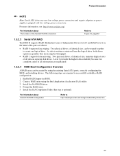
... drives use new low-voltage power connectors and require adaptors or power supplies equipped with low-voltage power connectors. Install the IAA Companion Utility (this step is written or retrieved from the logical drive, both drives operate in BIOS. 2. For information about The location of all data on the Serial ATA ports as follows: • RAID 0 supports data striping. As data is optional). Create a RAID array using the existing Serial ATA ports, correctly configuring the BIOS, and installing drivers...
... drives use new low-voltage power connectors and require adaptors or power supplies equipped with low-voltage power connectors. Install the IAA Companion Utility (this step is written or retrieved from the logical drive, both drives operate in BIOS. 2. For information about The location of all data on the Serial ATA ports as follows: • RAID 0 supports data striping. As data is optional). Create a RAID array using the existing Serial ATA ports, correctly configuring the BIOS, and installing drivers...
D925XHY Technical Product Specification
Page 44
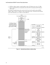
... system memory map. All installed system memory can be used will vary based on add-in Card BIOS and Buffer area (128 KB; 16 KB x 8) Standard PCI/ ISA Video Memory (SMM Memory) 128 KB DOS area (640 KB) 1 MB 960 KB 896 KB 768 KB 640 KB 0 KB OM17140 Figure 14. Intel Desktop Board D925XHY Technical Product Specification • MCH base address registers, internal graphics ranges, PCI Express ports (up...
... system memory map. All installed system memory can be used will vary based on add-in Card BIOS and Buffer area (128 KB; 16 KB x 8) Standard PCI/ ISA Video Memory (SMM Memory) 128 KB DOS area (640 KB) 1 MB 960 KB 896 KB 768 KB 640 KB 0 KB OM17140 Figure 14. Intel Desktop Board D925XHY Technical Product Specification • MCH base address registers, internal graphics ranges, PCI Express ports (up...
D925XHY Technical Product Specification
Page 50
...'s chassis, such as fans and internal peripherals. The figure legend (Table 14) lists the colors used (when applicable). The connectors can be divided into these connectors to power devices external to the computer, the power cable, and the external devices themselves. This section describes the board's connectors. Intel Desktop Board D925XHY Technical Product Specification 2.8 Connectors CAUTION Only the following connectors have overcurrent protection: back panel USB, front panel USB, and PS/2. The other internal connectors are color-coded.
...'s chassis, such as fans and internal peripherals. The figure legend (Table 14) lists the colors used (when applicable). The connectors can be divided into these connectors to power devices external to the computer, the power cable, and the external devices themselves. This section describes the board's connectors. Intel Desktop Board D925XHY Technical Product Specification 2.8 Connectors CAUTION Only the following connectors have overcurrent protection: back panel USB, front panel USB, and PS/2. The other internal connectors are color-coded.
D925XHY Technical Product Specification
Page 77
... 3.2 BIOS Flash Memory Organization 78 3.3 Resource Configuration 78 3.4 System Management BIOS (SMBIOS 79 3.5 Legacy USB Support...79 3.6 BIOS Updates ...80 3.7 Boot Options ...81 3.8 Fast Booting Systems with Intel® Rapid BIOS Boot 82 3.9 BIOS Security Features 83 3.1 Introduction The boards uses an Intel/AMI BIOS that is stored in configure mode. 77 Maintenance Main Advanced Security Power Boot Exit NOTE The maintenance menu is displayed only when the Desktop Board is accessed by pressing the key after the Power-On Self-Test (POST) memory test...
... 3.2 BIOS Flash Memory Organization 78 3.3 Resource Configuration 78 3.4 System Management BIOS (SMBIOS 79 3.5 Legacy USB Support...79 3.6 BIOS Updates ...80 3.7 Boot Options ...81 3.8 Fast Booting Systems with Intel® Rapid BIOS Boot 82 3.9 BIOS Security Features 83 3.1 Introduction The boards uses an Intel/AMI BIOS that is stored in configure mode. 77 Maintenance Main Advanced Security Power Boot Exit NOTE The maintenance menu is displayed only when the Desktop Board is accessed by pressing the key after the Power-On Self-Test (POST) memory test...
D925XHY Technical Product Specification
Page 78
... hard drives up the PCI IDE connector with independent I /O space, and other system resources. Table 37. When a user turns on the system after adding a PCI card, the BIOS automatically configures interrupts, the I /O channel support. BIOS Setup Program Menu Bar Maintenance Main Advanced Security Clears passwords and displays processor information Displays processor and memory configuration Configures advanced features available through the chipset Sets passwords and security features Power Boot Configures power management features and power supply controls Selects boot options...
... hard drives up the PCI IDE connector with independent I /O space, and other system resources. Table 37. When a user turns on the system after adding a PCI card, the BIOS automatically configures interrupts, the I /O channel support. BIOS Setup Program Menu Bar Maintenance Main Advanced Security Clears passwords and displays processor information Displays processor and memory configuration Configures advanced features available through the chipset Sets passwords and security features Power Boot Configures power management features and power supply controls Selects boot options...
D925XHY Technical Product Specification
Page 79
... installation dates for accessing this support, an SMBIOS service-level application running on the same IDE cable as Windows NT*, require an additional interface for managing computers in the BIOS Setup program. The BIOS supports an SMBIOS table interface for such operating systems. Using this information. By default, Legacy USB support is set to enter and configure the BIOS Setup program and the maintenance menu. 4. POST completes. 79 The main component of SMBIOS is a Desktop...
... installation dates for accessing this support, an SMBIOS service-level application running on the same IDE cable as Windows NT*, require an additional interface for managing computers in the BIOS Setup program. The BIOS supports an SMBIOS table interface for such operating systems. Using this information. By default, Legacy USB support is set to enter and configure the BIOS Setup program and the maintenance menu. 4. POST completes. 79 The main component of SMBIOS is a Desktop...
D925XHY Technical Product Specification
Page 82
... seconds of option ROM boot time. Monitors and hard disk drives with minimum initialization times can also contribute to the boot process. • Try different monitors. Intel Desktop Board D925XHY Technical Product Specification 3.8 Fast Booting Systems with Intel® Rapid BIOS Boot These factors affect system boot speed: • Selecting and configuring peripherals properly • Using an optimized BIOS, such as the Intel® Rapid BIOS 3.8.1 Peripheral Selection and Configuration The following BIOS Setup program settings reduces the POST execution...
... seconds of option ROM boot time. Monitors and hard disk drives with minimum initialization times can also contribute to the boot process. • Try different monitors. Intel Desktop Board D925XHY Technical Product Specification 3.8 Fast Booting Systems with Intel® Rapid BIOS Boot These factors affect system boot speed: • Selecting and configuring peripherals properly • Using an optimized BIOS, such as the Intel® Rapid BIOS 3.8.1 Peripheral Selection and Configuration The following BIOS Setup program settings reduces the POST execution...
D925XHY Technical Product Specification
Page 87
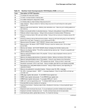
... in card, often called a POST card. D3 Do necessary chipset initialization, start memory refresh, and do memory sizing. D4 Verify base memory. D5 Init code to be copied to segment 0 and control to be installed in F000 Shadow RAM. Compressed recovery code is left at port 80h. E9 Initialize floppy drive. EC Try to recovery code in PCI bus connector 1. EF Booting from floppy failed, look for determining the point where an error occurred. Give two beeps.
... in card, often called a POST card. D3 Do necessary chipset initialization, start memory refresh, and do memory sizing. D4 Verify base memory. D5 Init code to be copied to segment 0 and control to be installed in F000 Shadow RAM. Compressed recovery code is left at port 80h. E9 Initialize floppy drive. EC Try to recovery code in PCI bus connector 1. EF Booting from floppy failed, look for determining the point where an error occurred. Give two beeps.
D925XHY Technical Product Specification
Page 89
... interrupt controller. Patterns written in real mode. Check for soft reset and going to be updated during memory test. Memory above 1M. Memory size display started . Going to relocation/ shadow. Runtime Code Uncompressed in progress. Memory wrap around at 0:0 and finding the total system memory size. Pattern to clear memory below 1M for memory test. Amount of memory below 1M complete. CPU registers are saved. Hit message cleared. Error Messages and Beep Codes...
... interrupt controller. Patterns written in real mode. Check for soft reset and going to be updated during memory test. Memory above 1M. Memory size display started . Going to relocation/ shadow. Runtime Code Uncompressed in progress. Memory wrap around at 0:0 and finding the total system memory size. Pattern to clear memory below 1M for memory test. Amount of memory below 1M complete. CPU registers are saved. Hit message cleared. Error Messages and Beep Codes...
D925XHY Technical Product Specification
Page 92
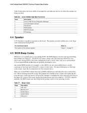
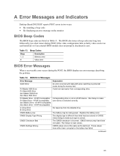
... the bus on page 12 4.5 BIOS Beep Codes Whenever a recoverable error occurs during POST, the BIOS displays an error message describing the problem (see Table 47). The speaker provides audible error code (beep code) information during POST if the video configuration fails (a faulty video card or no card installed) or if an external ROM module does not properly checksum to the operating system. For more information on the board. Table 46. Beep Codes Beep 1 3 6 7 8 Description CPU error Memory error System failure System failure Video error...
... the bus on page 12 4.5 BIOS Beep Codes Whenever a recoverable error occurs during POST, the BIOS displays an error message describing the problem (see Table 47). The speaker provides audible error code (beep code) information during POST if the video configuration fails (a faulty video card or no card installed) or if an external ROM module does not properly checksum to the operating system. For more information on the board. Table 46. Beep Codes Beep 1 3 6 7 8 Description CPU error Memory error System failure System failure Video error...
English Product Guide
Page 3
... connectors and desktop board resources. • A Error Messages and Indicators: information about BIOS error messages and beep codes. • B Regulatory Compliance: safety and EMC regulations, product certification. Preface This Product Guide gives information about entering BIOS Setup and how to important information. Conventions The following conventions are used in this manual: WARNING Warnings indicate conditions that, if not observed, can cause personal injury. Information Layout...
... connectors and desktop board resources. • A Error Messages and Indicators: information about BIOS error messages and beep codes. • B Regulatory Compliance: safety and EMC regulations, product certification. Preface This Product Guide gives information about entering BIOS Setup and how to important information. Conventions The following conventions are used in this manual: WARNING Warnings indicate conditions that, if not observed, can cause personal injury. Information Layout...
English Product Guide
Page 6
... the BIOS for Intel Matrix Storage Technology 40 Creating Your RAID Set 40 Loading the Intel® Application Accelerator Drivers 40 Setting Up a "RAID Ready" System 40 Connecting Internal Headers 41 Front Panel Audio Header 42 IEEE 1394 Headers ...42 USB 2.0 Headers ...42 Front Panel Header...43 Alternate Power LED Header 43 Chassis Intrusion Header 43 Connecting Fans ...44 Connecting Power Cables...45 Installing Other Connectors 47 Setting the BIOS Configuration Jumper Block 48 Clearing Passwords ...49 Back Panel Connectors...50 Setting Up Full 7.1-Channel Surround Sound (Optional...
... the BIOS for Intel Matrix Storage Technology 40 Creating Your RAID Set 40 Loading the Intel® Application Accelerator Drivers 40 Setting Up a "RAID Ready" System 40 Connecting Internal Headers 41 Front Panel Audio Header 42 IEEE 1394 Headers ...42 USB 2.0 Headers ...42 Front Panel Header...43 Alternate Power LED Header 43 Chassis Intrusion Header 43 Connecting Fans ...44 Connecting Power Cables...45 Installing Other Connectors 47 Setting the BIOS Configuration Jumper Block 48 Clearing Passwords ...49 Back Panel Connectors...50 Setting Up Full 7.1-Channel Surround Sound (Optional...
English Product Guide
Page 12
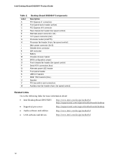
...) Processor fan header (4-pin, fan speed control) Main power connector (2x12) Diskette drive connector IDE connector Battery Chassis intrusion header BIOS configuration jumper Front chassis fan header (fan speed control) Serial ATA connectors (four) Alternate power LED header Front panel header USB 2.0 headers IEEE 1394 headers (blue) Speaker PCI bus add-in card connectors Auxiliary rear fan header (4-pin, fan speed control) Related Links Go to the following links for more information about: • Intel Desktop Board D925XHY http://www.intel.com/design/motherbd http://support.intel.com...
...) Processor fan header (4-pin, fan speed control) Main power connector (2x12) Diskette drive connector IDE connector Battery Chassis intrusion header BIOS configuration jumper Front chassis fan header (fan speed control) Serial ATA connectors (four) Alternate power LED header Front panel header USB 2.0 headers IEEE 1394 headers (blue) Speaker PCI bus add-in card connectors Auxiliary rear fan header (4-pin, fan speed control) Related Links Go to the following links for more information about: • Intel Desktop Board D925XHY http://www.intel.com/design/motherbd http://support.intel.com...
English Product Guide
Page 18
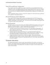
.... Setup options are set , pressing at the password prompt of the chassis intrusion header. 18 Intel Desktop Board D925XHY Product Guide Serial ATA and IDE Auto Configuration If you install a Serial ATA or IDE device (such as a hard drive) in your desktop board, the autoconfiguration utility in the BIOS automatically detects and configures the device for a password. If only the supervisor password is set , you can boot the computer. The security feature uses a mechanical switch on whether the supervisor or user password was entered. • Setting a user password restricts...
.... Setup options are set , pressing at the password prompt of the chassis intrusion header. 18 Intel Desktop Board D925XHY Product Guide Serial ATA and IDE Auto Configuration If you install a Serial ATA or IDE device (such as a hard drive) in your desktop board, the autoconfiguration utility in the BIOS automatically detects and configures the device for a password. If only the supervisor password is set , you can boot the computer. The security feature uses a mechanical switch on whether the supervisor or user password was entered. • Setting a user password restricts...
English Product Guide
Page 40
... RAID Option ROM status message on the remaining portion of Windows Setup, press to upgrade from the Windows installation CD. 2. Creating Your RAID Set 1. When prompted, insert the floppy disk labeled RAID Driver. Go to select RAID 0 or RAID 1, press . 4. Assemble your settings by pressing the key after downloading it from the Internet. Intel Desktop Board D925XHY Product Guide Configuring the System for Intel® Matrix Storage Technology for Serial ATA Configuring the BIOS for RAID 0), and press . 6. Loading the Intel® Application Accelerator Drivers...
... RAID Option ROM status message on the remaining portion of Windows Setup, press to upgrade from the Windows installation CD. 2. Creating Your RAID Set 1. When prompted, insert the floppy disk labeled RAID Driver. Go to select RAID 0 or RAID 1, press . 4. Assemble your settings by pressing the key after downloading it from the Internet. Intel Desktop Board D925XHY Product Guide Configuring the System for Intel® Matrix Storage Technology for Serial ATA Configuring the BIOS for RAID 0), and press . 6. Loading the Intel® Application Accelerator Drivers...
English Product Guide
Page 48
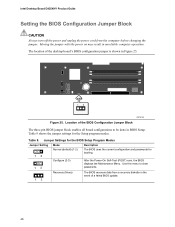
... in BIOS Setup. Table 9 shows the jumper settings for booting. 1 3 Configure (2-3) After the Power-On Self-Test (POST) runs, the BIOS displays the Maintenance Menu. Use this menu to be done in unreliable computer operation. The location of a failed BIOS update. 48 Table 9. Location of the BIOS Configuration Jumper Block The three-pin BIOS jumper block enables all board configurations to clear passwords. 1 3 Recovery (None) The BIOS recovers data from the computer before changing the jumper. Intel Desktop Board D925XHY Product Guide Setting the BIOS Configuration Jumper Block...
... in BIOS Setup. Table 9 shows the jumper settings for booting. 1 3 Configure (2-3) After the Power-On Self-Test (POST) runs, the BIOS displays the Maintenance Menu. Use this menu to be done in unreliable computer operation. The location of a failed BIOS update. 48 Table 9. Location of the BIOS Configuration Jumper Block The three-pin BIOS jumper block enables all board configurations to clear passwords. 1 3 Recovery (None) The BIOS recovers data from the computer before changing the jumper. Intel Desktop Board D925XHY Product Guide Setting the BIOS Configuration Jumper Block...
English Product Guide
Page 63
... short tones) during the memory test. Table 13. A Error Messages and Indicators Desktop Board D925XHY reports POST errors in two ways: • By sounding a beep code • By displaying an error message on the monitor BIOS Beep Codes The BIOS beep codes are not the same as the last boot. Beep Codes Beep 1, 3 8 Description Memory error Video error BIOS Error Messages When a recoverable error occurs during the POST, the BIOS displays an error message describing the problem. Table 14. ATAPI Incompatible Pri Slave Drive - Run Setup to reset values. CMOS Display Type...
... short tones) during the memory test. Table 13. A Error Messages and Indicators Desktop Board D925XHY reports POST errors in two ways: • By sounding a beep code • By displaying an error message on the monitor BIOS Beep Codes The BIOS beep codes are not the same as the last boot. Beep Codes Beep 1, 3 8 Description Memory error Video error BIOS Error Messages When a recoverable error occurs during the POST, the BIOS displays an error message describing the problem. Table 14. ATAPI Incompatible Pri Slave Drive - Run Setup to reset values. CMOS Display Type...
Simplified Chinese Product Guide
Page 40
...; Intel® Application Accelerator 1. 从 Windows Windows 2. 当 Windows F6 SCSI 或 RAID 驱动 RAID Driver(RAID Intel® 82801FR SATA RAID Controller 82801FR SATA RAID 3. 完成 Window 4 Intel Express Installer CD Intel Application Accelerator RAID 配置的 Intel® Storage Utility 设置"RAID SATA Intel Application Accelerator ATA RAID Intel Matrix Storage Technology BIOS"和"加载 Intel Application Accelerator RAID http://support.intel.com/support/motherboards/desktop...
...; Intel® Application Accelerator 1. 从 Windows Windows 2. 当 Windows F6 SCSI 或 RAID 驱动 RAID Driver(RAID Intel® 82801FR SATA RAID Controller 82801FR SATA RAID 3. 完成 Window 4 Intel Express Installer CD Intel Application Accelerator RAID 配置的 Intel® Storage Utility 设置"RAID SATA Intel Application Accelerator ATA RAID Intel Matrix Storage Technology BIOS"和"加载 Intel Application Accelerator RAID http://support.intel.com/support/motherboards/desktop...


