Instruction Manual
Page 2
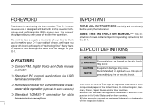
...connection ❍ Remote controller for current mobile transceiver style operation (optional for some versions) ❍ Standard 10BASE-T connector for data transmission/reception i IMPORTANT READ ALL INSTRUCTIONS carefully and completely before using the transceiver. EXPLICIT DEFINITIONS WORD DEFINITION R WARNING! No risk of Microsoft Cor- The ID-1 DIGITAL TRANSCEIVER is designed and built with Icom...'s philosophy of choice, and hope you agree with Icom's superior technology and craftsmanship....
...connection ❍ Remote controller for current mobile transceiver style operation (optional for some versions) ❍ Standard 10BASE-T connector for data transmission/reception i IMPORTANT READ ALL INSTRUCTIONS carefully and completely before using the transceiver. EXPLICIT DEFINITIONS WORD DEFINITION R WARNING! No risk of Microsoft Cor- The ID-1 DIGITAL TRANSCEIVER is designed and built with Icom...'s philosophy of choice, and hope you agree with Icom's superior technology and craftsmanship....
Instruction Manual
Page 6
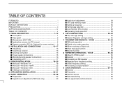
... system 55 General 56 Accessing an FM repeater 57 Repeater tone frequency setting 59 Offset frequency setting 60 Accessing a Digital repeater 61 9 DATA OPERATION 64-70 General 64 Precaution 64 Internet access 65 Data transferring 68 Low-speed data ... screen 4 Remote controller (RC-24; Optional for some versions) ... 9 2 INSTALLATION AND CONNECTIONS 13-17 Unpacking 13 Selecting a location 13 Antenna connection 13 Power supply connections 15 Microphone and speaker connections 16 Connecting a PC 17 3 DRIVER INSTALLATION 18-29 Microsoft® Windows® XP 18 Microsoft®...
... system 55 General 56 Accessing an FM repeater 57 Repeater tone frequency setting 59 Offset frequency setting 60 Accessing a Digital repeater 61 9 DATA OPERATION 64-70 General 64 Precaution 64 Internet access 65 Data transferring 68 Low-speed data ... screen 4 Remote controller (RC-24; Optional for some versions) ... 9 2 INSTALLATION AND CONNECTIONS 13-17 Unpacking 13 Selecting a location 13 Antenna connection 13 Power supply connections 15 Microphone and speaker connections 16 Connecting a PC 17 3 DRIVER INSTALLATION 18-29 Microsoft® Windows® XP 18 Microsoft®...
Instruction Manual
Page 8
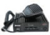
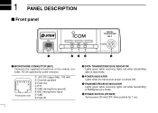
r TRANSMIT/RECEIVE INDICATOR Lights green while receiving; lights red while transmitting in data mode. 1 PANEL DESCRIPTION Front panel DIGITAL TRANSCEIVER ID-1 MIC TD/RD PWR TX/RX POWER q wer t q MICROPHONE CONNECTOR [MIC] Connects the supplied microphone or the remote controller, RC-24 (optional for 1 sec. 1 e POWER INDICATOR Lights while the transceiver power is turned...
r TRANSMIT/RECEIVE INDICATOR Lights green while receiving; lights red while transmitting in data mode. 1 PANEL DESCRIPTION Front panel DIGITAL TRANSCEIVER ID-1 MIC TD/RD PWR TX/RX POWER q wer t q MICROPHONE CONNECTOR [MIC] Connects the supplied microphone or the remote controller, RC-24 (optional for 1 sec. 1 e POWER INDICATOR Lights while the transceiver power is turned...
Instruction Manual
Page 16
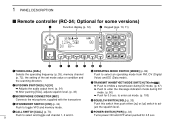
... audio output level. (p. 34) ➥ After pushing [SQL], adjusts squelch level. (p. 33) e MICROPHONE CONNECTOR [MIC] Connects the microphone, supplied with the transceiver. r VFO/MEMORY SWITCH [V/M] (p. 34) Push to select an operating mode from FM, DV (Digital Voice) and DD (Data mode). t CALL SWITCH [CALL] (p. 73) Push to select and toggle call channel...
... audio output level. (p. 34) ➥ After pushing [SQL], adjusts squelch level. (p. 33) e MICROPHONE CONNECTOR [MIC] Connects the microphone, supplied with the transceiver. r VFO/MEMORY SWITCH [V/M] (p. 34) Push to select an operating mode from FM, DV (Digital Voice) and DD (Data mode). t CALL SWITCH [CALL] (p. 73) Push to select and toggle call channel...
Instruction Manual
Page 19
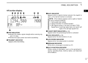
... or the monitor function is one of several conditions. 1. NOTE: If this indicator appears and no audio is heard it is activated. Verify connection of information, such as the operating frequency, operating mode, memory names, set mode item and conditions. 12 r POCKET BEEP INDICATORS (p. 94)... Shows variety of external speaker. 3. Verify audio level setting. 2. u MESSAGE INDICATOR Blinks when a message is in the call signs in use. Digital Voice: Incoming signal does not match call sign squelch list. PANEL DESCRIPTION 1 DFunction display qw er t yu 1294.500 M00 FM RP-
... or the monitor function is one of several conditions. 1. NOTE: If this indicator appears and no audio is heard it is activated. Verify connection of information, such as the operating frequency, operating mode, memory names, set mode item and conditions. 12 r POCKET BEEP INDICATORS (p. 94)... Shows variety of external speaker. 3. Verify audio level setting. 2. u MESSAGE INDICATOR Blinks when a message is in the call signs in use. Digital Voice: Incoming signal does not match call sign squelch list. PANEL DESCRIPTION 1 DFunction display qw er t yu 1294.500 M00 FM RP-
Instruction Manual
Page 62
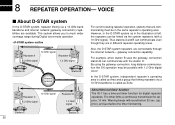
... system, independent repeater's operating area is called as Area and a group that are connectable through the internet network- About time-out timer function The ID-1 has a time-out timer function for approx. 10 min. The timer limits a continuous transmission for digital repeater operation. 8 REPEATER OPERATION- Also, the D-STAR system repeaters are communicating must...
... system, independent repeater's operating area is called as Area and a group that are connectable through the internet network- About time-out timer function The ID-1 has a time-out timer function for approx. 10 min. The timer limits a continuous transmission for digital repeater operation. 8 REPEATER OPERATION- Also, the D-STAR system repeaters are communicating must...
Instruction Manual
Page 68
...call sign is not programmed, enter the call sign into the text box directly. • When linking repeaters via internet network (gateway connection), clicking [G] may be necessary depending on the repeater system. Click if necessary. e Click [RP] several times to select the call ..."YOUR." • When sending a CQ - Click to displays "CQCQCQ" then click [OK]. • When calling the desired station - VOICE Accessing a Digital repeater D Setting from the desired station in "RPT1" then click [OK]. • Click [Z] to display "CQCQCQ" for CQ call sign Click if necessary...
...call sign is not programmed, enter the call sign into the text box directly. • When linking repeaters via internet network (gateway connection), clicking [G] may be necessary depending on the repeater system. Click if necessary. e Click [RP] several times to select the call ..."YOUR." • When sending a CQ - Click to displays "CQCQCQ" then click [OK]. • When calling the desired station - VOICE Accessing a Digital repeater D Setting from the desired station in "RPT1" then click [OK]. • Click [Z] to display "CQCQCQ" for CQ call sign Click if necessary...
Instruction Manual
Page 69
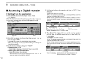
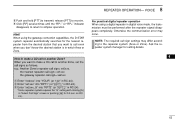
...repeater call signs as follows. Ask the repeater system manager for 0.5 sec. w Enter "xx1xxx" into "YOUR" (or "UR" in digital voice mode, the transmission must be performed after the repeater signal disappears completely. on RC24). VOICE i Push and hold [PTT] to receive.... in RC-24). *Some repeater system requires the "G" setting with clicking [G] in which Area or Zone. For practical digital repeater operation When using the gateway connection capabilities, the D-STAR system repeater automatically searches for the nearest repeater from the desired station that you don't know the ...
...repeater call signs as follows. Ask the repeater system manager for 0.5 sec. w Enter "xx1xxx" into "YOUR" (or "UR" in digital voice mode, the transmission must be performed after the repeater signal disappears completely. on RC24). VOICE i Push and hold [PTT] to receive.... in RC-24). *Some repeater system requires the "G" setting with clicking [G] in which Area or Zone. For practical digital repeater operation When using the gateway connection capabilities, the D-STAR system repeater automatically searches for the nearest repeater from the desired station that you don't know the ...

Instruction Manual
Page 70
...call sign. • Refer to the pages 42 to select the desired station call sign select mode. e Push [RP•4] several times to select DV (Digital voice) mode. • "DV" appears. may be necessary depending on the repeater system. [DIAL] [CS• •1] LOW RPT1:IDRP01 Gå ...to select "RPT2" then set the desired repeater call sign when using the repeater linking capability. • When linking repeaters via internet network (gateway connection), pushing [ ] for call sign setting when the desired call sign select mode, then rotate [DIAL] to 44 for 0.5 sec. LOW 00 ...
...call sign. • Refer to the pages 42 to select the desired station call sign select mode. e Push [RP•4] several times to select DV (Digital voice) mode. • "DV" appears. may be necessary depending on the repeater system. [DIAL] [CS• •1] LOW RPT1:IDRP01 Gå ...to select "RPT2" then set the desired repeater call sign when using the repeater linking capability. • When linking repeaters via internet network (gateway connection), pushing [ ] for call sign setting when the desired call sign select mode, then rotate [DIAL] to 44 for 0.5 sec. LOW 00 ...


