Instruction Manual
Page 1
INSTRUCTION MANUAL DIGITAL TRANSCEIVER ID-1 DIGITAL TRANSCEIVER ID-1 MIC TD/RD PWR TX/RX POWER
INSTRUCTION MANUAL DIGITAL TRANSCEIVER ID-1 DIGITAL TRANSCEIVER ID-1 MIC TD/RD PWR TX/RX POWER
Instruction Manual
Page 2
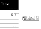
...hope you for data transmission/reception i IMPORTANT READ ALL INSTRUCTIONS carefully and completely before using the transceiver. The ID-1 DIGITAL TRANSCEIVER is designed and built with Icom's philosophy of Icom Incorporated (Japan) in - We want to take a couple of moments of your time to ...thank you agree with Icom's superior technology and craftsmanship. D FEATURES ❍ Current FM, Digital Voice and Data modes ...
...hope you for data transmission/reception i IMPORTANT READ ALL INSTRUCTIONS carefully and completely before using the transceiver. The ID-1 DIGITAL TRANSCEIVER is designed and built with Icom's philosophy of Icom Incorporated (Japan) in - We want to take a couple of moments of your time to ...thank you agree with Icom's superior technology and craftsmanship. D FEATURES ❍ Current FM, Digital Voice and Data modes ...
Instruction Manual
Page 3
... the shared folder may be modified or deleted, or unknown file(s) may be damaged. NEVER place the transceiver where normal operation of Engineering and Technology's report on the rear panel. Icom Inc. Icom also dismisses all responsibility for Human Radio frequency Electromagnetic Fields (OET Bulletin 65). This will damage the...
... the shared folder may be modified or deleted, or unknown file(s) may be damaged. NEVER place the transceiver where normal operation of Engineering and Technology's report on the rear panel. Icom Inc. Icom also dismisses all responsibility for Human Radio frequency Electromagnetic Fields (OET Bulletin 65). This will damage the...
Instruction Manual
Page 4
...Changes or modifications to this unit as far as they can damage the transceiver's surfaces. DO NOT allow children to transmit. The transceiver will soon become hot when op- USE Icom microphones only (supplied or optional). This device may cause signal interference when used ...away from the affected device. Unauthorized reproduction or transmission of this manual, the hardware and software associated with the ID-1, and the appearance of the ID-1 are all intellectual property rights associated with the hardware and software of PC and peripheral devices, follow the instructions...
...Changes or modifications to this unit as far as they can damage the transceiver's surfaces. DO NOT allow children to transmit. The transceiver will soon become hot when op- USE Icom microphones only (supplied or optional). This device may cause signal interference when used ...away from the affected device. Unauthorized reproduction or transmission of this manual, the hardware and software associated with the ID-1, and the appearance of the ID-1 are all intellectual property rights associated with the hardware and software of PC and peripheral devices, follow the instructions...
Instruction Manual
Page 8
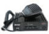
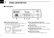
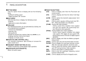
... data in FM/digital voice mode. 1 PANEL DESCRIPTION Front panel DIGITAL TRANSCEIVER ID-1 MIC TD/RD PWR TX/RX POWER q wer t q MICROPHONE CONNECTOR [MIC] Connects the supplied microphone or the remote controller, RC-24 (optional for 1 sec. 1 e POWER INDICATOR Lights while the transceiver power is turned ON. t POWER SWITCH [POWER] Turns power ON...
... data in FM/digital voice mode. 1 PANEL DESCRIPTION Front panel DIGITAL TRANSCEIVER ID-1 MIC TD/RD PWR TX/RX POWER q wer t q MICROPHONE CONNECTOR [MIC] Connects the supplied microphone or the remote controller, RC-24 (optional for 1 sec. 1 e POWER INDICATOR Lights while the transceiver power is turned ON. t POWER SWITCH [POWER] Turns power ON...
Instruction Manual
Page 9
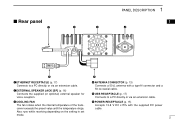
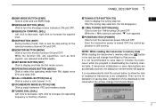
... SPEAKER JACK [SP] (p. 16) Connects the supplied (or optional) external speaker for voice reception. e COOLING FAN The fan rotates when the internal temperature of the transceiver exceeds the preset value until the temperature drops.
... SPEAKER JACK [SP] (p. 16) Connects the supplied (or optional) external speaker for voice reception. e COOLING FAN The fan rotates when the internal temperature of the transceiver exceeds the preset value until the temperature drops.
Instruction Manual
Page 11
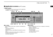
... • Opening a file • Saving (over-write or with different file name) the set contents • Reads the transceivers memory data (See NOTE on PC screen) D Main screen *The application screen can be seen after the application installation. See page 30 for details. Application ...
... • Opening a file • Saving (over-write or with different file name) the set contents • Reads the transceivers memory data (See NOTE on PC screen) D Main screen *The application screen can be seen after the application installation. See page 30 for details. Application ...
Instruction Manual
Page 12
... information t TOOL BAR The following functions can be performed by clicking one of the desired short cut button. • Transceiver initialization • Opening a file • Saving the file • Reads the transceivers memory data (See NOTE on p. 6) • Displays memory channel list screen • Displays set mode screen y AUDIO VOLUME...
... information t TOOL BAR The following functions can be performed by clicking one of the desired short cut button. • Transceiver initialization • Opening a file • Saving the file • Reads the transceivers memory data (See NOTE on p. 6) • Displays memory channel list screen • Displays set mode screen y AUDIO VOLUME...
Instruction Manual
Page 13
... channel (1-3). !8 VFO/MEMORY MODE BUTTON [V/M] Click to switch between VFO and memory mode. !9 TUNING DIAL [DIAL] Left click to turn the transceiver power ON and OFF. After the tuning step selection, the list disappears. @1 1 MHz TUNING BUTTON [MHz] Click to turn the message screen ...BUTTON [POWER] Click to turn the monitor function ON and OFF. Then try the initialization or saving data. If transceiver initialization or save data or initialize the transceiver while the program is still running. While the function ON, any squelches, such as tone squelch, are accidentally ...
... channel (1-3). !8 VFO/MEMORY MODE BUTTON [V/M] Click to switch between VFO and memory mode. !9 TUNING DIAL [DIAL] Left click to turn the transceiver power ON and OFF. After the tuning step selection, the list disappears. @1 1 MHz TUNING BUTTON [MHz] Click to turn the message screen ...BUTTON [POWER] Click to turn the monitor function ON and OFF. Then try the initialization or saving data. If transceiver initialization or save data or initialize the transceiver while the program is still running. While the function ON, any squelches, such as tone squelch, are accidentally ...
Instruction Manual
Page 16
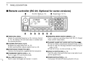
.../DOWN SWITCHES Adjusts the audio output level. (p. 34) ➥ After pushing [SQL], adjusts squelch level. (p. 33) e MICROPHONE CONNECTOR [MIC] Connects the microphone, supplied with the transceiver. e rtyuio q TUNING DIAL [DIAL] Selects the operating frequency (p. 35), memory channel (p. 72), the setting of the set mode. (p. 100) i SQUELCH SWITCH [SQL] (p. 33) Push this...
.../DOWN SWITCHES Adjusts the audio output level. (p. 34) ➥ After pushing [SQL], adjusts squelch level. (p. 33) e MICROPHONE CONNECTOR [MIC] Connects the microphone, supplied with the transceiver. e rtyuio q TUNING DIAL [DIAL] Selects the operating frequency (p. 35), memory channel (p. 72), the setting of the set mode. (p. 100) i SQUELCH SWITCH [SQL] (p. 33) Push this...
Instruction Manual
Page 20
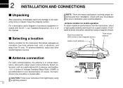
...p. A nonradial antenna should be used when using a lightning arrestor. 13 ID-1 To antenna Keep the shipping cartons. Selecting a location Select a location for mobile operation To obtain maximum performance from the transceiver, select a high-quality antenna and mount it in a good location. Of...proper antennas and their installation. Check with your local dealer for more information and recommendations. • Antenna location for the transceiver that allows adequate air circulation, free from extreme heat, cold, or vibrations, and away from lightning by using a magnetic...
...p. A nonradial antenna should be used when using a lightning arrestor. 13 ID-1 To antenna Keep the shipping cartons. Selecting a location Select a location for mobile operation To obtain maximum performance from the transceiver, select a high-quality antenna and mount it in a good location. Of...proper antennas and their installation. Check with your local dealer for more information and recommendations. • Antenna location for the transceiver that allows adequate air circulation, free from extreme heat, cold, or vibrations, and away from lightning by using a magnetic...
Instruction Manual
Page 22
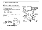
Refer to the diagrams below. • Connecting to a DC power supply DC power supply 13.8 V ID-1 AC outlet −⊕ • Connecting to a vehicle battery Grommet ID-1 _ black + red WARNING! Solder − Black ⊕ Red Fuses 15 A 15 NEVER remove the fuse holders. ⊕ red − black 12 V battery Supplied DC power .... • DC power cable polarity is correct. Red : positive + terminal Black : negative _ terminal Use a DC power supply with a 10 A capacity and above when operating the transceiver with AC power.
Refer to the diagrams below. • Connecting to a DC power supply DC power supply 13.8 V ID-1 AC outlet −⊕ • Connecting to a vehicle battery Grommet ID-1 _ black + red WARNING! Solder − Black ⊕ Red Fuses 15 A 15 NEVER remove the fuse holders. ⊕ red − black 12 V battery Supplied DC power .... • DC power cable polarity is correct. Red : positive + terminal Black : negative _ terminal Use a DC power supply with a 10 A capacity and above when operating the transceiver with AC power.

Instruction Manual
Page 24
... USB extension cable, OPC-1127 (1.5 m; 4.9 ft), if desired. Ask your local computer dealer for details about installing a Ethernet card to USB port PC ID-1 Cable coupler Use the supplied OPC-1069, Ethernet cable (3 m; 9.8 ft), and the cable coupler for the data operation. D PC connection for data operation... PC directly or through an USB hub, use the self-powered type. 17 NOTE: When no Ethernet port is supplied with the transceiver for the connection between the ID-1 and a PC. An USB extension cable, OPC-1127 (1.5 m; 4.9 ft), is available with the cable coupler, if desired.
... USB extension cable, OPC-1127 (1.5 m; 4.9 ft), if desired. Ask your local computer dealer for details about installing a Ethernet card to USB port PC ID-1 Cable coupler Use the supplied OPC-1069, Ethernet cable (3 m; 9.8 ft), and the cable coupler for the data operation. D PC connection for data operation... PC directly or through an USB hub, use the self-powered type. 17 NOTE: When no Ethernet port is supplied with the transceiver for the connection between the ID-1 and a PC. An USB extension cable, OPC-1127 (1.5 m; 4.9 ft), is available with the cable coupler, if desired.
Instruction Manual
Page 39
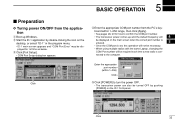
... appropriate COM port number from the application q Boot up and the default frequency will 4 be displayed on the desktop, or select "ID-1" in the program menu. • ID-1 main screen appears and "COM Port Error" may be required each time a new radio is set, this operation will not be ...correct port number is entered. 5 • Once the COM port is con- played for how to confirm the COM port number. • The transceiver power comes up Windows. 5 BASIC OPERATION Preparation D Turing power ON/OFF from the PC's key- board within 1-256) Click t Click [POWER] to the ...
... appropriate COM port number from the application q Boot up and the default frequency will 4 be displayed on the desktop, or select "ID-1" in the program menu. • ID-1 main screen appears and "COM Port Error" may be required each time a new radio is set, this operation will not be ...correct port number is entered. 5 • Once the COM port is con- played for how to confirm the COM port number. • The transceiver power comes up Windows. 5 BASIC OPERATION Preparation D Turing power ON/OFF from the PC's key- board within 1-256) Click t Click [POWER] to the ...
Instruction Manual
Page 40
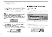
... the squelch level. • Set [SQL] within 9 to turn the power ON. • Pushing [POWER] on the ID-1 front panel also turns power ON. • Push [PWR] (or [POWER] on the function display. • Set...the power OFF. [PWR] Right click to decrease the squelch level. • "SQL" and set level appear on the ID-1 front panel) for 0.5 sec. To turn the function ON and OFF, select "Wakeup PowerON" item in the fi...• The application cannot be quit by turning OFF the transceiver's power only. And also, the transceiver power is still ON even the application is recommended.
... the squelch level. • Set [SQL] within 9 to turn the power ON. • Pushing [POWER] on the ID-1 front panel also turns power ON. • Push [PWR] (or [POWER] on the function display. • Set...the power OFF. [PWR] Right click to decrease the squelch level. • "SQL" and set level appear on the ID-1 front panel) for 0.5 sec. To turn the function ON and OFF, select "Wakeup PowerON" item in the fi...• The application cannot be quit by turning OFF the transceiver's power only. And also, the transceiver power is still ON even the application is recommended.
Instruction Manual
Page 43
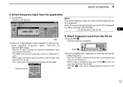
....000 to 1300.000 MHz range. • After the 7th digit is entered, the frequency automatically fixed and set to the transceiver. • Click [ENT] to fix and set to the transceiver. • When a digit is mistakenly input, click [CE] to clear the input, then input from the 1st digit. • Click...
....000 to 1300.000 MHz range. • After the 7th digit is entered, the frequency automatically fixed and set to the transceiver. • Click [ENT] to fix and set to the transceiver. • When a digit is mistakenly input, click [CE] to clear the input, then input from the 1st digit. • Click...
Instruction Manual
Page 44
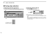
...; When no operation is performed for the selected tuning step 37 "✔" appears for 5 sec., both "TS" and tuning step selection indication disappear and the transceiver return to select the desired tuning step. • 5, 6.25, 10, 12.5, 20, 25, 50 and 100 kHz tuning steps are available.
...; When no operation is performed for the selected tuning step 37 "✔" appears for 5 sec., both "TS" and tuning step selection indication disappear and the transceiver return to select the desired tuning step. • 5, 6.25, 10, 12.5, 20, 25, 50 and 100 kHz tuning steps are available.
Instruction Manual
Page 63
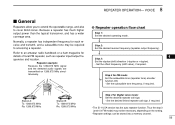
...Refer to an amateur radio handbook or a ham magazine for Digital voice mode: Set the desired repeater call sign, if required. • The ID-1 USA version has the auto repeater function. Set the offset frequency (shift value), if required. Station A: Tx: 1269.975 MHz Rx: 1289....you to extend the operatable range, and also to accessing a repeater. Repeater example; Because a repeater has much higher output power than the typical transceiver, and has a wider coverage area. Set the desired linked repeater call sign. - Normally, a repeater has independent frequency for FM mode: Set...
...Refer to an amateur radio handbook or a ham magazine for Digital voice mode: Set the desired repeater call sign, if required. • The ID-1 USA version has the auto repeater function. Set the offset frequency (shift value), if required. Station A: Tx: 1269.975 MHz Rx: 1289....you to extend the operatable range, and also to accessing a repeater. Repeater example; Because a repeater has much higher output power than the typical transceiver, and has a wider coverage area. Set the desired linked repeater call sign. - Normally, a repeater has independent frequency for FM mode: Set...

Instruction Manual
Page 78
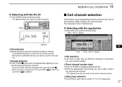
... information* (p. 88) and memory names (pgs 80-82). *Except scan edges and call channels. Click " " in View menu. - 10 MEMORY/CALL OPERATION General description The transceiver has 105 memory channels including 2 scan edge memory channels (1 pair), and 3 call channels. eDouble click, or right click the desired channel's "Select" cell, then select...
... information* (p. 88) and memory names (pgs 80-82). *Except scan edges and call channels. Click " " in View menu. - 10 MEMORY/CALL OPERATION General description The transceiver has 105 memory channels including 2 scan edge memory channels (1 pair), and 3 call channels. eDouble click, or right click the desired channel's "Select" cell, then select...
Instruction Manual
Page 79
... also be used for the direct channel selection. • [CALL] key selection w Click [CALL] each time to select C1 to C3 in sequence. 72 The transceiver has 3 call channel button. lect the desired memory channel. • Channel number indication disappear after pushing [F.INP•L]. • When selecting a channel 00 to se...
... also be used for the direct channel selection. • [CALL] key selection w Click [CALL] each time to select C1 to C3 in sequence. 72 The transceiver has 3 call channel button. lect the desired memory channel. • Channel number indication disappear after pushing [F.INP•L]. • When selecting a channel 00 to se...
