Instruction Manual
Page 2
...modes available ❍ Standard PC control application via USB terminal connection ❍ Remote controller for current mobile transceiver style operation (optional for some versions) ❍ Standard 10BASE-T connector for the ID-1. Microsoft and Windows are registered trademarks or trademarks ...to take a couple of moments of your time to thank you for making your ID-1 your ID-1. poration in - SAVE THIS INSTRUCTION MANUAL- FOREWORD Thank you agree with Icom's philosophy of "technology first." EXPLICIT DEFINITIONS WORD DEFINITION R WARNING! No ...
...modes available ❍ Standard PC control application via USB terminal connection ❍ Remote controller for current mobile transceiver style operation (optional for some versions) ❍ Standard 10BASE-T connector for the ID-1. Microsoft and Windows are registered trademarks or trademarks ...to take a couple of moments of your time to thank you for making your ID-1 your ID-1. poration in - SAVE THIS INSTRUCTION MANUAL- FOREWORD Thank you agree with Icom's philosophy of "technology first." EXPLICIT DEFINITIONS WORD DEFINITION R WARNING! No ...
Instruction Manual
Page 5
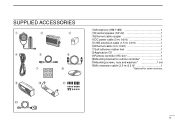
SUPPLIED ACCESSORIES q w e r t u o !0 y i !1 q Microphone (HM-118N 1 w External speaker (SP-22 1 e Ethernet cable coupler 1 r DC power cable (3 m; 9.8 ft 1 t USB extension cable (1.5 m; 4.9 ft 1 y Ethernet cable (3 m; 9.8 ft 1 u Self-adhesive rubber feet 1 i Application CD 1 o Remote controller (RC-24 1 !0 Mounting bracket for remote controller 1 !1 Mounting screws, nuts and washers 1 set !2 Mic extension cable (2.5 m; 8.2 ft 1 *Optional for some versions. !2 iv
SUPPLIED ACCESSORIES q w e r t u o !0 y i !1 q Microphone (HM-118N 1 w External speaker (SP-22 1 e Ethernet cable coupler 1 r DC power cable (3 m; 9.8 ft 1 t USB extension cable (1.5 m; 4.9 ft 1 y Ethernet cable (3 m; 9.8 ft 1 u Self-adhesive rubber feet 1 i Application CD 1 o Remote controller (RC-24 1 !0 Mounting bracket for remote controller 1 !1 Mounting screws, nuts and washers 1 set !2 Mic extension cable (2.5 m; 8.2 ft 1 *Optional for some versions. !2 iv
Instruction Manual
Page 9
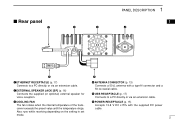
...) external speaker for voice reception. e COOLING FAN The fan rotates when the internal temperature of the transceiver exceeds the preset value until the temperature drops. t USB RECEPTACLE (p. 17) Connects to a PC directly, or via an extension cable. y r ANTENNA CONNECTOR (p. 13) Connects a 50 Ω antenna with the supplied DC power cable. 2 Rear...
...) external speaker for voice reception. e COOLING FAN The fan rotates when the internal temperature of the transceiver exceeds the preset value until the temperature drops. t USB RECEPTACLE (p. 17) Connects to a PC directly, or via an extension cable. y r ANTENNA CONNECTOR (p. 13) Connects a 50 Ω antenna with the supplied DC power cable. 2 Rear...

Instruction Manual
Page 24
...-powered type. 17 NOTE: When no Ethernet port is supplied with the cable coupler, if desired. An USB extension cable, OPC-1127 (1.5 m; 4.9 ft), is available with your computer. ID-1 Use the supplied USB extension cable, OPC-1127 (1.5 m; 4.9 ft), if desired. Connect the Ethernet receptacle to your PC, ... PC connection for data operation Ethernet cable connection is used for extension, if desired. Ethernet card PC to Ethernet port to USB port PC ID-1 Cable coupler Use the supplied OPC-1069, Ethernet cable (3 m; 9.8 ft), and the cable coupler for the connection between the...
...-powered type. 17 NOTE: When no Ethernet port is supplied with the cable coupler, if desired. An USB extension cable, OPC-1127 (1.5 m; 4.9 ft), is available with your computer. ID-1 Use the supplied USB extension cable, OPC-1127 (1.5 m; 4.9 ft), if desired. Connect the Ethernet receptacle to your PC, ... PC connection for data operation Ethernet cable connection is used for extension, if desired. Ethernet card PC to Ethernet port to USB port PC ID-1 Cable coupler Use the supplied OPC-1069, Ethernet cable (3 m; 9.8 ft), and the cable coupler for the connection between the...
Instruction Manual
Page 25
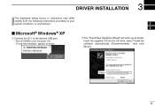
Insert the supplied CD into the CD drive, select "Install the software automatically (Recommended)," then click [Next>]. 3 DRIVER INSTALLATION The displayed dialog boxes or indications may differ slightly from the following instructions according to turn the power ON. • "Found New Hardware" appears as below. 2 3 wThe "Found New Hardware Wizard" will come up as below. Select Click 18 Microsoft® Windows® XP q Connect the ID-1 to the desired USB port. • Push [POWER] to your system conditions, or environment.
Insert the supplied CD into the CD drive, select "Install the software automatically (Recommended)," then click [Next>]. 3 DRIVER INSTALLATION The displayed dialog boxes or indications may differ slightly from the following instructions according to turn the power ON. • "Found New Hardware" appears as below. 2 3 wThe "Found New Hardware Wizard" will come up as below. Select Click 18 Microsoft® Windows® XP q Connect the ID-1 to the desired USB port. • Push [POWER] to your system conditions, or environment.
Instruction Manual
Page 26
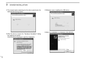
t Windows starts installing the USB driver. Click [Continue Anyway] to start the installation. y After the installation is found, the "Hardware Installation" dialog box appears as below during search. 3 DRIVER INSTALLATION eThe wizard starts searching for the driver and shows the dialog below . Click 19 Click rAfter the driver is completed, click [Finish].
t Windows starts installing the USB driver. Click [Continue Anyway] to start the installation. y After the installation is found, the "Hardware Installation" dialog box appears as below during search. 3 DRIVER INSTALLATION eThe wizard starts searching for the driver and shows the dialog below . Click 19 Click rAfter the driver is completed, click [Finish].

Instruction Manual
Page 27
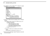
Select "Install the software automatically (Recommended)," then click [Next>]. Click [Continue Anyway] to install the USB serial port driver. 3 DRIVER INSTALLATION uThe "Found New Hardware Wizard" will come up again to start the installation. 3 Select Click Click o Windows starts installing the USB driver. 20 iAfter the driver is found, the "Hardware Installation" dialog box appears as below.
Select "Install the software automatically (Recommended)," then click [Next>]. Click [Continue Anyway] to install the USB serial port driver. 3 DRIVER INSTALLATION uThe "Found New Hardware Wizard" will come up again to start the installation. 3 Select Click Click o Windows starts installing the USB driver. 20 iAfter the driver is found, the "Hardware Installation" dialog box appears as below.

Instruction Manual
Page 29
... installation, eject the CD. • Rebooting the PC is found , click [OK]. t Click [OK]. • Push [POWER] to the desired USB port. Click eInsert the supplied CD into the drive. q Click to select the appropriate CD-ROM drive then click "Driver" folder. Click Click [Browse...].... rClick [Z] to select 22 3 DRIVER INSTALLATION Microsoft® Windows® 98/Me q Connect the ID-1 to turn the power ON. • The driver installation starts. 3 • "New Hardware is recommended. wThe "New Hardware Found" will come...
... installation, eject the CD. • Rebooting the PC is found , click [OK]. t Click [OK]. • Push [POWER] to the desired USB port. Click eInsert the supplied CD into the drive. q Click to select the appropriate CD-ROM drive then click "Driver" folder. Click Click [Browse...].... rClick [Z] to select 22 3 DRIVER INSTALLATION Microsoft® Windows® 98/Me q Connect the ID-1 to turn the power ON. • The driver installation starts. 3 • "New Hardware is recommended. wThe "New Hardware Found" will come...

Instruction Manual
Page 30
3 DRIVER INSTALLATION Microsoft® Windows® 2000 q Connect the ID-1 to the desired USB port. • Push [POWER] to turn the power ON. • "Found New Hardware" dialog box appears below . eSelect "Search for a suitable driver for my device (recommended)," then click [Next>]. wThe "Found New Hardware Wizard" will come up as below . Click [Next>]. Select Click Click 23
3 DRIVER INSTALLATION Microsoft® Windows® 2000 q Connect the ID-1 to the desired USB port. • Push [POWER] to turn the power ON. • "Found New Hardware" dialog box appears below . eSelect "Search for a suitable driver for my device (recommended)," then click [Next>]. wThe "Found New Hardware Wizard" will come up as below . Click [Next>]. Select Click Click 23
Instruction Manual
Page 36
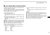
Click uConfirm the USB serial port availability and the COM port number. • The COM port number is used for the COM port setup. (p. 32) Confirm the USB serial port availability and the COM port number. (In this example, the USB serial port number is "4.") iClose the Device Manager, System Properties screen and then Control panel. 29 3 DRIVER INSTALLATION yClick " " of the "Ports (COM & LPT)" to display the usable COM port and the port number.
Click uConfirm the USB serial port availability and the COM port number. • The COM port number is used for the COM port setup. (p. 32) Confirm the USB serial port availability and the COM port number. (In this example, the USB serial port number is "4.") iClose the Device Manager, System Properties screen and then Control panel. 29 3 DRIVER INSTALLATION yClick " " of the "Ports (COM & LPT)" to display the usable COM port and the port number.
Instruction Manual
Page 77
...simultaneously, due to both of data) may occur depending on the RC24. NOTE: • A communication error may occur when communicating through the ID-1 USB port. nication application installed in File menu to quit the application. w Select DV (Digital voice) mode. • Click [MODE] on the... main screen or push [MODE] on the com- eSet another settings, such as ID-1's • Baud rate : 19200 bps • Data : 8 bit • Parity : None • Stop : 1 bit • Flow control : Xon/Xoff...
...simultaneously, due to both of data) may occur depending on the RC24. NOTE: • A communication error may occur when communicating through the ID-1 USB port. nication application installed in File menu to quit the application. w Select DV (Digital voice) mode. • Click [MODE] on the... main screen or push [MODE] on the com- eSet another settings, such as ID-1's • Baud rate : 19200 bps • Data : 8 bit • Parity : None • Stop : 1 bit • Flow control : Xon/Xoff...
Instruction Manual
Page 123
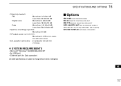
... EXTERNAL SPEAKERS 16 116 speaker connectors : 2-conductor 3.5 (d) mm (1⁄8″)/8 Ω D SYSTEM REQUIREMENTS • Microsoft® Windows® 98/98SE/Me/2000/XP • An USB port • Ethernet port (for Data operation) All stated specifications are subject to change without notice or obligation.
... EXTERNAL SPEAKERS 16 116 speaker connectors : 2-conductor 3.5 (d) mm (1⁄8″)/8 Ω D SYSTEM REQUIREMENTS • Microsoft® Windows® 98/98SE/Me/2000/XP • An USB port • Ethernet port (for Data operation) All stated specifications are subject to change without notice or obligation.