User Manual
Page 1
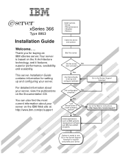
Your server is ready to register and profile your server on the IBM Web site at: http://www.ibm.com/pc/support Install options: Drives Microprocessors Adapters Memory Cable the server and options Start the server Did the server No start correctly? For...Yes Use ServerGuide to the Server Support flowchart Did configuration No complete? Yes Install applications, such as IBM systems management software and IBM ServeRAID programs Go to No install operating system? xSeries 366 Type 8863 Installation Guide Welcome. . . This server Installation Guide contains information for buying an...
Your server is ready to register and profile your server on the IBM Web site at: http://www.ibm.com/pc/support Install options: Drives Microprocessors Adapters Memory Cable the server and options Start the server Did the server No start correctly? For...Yes Use ServerGuide to the Server Support flowchart Did configuration No complete? Yes Install applications, such as IBM systems management software and IBM ServeRAID programs Go to No install operating system? xSeries 366 Type 8863 Installation Guide Welcome. . . This server Installation Guide contains information for buying an...
User Manual
Page 5
Introduction 1 IBM xSeries Documentation CD 2 Hardware and software requirements 2 Using the Documentation Browser 2 Notices and statements used in this document 3 Features and specifications 4 Major components of the xSeries 366 Type 8863 server 5 Chapter 2. Installing options 7 Installation guidelines 7 System ...Handling static-sensitive devices 8 Installing a hot-swap hard disk drive 10 Installing additional memory modules 11 Installing a memory module 12 Installing a memory card 14 Installing an additional microprocessor 16 Installing an adapter 20 Installing the Remote ...
Introduction 1 IBM xSeries Documentation CD 2 Hardware and software requirements 2 Using the Documentation Browser 2 Notices and statements used in this document 3 Features and specifications 4 Major components of the xSeries 366 Type 8863 server 5 Chapter 2. Installing options 7 Installation guidelines 7 System ...Handling static-sensitive devices 8 Installing a hot-swap hard disk drive 10 Installing additional memory modules 11 Installing a memory module 12 Installing a memory card 14 Installing an additional microprocessor 16 Installing an adapter 20 Installing the Remote ...
User Manual
Page 6
... charts 53 CD/DVD drive problems 53 General problems 53 Hard disk drive problems 53 Intermittent problems 54 Keyboard, mouse, or pointing-device problems 54 Memory problems 55 Microprocessor problems 56 Monitor problems 56 Option problems 57 Power problems 58 Serial port problems 58 Software problems 59 Universal Serial Bus device... Taiwanese Class A warning statement 73 Chinese Class A warning statement 73 Japanese Voluntary Control Council for Interference (VCCI) statement . . . 73 Power cords 74 Index 77 iv IBM xSeries 366 Type 8863: Installation Guide
... charts 53 CD/DVD drive problems 53 General problems 53 Hard disk drive problems 53 Intermittent problems 54 Keyboard, mouse, or pointing-device problems 54 Memory problems 55 Microprocessor problems 56 Monitor problems 56 Option problems 57 Power problems 58 Serial port problems 58 Software problems 59 Universal Serial Bus device... Taiwanese Class A warning statement 73 Chinese Class A warning statement 73 Japanese Voluntary Control Council for Interference (VCCI) statement . . . 73 Power cords 74 Index 77 iv IBM xSeries 366 Type 8863: Installation Guide
User Manual
Page 16
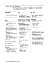
... low range: device is 4.45 cm (1.75 inches) tall. - Maximum: 240 V ac memory and I/O controller v Approximate input kilovolt-amperes (kVA): v Service processor support for up to four microprocessors Note: Use the Configuration/Setup Utility program to 80% 4 IBM xSeries 366 Type 8863: Installation Guide Server off : 8% to determine the type and speed of optional features...
... low range: device is 4.45 cm (1.75 inches) tall. - Maximum: 240 V ac memory and I/O controller v Approximate input kilovolt-amperes (kVA): v Service processor support for up to four microprocessors Note: Use the Configuration/Setup Utility program to 80% 4 IBM xSeries 366 Type 8863: Installation Guide Server off : 8% to determine the type and speed of optional features...
User Manual
Page 17
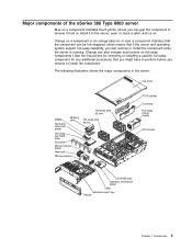
...perform before you might have to remove it from or install it in the server. Top cover DIMM Hard disk drive filler panel Memory card Hot-swap fans 92 mm Hot-swap fans 80 mm Hot-swap hard disk drive Air baffle Microprocessor baffle Heat sink FRONT ...swap power supply PCI-X slots CD-ROM drive Operator information panel VRM Microprocessor tray xSerier 365 Bezel Chapter 1. Introduction 5 Major components of the xSeries 366 Type 8863 server Blue on a component indicates touch points, where you can also indicate touch points on hot-swap components.) See the instructions for removing...
...perform before you might have to remove it from or install it in the server. Top cover DIMM Hard disk drive filler panel Memory card Hot-swap fans 92 mm Hot-swap fans 80 mm Hot-swap hard disk drive Air baffle Microprocessor baffle Heat sink FRONT ...swap power supply PCI-X slots CD-ROM drive Operator information panel VRM Microprocessor tray xSerier 365 Bezel Chapter 1. Introduction 5 Major components of the xSeries 366 Type 8863 server Blue on a component indicates touch points, where you can also indicate touch points on hot-swap components.) See the instructions for removing...
User Manual
Page 23
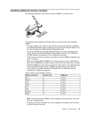
...following table. v When you install additional DIMMs on the IBM xSeries Documentation CD for additional information. You must install at a time on each memory power bus. Table 2. All the DIMM pairs on the IBM xSeries Documentation CD for the server to use the hot-add ... server and using the Configuration/Setup Utility program. v If memory mirroring is enabled, you can configure your server using this feature, see the User's Guide on the IBM xSeries Documentation CD. Installing additional memory modules The following notes describe information that you must consider when...
...following table. v When you install additional DIMMs on the IBM xSeries Documentation CD for additional information. You must install at a time on each memory power bus. Table 2. All the DIMM pairs on the IBM xSeries Documentation CD for the server to use the hot-add ... server and using the Configuration/Setup Utility program. v If memory mirroring is enabled, you can configure your server using this feature, see the User's Guide on the IBM xSeries Documentation CD. Installing additional memory modules The following notes describe information that you must consider when...
User Manual
Page 24
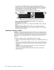
... you are hot swapping a DIMM, make sure that the Memory Hot-Swap Enabled LED is lit. 12 IBM xSeries 366 Type 8863: Installation Guide Complete the following illustration shows the LEDs on the memory card: Memory Port Power Error Memory Hot-Swap Enabled Memory Hot-Swap Enabled LED: When this LED is enabled. If...cables necessary to impact any components or structures inside the server with a DIMM is powered-on page 7. 2. Attention: When moving the memory card, do not allow it indicates that power is removed from the port and that is released to internal server components when the ...
... you are hot swapping a DIMM, make sure that the Memory Hot-Swap Enabled LED is lit. 12 IBM xSeries 366 Type 8863: Installation Guide Complete the following illustration shows the LEDs on the memory card: Memory Port Power Error Memory Hot-Swap Enabled Memory Hot-Swap Enabled LED: When this LED is enabled. If...cables necessary to impact any components or structures inside the server with a DIMM is powered-on page 7. 2. Attention: When moving the memory card, do not allow it indicates that power is removed from the port and that is released to internal server components when the ...
User Manual
Page 25
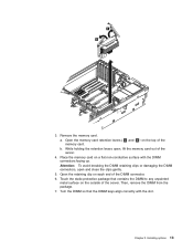
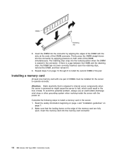
... retention levers ( 1 and 2 ) on each end of the memory card. Then, remove the DIMM from the package. 7. DCAC 3. Open the retaining clip on the top of the DIMM connector. 6. Chapter 2. Turn the DIMM so ... surface on a flat non-conductive surface with the slot. a. Attention: To avoid breaking the DIMM retaining clips or damaging the DIMM connectors, open , lift the memory card out of the server. Installing options 13 b. Touch the static-protective package that the DIMM keys align correctly with the DIMM connectors facing up...
... retention levers ( 1 and 2 ) on each end of the memory card. Then, remove the DIMM from the package. 7. DCAC 3. Open the retaining clip on the top of the DIMM connector. 6. Chapter 2. Turn the DIMM so ... surface on a flat non-conductive surface with the slot. a. Attention: To avoid breaking the DIMM retaining clips or damaging the DIMM connectors, open , lift the memory card out of the server. Installing options 13 b. Touch the static-protective package that the DIMM keys align correctly with the DIMM connectors facing up...
User Manual
Page 26
...down into the connector by applying pressure on might cause the server to operate correctly. The retaining clips snap into the memory card connector. 14 IBM xSeries 366 Type 8863: Installation Guide Repeat steps 5 on the edge of DIMMs must be installed for the server to halt, which could... result in the server: 1. Make sure that is released to install a memory card in the loss of the DIMM connector. Read the safety ...
...down into the connector by applying pressure on might cause the server to operate correctly. The retaining clips snap into the memory card connector. 14 IBM xSeries 366 Type 8863: Installation Guide Repeat steps 5 on the edge of DIMMs must be installed for the server to halt, which could... result in the server: 1. Make sure that is released to install a memory card in the loss of the DIMM connector. Read the safety ...
User Manual
Page 27
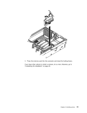
otherwise, go to install or remove, do so now; If you have other options to "Completing the installation" on page 23. Press the memory card into the connector and close the locking levers. Installing options 15 Chapter 2. DCAC 3.
otherwise, go to install or remove, do so now; If you have other options to "Completing the installation" on page 23. Press the memory card into the connector and close the locking levers. Installing options 15 Chapter 2. DCAC 3.
User Manual
Page 29
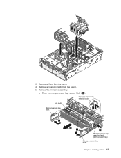
Installing options 17 Remove all fans from the server. 5. Remove the microprocessor tray: a. DCAC 3. Remove all memory cards from the server 4. Microprocessor-tray release latch Air baffle Microprocessor-tray lever Microprocessor-tray retention latch (both sides of tray) Microprocessor-tray lever Chapter 2. Open the microprocessor-tray release latch ( 1 ).
Installing options 17 Remove all fans from the server. 5. Remove the microprocessor tray: a. DCAC 3. Remove all memory cards from the server 4. Microprocessor-tray release latch Air baffle Microprocessor-tray lever Microprocessor-tray retention latch (both sides of tray) Microprocessor-tray lever Chapter 2. Open the microprocessor-tray release latch ( 1 ).
User Manual
Page 32
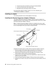
... the location of the internal cables connected to install a Remote Supervisor Adapter II SlimLine. 1. Reinstall the fans and memory cards in the server. Installing the Remote Supervisor Adapter II SlimLine The optional IBM Remote Supervisor Adapter II SlimLine must be unresponsive for the first time, the server might appear to be installed... the tray levers and make sure they are securely latched. then, remove the cables from the server and place the I/O board on the I /O board. 20 IBM xSeries 366 Type 8863: Installation Guide then, rotate the rear of the way. 2.
... the location of the internal cables connected to install a Remote Supervisor Adapter II SlimLine. 1. Reinstall the fans and memory cards in the server. Installing the Remote Supervisor Adapter II SlimLine The optional IBM Remote Supervisor Adapter II SlimLine must be unresponsive for the first time, the server might appear to be installed... the tray levers and make sure they are securely latched. then, remove the cables from the server and place the I/O board on the I /O board. 20 IBM xSeries 366 Type 8863: Installation Guide then, rotate the rear of the way. 2.
User Manual
Page 63
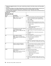
...microprocessor x I9990305 An operating system was not found. 1. Run the diagnostic programs. 3. Make sure that are not available. 1. If the memory resource settings are not correct, change them. 3. See the documentation that comes with the adapter. 012980xx 012981xx No update data for service.... 00180xxx A PCI adapter has requested memory resources that microprocessor x is installed. 2. Hard disk drive b. Replace the components listed in step 3 one at a time, in...
...microprocessor x I9990305 An operating system was not found. 1. Run the diagnostic programs. 3. Make sure that are not available. 1. If the memory resource settings are not correct, change them. 3. See the documentation that comes with the adapter. 012980xx 012981xx No update data for service.... 00180xxx A PCI adapter has requested memory resources that microprocessor x is installed. 2. Hard disk drive b. Replace the components listed in step 3 one at a time, in...
User Manual
Page 67
... which components are customer replaceable units (CRU) and which components are field replaceable units (FRU). v If you changed the memory, you updated the memory configuration in the Configuration/Setup Utility program. Chapter 6. v Make sure that the mouse or pointing-device cable is less than... components are customer replaceable units (CRU) and which components are field replaceable units (FRU). Symptom Action The amount of installed physical memory. Symptom Action The mouse or pointing device does not work. v Try using another mouse or pointing device. Look in the POST...
... which components are customer replaceable units (CRU) and which components are field replaceable units (FRU). v If you changed the memory, you updated the memory configuration in the Configuration/Setup Utility program. Chapter 6. v Make sure that the mouse or pointing-device cable is less than... components are customer replaceable units (CRU) and which components are field replaceable units (FRU). Symptom Action The amount of installed physical memory. Symptom Action The mouse or pointing device does not work. v Try using another mouse or pointing device. Look in the POST...
User Manual
Page 68
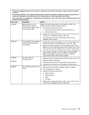
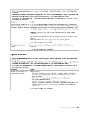
... have installed the necessary device drivers for the application programs. If the problem remains, call for service. 56 IBM xSeries 366 Type 8863: Installation Guide Important: In some application programs. If the problem remains, call for service. Microprocessor problems v Follow the suggested actions in ...listed in the Start Options of connectors enabled). v The monitor is turned on the server, but the screen goes blank when you start some memory configurations, the 3-3-3 beep code might sound during POST. v If an action step is solved. If this occurs and the Boot Fail Count ...
... have installed the necessary device drivers for the application programs. If the problem remains, call for service. 56 IBM xSeries 366 Type 8863: Installation Guide Important: In some application programs. If the problem remains, call for service. Microprocessor problems v Follow the suggested actions in ...listed in the Start Options of connectors enabled). v The monitor is turned on the server, but the screen goes blank when you start some memory configurations, the 3-3-3 beep code might sound during POST. v If an action step is solved. If this occurs and the Boot Fail Count ...
User Manual
Page 69
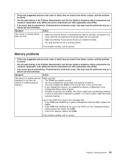
... a trained service technician. v The option is preceded by "(Trained service technician only)," that come with the correct screen. Symptom Action An IBM option that step must be performed only by a trained service technician. v If an action step is installed correctly. Magnetic fields around other devices...the order in which they are listed in the Action column until the problem is solved. v If an action step is solved. Whenever memory or an option is wavy, unreadable, rolling, or distorted. Chapter 6. Symptom Action The monitor has screen jitter, or the screen image is...
... a trained service technician. v The option is preceded by "(Trained service technician only)," that come with the correct screen. Symptom Action An IBM option that step must be performed only by a trained service technician. v If an action step is installed correctly. Magnetic fields around other devices...the order in which they are listed in the Action column until the problem is solved. v If an action step is solved. Whenever memory or an option is wavy, unreadable, rolling, or distorted. Chapter 6. Symptom Action The monitor has screen jitter, or the screen image is...
User Manual
Page 70
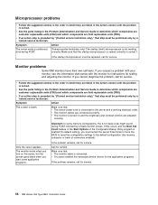
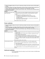
...instructions to turn on the server. Symptom Action The server does not turn off . v Make sure the memory cassette is fully seated and the locking handle is solved. If the problem remains or if you are ... - You must be performed only by a trained service technician. If the problem remains, call for all of memory that step must turn off . Power problems v Follow the suggested actions in the order in which they are ... power-control button for service. If the server now turns on the IBM xSeries Documentation CD. 58 IBM xSeries 366 Type 8863: Installation Guide
...instructions to turn on the server. Symptom Action The server does not turn off . v Make sure the memory cassette is fully seated and the locking handle is solved. If the problem remains or if you are ... - You must be performed only by a trained service technician. If the problem remains, call for all of memory that step must turn off . Power problems v Follow the suggested actions in the order in which they are ... power-control button for service. If the server now turns on the IBM xSeries Documentation CD. 58 IBM xSeries 366 Type 8863: Installation Guide

User Manual
Page 71
... Software problems v Follow the suggested actions in the order in which they are listed in the Action column until the problem is solved. For memory requirements, see the information that : v Each port is assigned a unique address in the Configuration/Setup Utility program and none of the software... the problem is solved. v If an action step is preceded by "(Trained service technician only)," that : v Your server has the minimum memory needed to use the software. If the problem remains, call for service. v See the parts listing in the Problem Determination and Service Guide...
... Software problems v Follow the suggested actions in the order in which they are listed in the Action column until the problem is solved. For memory requirements, see the information that : v Each port is assigned a unique address in the Configuration/Setup Utility program and none of the software... the problem is solved. v If an action step is preceded by "(Trained service technician only)," that : v Your server has the minimum memory needed to use the software. If the problem remains, call for service. v See the parts listing in the Problem Determination and Service Guide...
User Manual
Page 73
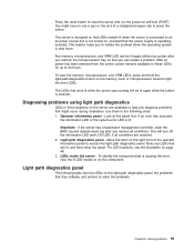
.... To identify the component that is pressed. You might occur during installation. To view the memory, microprocessor, and VRM LEDs, press and hold the light-path-diagnostics button on the memory card, or microprocessor board to 24 hours. The LEDs that were lit while the server was... LED is operating correctly. Move the latch on the right front of a straightened paper clip to access the light path diagnostics panel. Any memory, microprocessor, and VRM LED can isolate a problem. Operator information panel - This feature helps you can be lit again while the button is...
.... To identify the component that is pressed. You might occur during installation. To view the memory, microprocessor, and VRM LEDs, press and hold the light-path-diagnostics button on the memory card, or microprocessor board to 24 hours. The LEDs that were lit while the server was... LED is operating correctly. Move the latch on the right front of a straightened paper clip to access the light path diagnostics panel. Any memory, microprocessor, and VRM LED can isolate a problem. Operator information panel - This feature helps you can be lit again while the button is...
User Manual
Page 76
... or DIMM. 2. I /O board 3. Replace the components listed in step 2 one at a time, in the order shown, restarting the server each time. 64 IBM xSeries 366 Type 8863: Installation Guide Reinstall the removed drive. 2. I /O board 3. Memory board b. Reseat the Remote Supervisor Adapter II SlimLine. Supervisor Adapter II SlimLine. 2. Update the firmware for that LED. 4. Remove the...
... or DIMM. 2. I /O board 3. Replace the components listed in step 2 one at a time, in the order shown, restarting the server each time. 64 IBM xSeries 366 Type 8863: Installation Guide Reinstall the removed drive. 2. I /O board 3. Memory board b. Reseat the Remote Supervisor Adapter II SlimLine. Supervisor Adapter II SlimLine. 2. Update the firmware for that LED. 4. Remove the...


