Hardware Maintenance Manual
Page 8
Installing options 33 Major components of the xSeries 342 server 33 System board layout 34 System board options connectors 34 System board internal cable connectors ...47 Internal drive bays 47 SCSI drives 48 SCSI IDs 48 Hot-swap drive installation 49 Non-hot-swap drive installation 50 Memory modules 51 Microprocessor installation 53 Microprocessor installation in Models 1RX, 2RX, 4RX, 1TG, 2TG, 4TG 54 Microprocessor installation in ...disk drive backplane assembly 79 Power supply backplane 80 AC distribution box 81 vi Hardware Maintenance Manual: xSeries 342 Type 8669
Installing options 33 Major components of the xSeries 342 server 33 System board layout 34 System board options connectors 34 System board internal cable connectors ...47 Internal drive bays 47 SCSI drives 48 SCSI IDs 48 Hot-swap drive installation 49 Non-hot-swap drive installation 50 Memory modules 51 Microprocessor installation 53 Microprocessor installation in Models 1RX, 2RX, 4RX, 1TG, 2TG, 4TG 54 Microprocessor installation in ...disk drive backplane assembly 79 Power supply backplane 80 AC distribution box 81 vi Hardware Maintenance Manual: xSeries 342 Type 8669
Hardware Maintenance Manual
Page 11
..., mouse (pointing device), diskette drive, serial ports, and hard drives. General checkout The server diagnostic programs are stored in upgradable read-only memory (ROM) on page 12. © Copyright IBM Corp. 2000, 2001 1 Also, if you cannot determine whether a problem is additionally attached to the storage unit. v One or more systems sharing...
..., mouse (pointing device), diskette drive, serial ports, and hard drives. General checkout The server diagnostic programs are stored in upgradable read-only memory (ROM) on page 12. © Copyright IBM Corp. 2000, 2001 1 Also, if you cannot determine whether a problem is additionally attached to the storage unit. v One or more systems sharing...
Hardware Maintenance Manual
Page 13
... the xSeries 342: Microprocessor: v Intel® Pentium® III v 256 KB or 512 KB Level-2 cache v Supports up -to-date information about the server model and other IBM server products at the following World Wide Web address: http://www.ibm.com/eserver/xseries. Performance...hot-swap fans Video: v S3 video controller v Compatible with SVGA and VGA v 8 MB video memory © Copyright IBM Corp. 2000, 2001 3 General information The IBM xSeries 342 server is ideally suited for networking environments that supports symmetric multiprocessing (SMP). It is a high-performance server...
... the xSeries 342: Microprocessor: v Intel® Pentium® III v 256 KB or 512 KB Level-2 cache v Supports up -to-date information about the server model and other IBM server products at the following World Wide Web address: http://www.ibm.com/eserver/xseries. Performance...hot-swap fans Video: v S3 video controller v Compatible with SVGA and VGA v 8 MB video memory © Copyright IBM Corp. 2000, 2001 3 General information The IBM xSeries 342 server is ideally suited for networking environments that supports symmetric multiprocessing (SMP). It is a high-performance server...
Hardware Maintenance Manual
Page 15
... applications. v Optional redundant power capability You can view the system health; v IBM integrated system management processor (ISMP) The integrated system management processor provides environmental monitoring for... 3.3 V, 168-pin, 8-byte, registered, synchronous-dynamic-random access memory (SDRAM) dual inline memory modules (DIMMs). When environmental conditions exceed thresholds or when system components fail...the server. v Redundant network-interface card General information 5 Server features The xSeries 342 is available to add three additional drives. The server supports up to ...
... applications. v Optional redundant power capability You can view the system health; v IBM integrated system management processor (ISMP) The integrated system management processor provides environmental monitoring for... 3.3 V, 168-pin, 8-byte, registered, synchronous-dynamic-random access memory (SDRAM) dual inline memory modules (DIMMs). When environmental conditions exceed thresholds or when system components fail...the server. v Redundant network-interface card General information 5 Server features The xSeries 342 is available to add three additional drives. The server supports up to ...
Hardware Maintenance Manual
Page 16
...a variety of application programs for nonvital alerts 6 Hardware Maintenance Manual: xSeries 342 Type 8669 and that the server is an abbreviated list of the RAS features that... the server supports. These factors help you set up the server and install the network operating system (NOS). that should a failure occur, you want to use it; v IBM... v Power-on the SCSI and PCI buses v Error checking and correcting (ECC) memory v Redundant hot-swap power supply option v Redundant hot-swap cooling v Redundant Ethernet ...
...a variety of application programs for nonvital alerts 6 Hardware Maintenance Manual: xSeries 342 Type 8669 and that the server is an abbreviated list of the RAS features that... the server supports. These factors help you set up the server and install the network operating system (NOS). that should a failure occur, you want to use it; v IBM... v Power-on the SCSI and PCI buses v Error checking and correcting (ECC) memory v Redundant hot-swap power supply option v Redundant hot-swap cooling v Redundant Ethernet ...

Hardware Maintenance Manual
Page 21
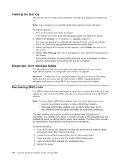
... See the following illustration shows the LEDs on the diagnostics panel on page 92. See "Light path diagnostics" on identifying © Copyright IBM Corp. 2000, 2001 11 These LEDs are part of system error that occurred. Light path diagnostics You can identify the type of the ...of a problem. The server is designed so that any LEDs that might occur with some common problems that are stored in upgradable read-only memory (ROM) on self-test (POST) generates beep codes and messages to indicate successful test completion or the detection of system error that occurred...
... See the following illustration shows the LEDs on the diagnostics panel on page 92. See "Light path diagnostics" on identifying © Copyright IBM Corp. 2000, 2001 11 These LEDs are part of system error that occurred. Light path diagnostics You can identify the type of the ...of a problem. The server is designed so that any LEDs that might occur with some common problems that are stored in upgradable read-only memory (ROM) on self-test (POST) generates beep codes and messages to indicate successful test completion or the detection of system error that occurred...

Hardware Maintenance Manual
Page 23
... using the SCSISelect Utility, use the following might be causing the problem. These entries occur prior to take. v The last device in upgradable read-only memory (ROM) on the system board.
... using the SCSISelect Utility, use the following might be causing the problem. These entries occur prior to take. v The last device in upgradable read-only memory (ROM) on the system board.

Hardware Maintenance Manual
Page 25
... the top of the screen. Warning This result occurs when a possible problem is reported during the diagnostic test, such as system configuration, memory contents, interrupt request (IRQ) use, direct memory access (DMA) use to the server, you can view server configuration information (such as when a device that is set , you left off...
... the top of the screen. Warning This result occurs when a possible problem is reported during the diagnostic test, such as system configuration, memory contents, interrupt request (IRQ) use, direct memory access (DMA) use to the server, you can view server configuration information (such as when a device that is set , you left off...
Hardware Maintenance Manual
Page 26
...the BIOS flash diskette into the diskette drive. 5. Restart the server. 16 Hardware Maintenance Manual: xSeries 342 Type 8669 Type in the tables, make the appropriate selections. When you can obtain a BIOS flash diskette...off the server and peripheral devices and disconnect all external cables and power cords; The flash memory of the screen. 4. Place a jumper on the system board. 3. Viewing the test... is cleared. When the message F2 for it. Turn off the power to http://www.ibm.com/pc/support/ and make sure that cannot be overwritten. When the Diagnostic Programs screen...
...the BIOS flash diskette into the diskette drive. 5. Restart the server. 16 Hardware Maintenance Manual: xSeries 342 Type 8669 Type in the tables, make the appropriate selections. When you can obtain a BIOS flash diskette...off the server and peripheral devices and disconnect all external cables and power cords; The flash memory of the screen. 4. Place a jumper on the system board. 3. Viewing the test... is cleared. When the message F2 for it. Turn off the power to http://www.ibm.com/pc/support/ and make sure that cannot be overwritten. When the Diagnostic Programs screen...
Hardware Maintenance Manual
Page 34
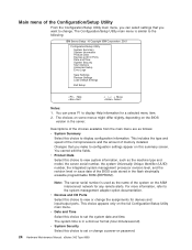
...adapter option documentation. This includes the type and speed of the microprocessors and the amount of memory installed. For more information, refer to the following: IBM Server Setup - © Copyright IBM Corporation 2001 Configuration/Setup Utility · System Summary · System Information · Product Data... programmable ROM (EEPROM). Changes that you want to set or change a power-on password. 24 Hardware Maintenance Manual: xSeries 342 Type 8669 v Date and Time Select this summary screen. This choice appears only on the ASM interconnect network for devices and input...
...adapter option documentation. This includes the type and speed of the microprocessors and the amount of memory installed. For more information, refer to the following: IBM Server Setup - © Copyright IBM Corporation 2001 Configuration/Setup Utility · System Summary · System Information · Product Data... programmable ROM (EEPROM). Changes that you want to set or change a power-on password. 24 Hardware Maintenance Manual: xSeries 342 Type 8669 v Date and Time Select this summary screen. This choice appears only on the ASM interconnect network for devices and input...
Hardware Maintenance Manual
Page 35
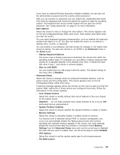
... for a startable diskette in the master boot record at startup. See "Using passwords" on this choice to do so by an IBM authorized service representative. - Start options take effect when you can define a startup sequence that the system might malfunction if these options are... configured incorrectly. You can enable a virus-detection test that control features of memory. The default setting for changes in the diskette drive; A warning message appears above the choices on page 27 for all microprocessors. -...
... for a startable diskette in the master boot record at startup. See "Using passwords" on this choice to do so by an IBM authorized service representative. - Start options take effect when you can define a startup sequence that the system might malfunction if these options are... configured incorrectly. You can enable a virus-detection test that control features of memory. The default setting for changes in the diskette drive; A warning message appears above the choices on page 27 for all microprocessors. -...

Hardware Maintenance Manual
Page 43
... fan Air baffle Memory module Fan sink Microprocessor Terminator card System board Filler panel for drive bay Hot-swap hard disk drive Hot-swap power supply Filler panel for device bay Filler panel for power supply bay © Copyright IBM Corp. 2000, 2001 33 Major components of the xSeries 342 server The orange color...
... fan Air baffle Memory module Fan sink Microprocessor Terminator card System board Filler panel for drive bay Hot-swap hard disk drive Hot-swap power supply Filler panel for device bay Filler panel for power supply bay © Copyright IBM Corp. 2000, 2001 33 Major components of the xSeries 342 server The orange color...

Hardware Maintenance Manual
Page 49
.... Nonmaskable interrupt occurred. A VRM failure occurred. MEM PS1 CPU PS2 PCI A PS3 PCI B NON PCI C OVER VRM NMI DASD TEMP SP FAN REMIND Description A memory failure occurred. This LED is turned on by the integrated system management processor. This LED is turned on by the hardware when either of the... two Light Path LEDs located near the memory (DIMM) are turned on when any of over temperature (such as CPUx, CPU, DASD LEDs). Error occurred on an adapter in PCI slot 4 or 5...
.... Nonmaskable interrupt occurred. A VRM failure occurred. MEM PS1 CPU PS2 PCI A PS3 PCI B NON PCI C OVER VRM NMI DASD TEMP SP FAN REMIND Description A memory failure occurred. This LED is turned on by the integrated system management processor. This LED is turned on by the hardware when either of the... two Light Path LEDs located near the memory (DIMM) are turned on when any of over temperature (such as CPUx, CPU, DASD LEDs). Error occurred on an adapter in PCI slot 4 or 5...

Hardware Maintenance Manual
Page 51
... has either a drive or a filler panel installed. v The fans are routed according to the instructions provided with the adapters (ensure that protects the processor and memory area is removed for no longer that is turned on: v Avoid loose-fitting clothing on with power on the server) that cables are met. See...
... has either a drive or a filler panel installed. v The fans are routed according to the instructions provided with the adapters (ensure that protects the processor and memory area is removed for no longer that is turned on: v Avoid loose-fitting clothing on with power on the server) that cables are met. See...

Hardware Maintenance Manual
Page 52
... the option down. Removing the cover and bezel The following sections describe how to remove the cover and bezel. Statement 1: 42 Hardware Maintenance Manual: xSeries 342 Type 8669 v Always handle components carefully. Locations The following section describes how to remove and/or install certain components inside the server. Review the information in on... place the option on page 40. 2. If you begin" on the server's covers or any exposed circuitry. Never touch any metal surface. Handle adapters, the memory board, and memory modules (DIMMs) by the edges.
... the option down. Removing the cover and bezel The following sections describe how to remove the cover and bezel. Statement 1: 42 Hardware Maintenance Manual: xSeries 342 Type 8669 v Always handle components carefully. Locations The following section describes how to remove and/or install certain components inside the server. Review the information in on... place the option on page 40. 2. If you begin" on the server's covers or any exposed circuitry. Never touch any metal surface. Handle adapters, the memory board, and memory modules (DIMMs) by the edges.
Hardware Maintenance Manual
Page 61
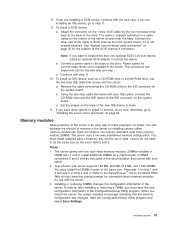
...server cover and bezel" on page 35 for non-hot-swap drives come installed in slots 2 and 3. Memory modules Adding memory to be inserted only one way. Install additional DIMMs as a matched pair in DIMM connectors 2 and ... 1-drop SCSI cable for use the two-drop IDE cable that comes with step 11 10. c. Your xSeries 342 server supports 128 MB, 256 MB, 512 MB, and 1 GB DIMMs. You must save the new ... to the IDE connector on the World Wide Web at http://www.ibm.com/pc/compat for information about memory modules for the non-hot-swap drive bays to SCSI channel A on the ...
...server cover and bezel" on page 35 for non-hot-swap drives come installed in slots 2 and 3. Memory modules Adding memory to be inserted only one way. Install additional DIMMs as a matched pair in DIMM connectors 2 and ... 1-drop SCSI cable for use the two-drop IDE cable that comes with step 11 10. c. Your xSeries 342 server supports 128 MB, 256 MB, 512 MB, and 1 GB DIMMs. You must save the new ... to the IDE connector on the World Wide Web at http://www.ibm.com/pc/compat for information about memory modules for the non-hot-swap drive bays to SCSI channel A on the ...

Hardware Maintenance Manual
Page 62
...: 52 Hardware Maintenance Manual: xSeries 342 Type 8669 Touch the static-protective package containing the DIMM to any unpainted metal surface on page 42.) 4. Review the information in slots 2 and 3. Attention: To avoid breaking the retaining clips or damaging the DIMM connectors, handle the clips gently. 5. You must install memory in matched pairs: the...
...: 52 Hardware Maintenance Manual: xSeries 342 Type 8669 Touch the static-protective package containing the DIMM to any unpainted metal surface on page 42.) 4. Review the information in slots 2 and 3. Attention: To avoid breaking the retaining clips or damaging the DIMM connectors, handle the clips gently. 5. You must install memory in matched pairs: the...

Hardware Maintenance Manual
Page 94
...comparing CMOS memory size against actual) 1. Install or reseat the memory modules, then do a 3 boot reset. (See "Using the Configuration/Setup Utility program" on page 25) 2. System Board 84 Hardware Maintenance Manual: xSeries 342 Type 8669 System Board... Board 3-2-2 (Parallel port failed) 1. Adapter 3. System Board 2-3-1 (Screen initialization failed) 1. System Board 3. DASD Backplane 5. see ″Memory Settings″ on page 23.) 2. Keyboard 2-2-3 (CMOS power failure and checksum checks failed) 1. Battery 2. System Board operable) 3-1-1 (Timer...
...comparing CMOS memory size against actual) 1. Install or reseat the memory modules, then do a 3 boot reset. (See "Using the Configuration/Setup Utility program" on page 25) 2. System Board 84 Hardware Maintenance Manual: xSeries 342 Type 8669 System Board... Board 3-2-2 (Parallel port failed) 1. Adapter 3. System Board 2-3-1 (Screen initialization failed) 1. System Board 3. DASD Backplane 5. see ″Memory Settings″ on page 23.) 2. Keyboard 2-2-3 (CMOS power failure and checksum checks failed) 1. Battery 2. System Board operable) 3-1-1 (Timer...

Hardware Maintenance Manual
Page 99
...) cable between Remote Supervisor Adapter (I2C Bus Error(s). Remote Supervisor Adapter 166-342-000 System Management: Failed 1. These include other error conditions and retry. Potential FRUs: Memory DIMMs, system board.) 2. Reseat I2C cables between Power Backplane and planar (... Failed 1. Potential FRUs: LED front panel, system board.) 2. System board 166-201-003 System Management: Failed 1. Potential FRUs: Memory 2. Reseat processors DIMMs, CPUs, system board.) 3. Processors 5. After restarting, ASM communication was lost. Unplug and cold 2. Ensure the...
...) cable between Remote Supervisor Adapter (I2C Bus Error(s). Remote Supervisor Adapter 166-342-000 System Management: Failed 1. These include other error conditions and retry. Potential FRUs: Memory DIMMs, system board.) 2. Reseat I2C cables between Power Backplane and planar (... Failed 1. Potential FRUs: LED front panel, system board.) 2. System board 166-201-003 System Management: Failed 1. Potential FRUs: Memory 2. Reseat processors DIMMs, CPUs, system board.) 3. Processors 5. After restarting, ASM communication was lost. Unplug and cold 2. Ensure the...

Hardware Maintenance Manual
Page 100
... Fixed Disk 2 Note: If RAID is configured, the fixed disk number refers to the RAID logical array 90 Hardware Maintenance Manual: xSeries 342 Type 8669 Operator Information Panel 2. Power Switch Assembly 3. SCSI Backplane Cable 3. Microprocessor 2 206-XXX-000 (Failed Diskette Drive test) 1. System ...on page 25) 1. Fan(s) 2. System Board 180-XXX-003 (Failed System Board LED test) 1. SCSI Backplane 2. System Board 201-XXX-0NN (Failed Memory test, see error text) 1. DIMM Location slots 1-4 where NN = DIMM location. Note: NN=1=DIMM 1 =2=DIMM 2 =3=DIMM 3 =4=DIMM 4 2. ...
... Fixed Disk 2 Note: If RAID is configured, the fixed disk number refers to the RAID logical array 90 Hardware Maintenance Manual: xSeries 342 Type 8669 Operator Information Panel 2. Power Switch Assembly 3. SCSI Backplane Cable 3. Microprocessor 2 206-XXX-000 (Failed Diskette Drive test) 1. System ...on page 25) 1. Fan(s) 2. System Board 180-XXX-003 (Failed System Board LED test) 1. SCSI Backplane 2. System Board 201-XXX-0NN (Failed Memory test, see error text) 1. DIMM Location slots 1-4 where NN = DIMM location. Note: NN=1=DIMM 1 =2=DIMM 2 =3=DIMM 3 =4=DIMM 4 2. ...


