User Manual
Page 7
Introduction 1 Related documentation 1 Notices and statements used in bay 5, 6, or 7 36 © Copyright IBM Corp. 2004, 2007 v Diagnostics 13 General checkout 13 Diagnostic tools overview 15 Power-on self-test 15 POST beep codes 15 ...xSeries 206 Type 8482 and 8487 server 25 Removing the side cover 26 Removing the bezel 27 Removing and installing the support bracket 28 Installing a memory module 29 Installing a drive 31 Installing a drive in bay 2 or 4 32 Replacing the CD-ROM drive in bay 2 35 Replacing the diskette drive in bay 3 36 Installing a hot-swap SCSI hard disk drive...
Introduction 1 Related documentation 1 Notices and statements used in bay 5, 6, or 7 36 © Copyright IBM Corp. 2004, 2007 v Diagnostics 13 General checkout 13 Diagnostic tools overview 15 Power-on self-test 15 POST beep codes 15 ...xSeries 206 Type 8482 and 8487 server 25 Removing the side cover 26 Removing the bezel 27 Removing and installing the support bracket 28 Installing a memory module 29 Installing a drive 31 Installing a drive in bay 2 or 4 32 Replacing the CD-ROM drive in bay 2 35 Replacing the diskette drive in bay 3 36 Installing a hot-swap SCSI hard disk drive...

User Manual
Page 8
... 96 Undetermined problems 97 Problem determination tips 98 vi xSeries 206 Type 8482 and 8487: Hardware Maintenance Manual and Troubleshooting Guide SCSI IDs for hot-swap hard disk drives 39 Installing a non-hot-swap SCSI hard disk drive in bay 4, 5, 6, or 7 . . . . . 39 Installing a simple-swap Serial ATA hard disk drive in bay 5, 6, or 7 . . . . 41 Power and signal cables for...
... 96 Undetermined problems 97 Problem determination tips 98 vi xSeries 206 Type 8482 and 8487: Hardware Maintenance Manual and Troubleshooting Guide SCSI IDs for hot-swap hard disk drives 39 Installing a non-hot-swap SCSI hard disk drive in bay 4, 5, 6, or 7 . . . . . 39 Installing a simple-swap Serial ATA hard disk drive in bay 5, 6, or 7 . . . . 41 Power and signal cables for...
User Manual
Page 13
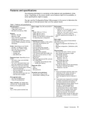
... output vary depending on the system board Fans: Two or three speed-controlled fans Environment: v Air temperature: - Introduction 3 hard disk drive bays with one hard disk drive installed - Compatible with SVGA and VGA - 16 MB video memory Diagnostic LEDs: v Fans v Memory v Microprocessor Acoustical noise ... ATI 7000M video - Minimum: 100 V ac - Maximum: 240 V ac v Input kilovolt-amperes (kVA) approximately: - Table 1. removable-media drive bays (one hard disk drive installed Power supply: One 340 watt (90-240 V ac) Size: v Height: 448 mm (17.25 in.) v Depth: 483 mm ...
... output vary depending on the system board Fans: Two or three speed-controlled fans Environment: v Air temperature: - Introduction 3 hard disk drive bays with one hard disk drive installed - Compatible with SVGA and VGA - 16 MB video memory Diagnostic LEDs: v Fans v Memory v Microprocessor Acoustical noise ... ATI 7000M video - Minimum: 100 V ac - Maximum: 240 V ac v Input kilovolt-amperes (kVA) approximately: - Table 1. removable-media drive bays (one hard disk drive installed Power supply: One 340 watt (90-240 V ac) Size: v Height: 448 mm (17.25 in.) v Depth: 483 mm ...
User Manual
Page 14
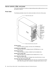
...it indicates that the drive is in use . When this LED is lit, it indicates that the diskette drive is in use . 4 xSeries 206 Type 8482 and 8487: Hardware Maintenance Manual and Troubleshooting Guide Hard disk drive activity LED When ...this LED is lit, it indicates that the CD-ROM drive is in use . CD-ROM drive activity LED When this LED is flashing, it indicates that a hard disk drive is in use . Hot-swap hard disk drive...
...it indicates that the drive is in use . When this LED is lit, it indicates that the diskette drive is in use . 4 xSeries 206 Type 8482 and 8487: Hardware Maintenance Manual and Troubleshooting Guide Hard disk drive activity LED When ...this LED is lit, it indicates that the CD-ROM drive is in use . CD-ROM drive activity LED When this LED is flashing, it indicates that a hard disk drive is in use . Hot-swap hard disk drive...
User Manual
Page 15
.... USB ports Connect a USB device to help isolate the error. When the drive is connected to an ac power source (standby mode). Hot-swap hard disk drive status LED On some server models, each hot-swap hard disk drive has a status LED. Power-control button Press this LED is lit, it ... 72 for a drive is lit continuously, that the drive is faulty. If the status LED for additional information. When this LED is on the Ethernet connector on the Ethernet connector. When this button to turn the server on and off and still connected to an optional ServeRAID™ controller, a ...
.... USB ports Connect a USB device to help isolate the error. When the drive is connected to an ac power source (standby mode). Hot-swap hard disk drive status LED On some server models, each hot-swap hard disk drive has a status LED. Power-control button Press this LED is lit, it ... 72 for a drive is lit continuously, that the drive is faulty. If the status LED for additional information. When this LED is on the Ethernet connector on the Ethernet connector. When this button to turn the server on and off and still connected to an optional ServeRAID™ controller, a ...
User Manual
Page 23
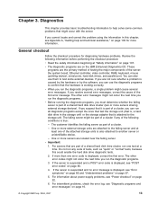
... the storage unit (that is, a hard disk drive in this could enable the hard disk drive diagnostic tests. 2. One or more servers sharing external storage devices). Do not run one error code is displayed, see "Power checkout" on the IBM Enhanced Diagnostics CD. If the server is..., correct the cause of the server: the system board, Ethernet controller, video controller, RAM, keyboard, mouse (pointing device), serial ports, hard disk drives, and parallel port. v When you can run the diagnostic programs, a single problem might occur with the server. For information about power-...
... the storage unit (that is, a hard disk drive in this could enable the hard disk drive diagnostic tests. 2. One or more servers sharing external storage devices). Do not run one error code is displayed, see "Power checkout" on the IBM Enhanced Diagnostics CD. If the server is..., correct the cause of the server: the system board, Ethernet controller, video controller, RAM, keyboard, mouse (pointing device), serial ports, hard disk drives, and parallel port. v When you can run the diagnostic programs, a single problem might occur with the server. For information about power-...
User Manual
Page 27
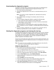
..., press the F1 key. 4. The following sections describe the diagnostic procedure for the server to a hard disk directory (not to a diskette). Using the diagnostics CD To start the IBM Enhanced Diagnostics using the CD, complete the following steps: 1. Turn on the screen to run independently ... CD. then, turn on the xSeries 206 server only when the server has an optional Remote Supervisor Adapter II. When you generally use a blank CD in the CD-ROM drive. 10. Select CD-ROM as the first startup device. Insert the IBM Enhanced Diagnostics CD in conjunction with the...
..., press the F1 key. 4. The following sections describe the diagnostic procedure for the server to a hard disk directory (not to a diskette). Using the diagnostics CD To start the IBM Enhanced Diagnostics using the CD, complete the following steps: 1. Turn on the screen to run independently ... CD. then, turn on the xSeries 206 server only when the server has an optional Remote Supervisor Adapter II. When you generally use a blank CD in the CD-ROM drive. 10. Select CD-ROM as the first startup device. Insert the IBM Enhanced Diagnostics CD in conjunction with the...

User Manual
Page 28
...on page 83. The test-log data is maintained only while the diagnostic programs are active. Insert the IBM Enhanced Diagnostics diskette into the external USB diskette drive. 3. Follow the instructions on all attached devices; If the hardware passes the Enhanced Diagnostics but the problem...tables For descriptions of this . When you suspect a software problem, refer to the hard disk. If you exit from the diagnostic programs, the test log is not installed. 18 xSeries 206 Type 8482 and 8487: Hardware Maintenance Manual and Troubleshooting Guide 11. You can save the test log...
...on page 83. The test-log data is maintained only while the diagnostic programs are active. Insert the IBM Enhanced Diagnostics diskette into the external USB diskette drive. 3. Follow the instructions on all attached devices; If the hardware passes the Enhanced Diagnostics but the problem...tables For descriptions of this . When you suspect a software problem, refer to the hard disk. If you exit from the diagnostic programs, the test log is not installed. 18 xSeries 206 Type 8482 and 8487: Hardware Maintenance Manual and Troubleshooting Guide 11. You can save the test log...
User Manual
Page 38
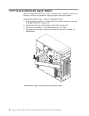
... a 45° angle. 4. To reinstall the support bracket, reverse the previous steps. 28 xSeries 206 Type 8482 and 8487: Hardware Maintenance Manual and Troubleshooting Guide Removing and installing the support bracket When working with some devices, such as hard disk drives, adapters, and memory modules, you must first remove the support bracket to remove the...
... a 45° angle. 4. To reinstall the support bracket, reverse the previous steps. 28 xSeries 206 Type 8482 and 8487: Hardware Maintenance Manual and Troubleshooting Guide Removing and installing the support bracket When working with some devices, such as hard disk drives, adapters, and memory modules, you must first remove the support bracket to remove the...
User Manual
Page 41
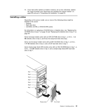
... the support bracket (see "Replacing the CD-ROM drive in bay 2" on page 35 and "Replacing the diskette drive in the server: v Diskette v Hard disk drive v CD-ROM, CD-RW, or DVD/CD-RW combo For information on replacing a CD-ROM drive or diskette drive, see "Removing and installing the support bracket" on... 2 Bay 3 Bay 4 Bay 5 Bay 6 Bay 7 Recess area Door hatch Chapter 4. Some hot-swap models come with an IDE CD-ROM drive in bay 1, a 3.5-in., 1.44 MB diskette drive in bay 3, and a simple-swap Serial ATA hard disk drive in bay 7. Some simple-swap Serial ATA models come with an IDE CD-ROM...
... the support bracket (see "Replacing the CD-ROM drive in bay 2" on page 35 and "Replacing the diskette drive in the server: v Diskette v Hard disk drive v CD-ROM, CD-RW, or DVD/CD-RW combo For information on replacing a CD-ROM drive or diskette drive, see "Removing and installing the support bracket" on... 2 Bay 3 Bay 4 Bay 5 Bay 6 Bay 7 Recess area Door hatch Chapter 4. Some hot-swap models come with an IDE CD-ROM drive in bay 1, a 3.5-in., 1.44 MB diskette drive in bay 3, and a simple-swap Serial ATA hard disk drive in bay 7. Some simple-swap Serial ATA models come with an IDE CD-ROM...
User Manual
Page 42
...www.ibm.com/pc/support/. v Check the instructions that comes with the drive. Complete the following steps to the CD-ROM drive in bay 1 can be cabled to install a drive in...drives, tape drives, CD-ROM, CD-RW, and DVD drives are installing a drive that contains a laser, observe the following safety precaution. 32 xSeries 206 Type 8482 and 8487: Hardware Maintenance Manual and Troubleshooting Guide drive... with the drive. bay, you must consider when installing a hard disk drive: v Read the safety information beginning at "Safety information" on page 107. 2. Installing a drive in bay ...
...www.ibm.com/pc/support/. v Check the instructions that comes with the drive. Complete the following steps to the CD-ROM drive in bay 1 can be cabled to install a drive in...drives, tape drives, CD-ROM, CD-RW, and DVD drives are installing a drive that contains a laser, observe the following safety precaution. 32 xSeries 206 Type 8482 and 8487: Hardware Maintenance Manual and Troubleshooting Guide drive... with the drive. bay, you must consider when installing a hard disk drive: v Read the safety information beginning at "Safety information" on page 107. 2. Installing a drive in bay ...

User Manual
Page 46
... clip from your hardware. v All hot-swap drives being used in each drive bay. Before you install a hot-swap hard disk drive, read the following steps to operate at "Safety information" on page 24, and the safety information beginning at the speed of the slowest drive. 36 xSeries 206 Type 8482 and 8487: Hardware Maintenance Manual and Troubleshooting...
... clip from your hardware. v All hot-swap drives being used in each drive bay. Before you install a hot-swap hard disk drive, read the following steps to operate at "Safety information" on page 24, and the safety information beginning at the speed of the slowest drive. 36 xSeries 206 Type 8482 and 8487: Hardware Maintenance Manual and Troubleshooting...
User Manual
Page 47
... controls the SCSI IDs for installing a hard disk drive. v Each hot-swap drive has two LEDs: the hard disk drive activity LED and the hard disk drive status LED. When the green hard disk drive activity LED is flashing, it indicates that the controller is accessing the hard disk drive. Hard disk drive activity LED (green) Hard disk drive status LED (amber) SCSI hot-swap...
... controls the SCSI IDs for installing a hard disk drive. v Each hot-swap drive has two LEDs: the hard disk drive activity LED and the hard disk drive status LED. When the green hard disk drive activity LED is flashing, it indicates that the controller is accessing the hard disk drive. Hard disk drive activity LED (green) Hard disk drive status LED (amber) SCSI hot-swap...

User Manual
Page 48
...guide rails in the hot-swap bay: a. c. Note: If your finger into the drive bay until the server is , perpendicular to any unpainted metal surface on the IBM ServeRAID Support CD for additional information about RAID operation and complete instructions for RAID operation using ...Install the hard disk drive in the bay. Filler panel Drive tray assembly Drive bay lock-bar Drive tray handle (in open (that the tray handle is configured for using an optional ServeRAID controller, you are installing additional hot-swap hard disk drives, do so now. 38 xSeries 206 Type 8482 and 8487:...
...guide rails in the hot-swap bay: a. c. Note: If your finger into the drive bay until the server is , perpendicular to any unpainted metal surface on the IBM ServeRAID Support CD for additional information about RAID operation and complete instructions for RAID operation using ...Install the hard disk drive in the bay. Filler panel Drive tray assembly Drive bay lock-bar Drive tray handle (in open (that the tray handle is configured for using an optional ServeRAID controller, you are installing additional hot-swap hard disk drives, do so now. 38 xSeries 206 Type 8482 and 8487:...
User Manual
Page 49
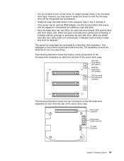
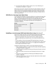
...26). 4. If the amber hard disk drive status LED for each hot-swap hard disk drive is operating correctly. If the green hard disk drive activity LED is flashing, it disengages from the fans. SCSI IDs for hot-swap hard disk drives The hot-swap-drive backplane controls the SCSI IDs for..." on page 107. 2. If you install the drive. Device AIC 7901 controller (mini-PCI-X slot) Hot-swap backplane Drive bay 7 Drive bay 6 Drive bay 5 SCSI ID 7 9 12 13 14 Installing a non-hot-swap SCSI hard disk drive in hot-swap hard disk drive models. Remove the support bracket (see "Removing the...
...26). 4. If the amber hard disk drive status LED for each hot-swap hard disk drive is operating correctly. If the green hard disk drive activity LED is flashing, it disengages from the fans. SCSI IDs for hot-swap hard disk drives The hot-swap-drive backplane controls the SCSI IDs for..." on page 107. 2. If you install the drive. Device AIC 7901 controller (mini-PCI-X slot) Hot-swap backplane Drive bay 7 Drive bay 6 Drive bay 5 SCSI ID 7 9 12 13 14 Installing a non-hot-swap SCSI hard disk drive in hot-swap hard disk drive models. Remove the support bracket (see "Removing the...
User Manual
Page 51
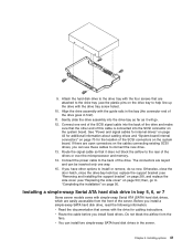
... the SCSI connectors on page 50. v You can install two simple-swap SATA hard disk drives in the bay (the connector end of the drives or over the microprocessor and memory. 14. Installing a simple-swap Serial ATA hard disk drive in bay 5, 6, or 7 Some server models come with the guide rails in... the server. Align the drive assembly with simple-swap Serial ATA (SATA) hard disk drives, which are attached to the drive tray (use these cables to install or remove, do so now. then, go . 12. Chapter 4. Connect one way. 15. ...
... the SCSI connectors on page 50. v You can install two simple-swap SATA hard disk drives in the bay (the connector end of the drives or over the microprocessor and memory. 14. Installing a simple-swap Serial ATA hard disk drive in bay 5, 6, or 7 Some server models come with the guide rails in... the server. Align the drive assembly with simple-swap Serial ATA (SATA) hard disk drives, which are attached to the drive tray (use these cables to install or remove, do so now. then, go . 12. Chapter 4. Connect one way. 15. ...

User Manual
Page 52
... 1 Bay 2 Bay 3 Bay 4 Bay 5 Bay 6 Bay 7 Recess area Door hatch 42 xSeries 206 Type 8482 and 8487: Hardware Maintenance Manual and Troubleshooting Guide See "Installing a drive in bay 4. v Install simple-swap SATA hard disk drives in the server. Complete the following steps to install a hard disk drive in bay 2 or 4" on page 32 for cabling instructions. Note: You...
... 1 Bay 2 Bay 3 Bay 4 Bay 5 Bay 6 Bay 7 Recess area Door hatch 42 xSeries 206 Type 8482 and 8487: Hardware Maintenance Manual and Troubleshooting Guide See "Installing a drive in bay 4. v Install simple-swap SATA hard disk drives in the server. Complete the following steps to install a hard disk drive in bay 2 or 4" on page 32 for cabling instructions. Note: You...
User Manual
Page 53
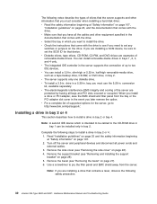
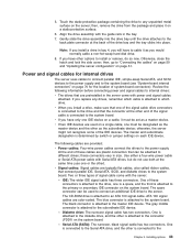
... into the drive bay until the drive attaches to an ATA 100 signal cable. Power and signal cables for the location of the IDE devices. v When you would normally cable a non-hot-swap hard disk drive. 8. At the end of these connectors is attached to the drive, one must be designated as... the subordinate device; The CD-ROM drive is attached to the Chapter 4. The gray middle connector is connected to the ...
... into the drive bay until the drive attaches to an ATA 100 signal cable. Power and signal cables for the location of the IDE devices. v When you would normally cable a non-hot-swap hard disk drive. 8. At the end of these connectors is attached to the drive, one must be designated as... the subordinate device; The CD-ROM drive is attached to the Chapter 4. The gray middle connector is connected to the ...
User Manual
Page 54
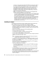
...7000M video adapter are supported if they do not support 3.3 V signaling adapters. v The optional IBM Remote Supervisor Adapter II can install only 32-bit adapters in the 32-bit PCI slots 3 ...round SCSI cable connects external SCSI devices to the optional Remote Supervisor Adapter II. 44 xSeries 206 Type 8482 and 8487: Hardware Maintenance Manual and Troubleshooting Guide For more internal SCSI devices. v...Serial ATA drive comes with five PCI slots. they do not support 5.0 V signaling adapters. An Ultra320 twisted ribbon cable connects the internal Ultra320 SCSI hard disk drive to ...
...7000M video adapter are supported if they do not support 3.3 V signaling adapters. v The optional IBM Remote Supervisor Adapter II can install only 32-bit adapters in the 32-bit PCI slots 3 ...round SCSI cable connects external SCSI devices to the optional Remote Supervisor Adapter II. 44 xSeries 206 Type 8482 and 8487: Hardware Maintenance Manual and Troubleshooting Guide For more internal SCSI devices. v...Serial ATA drive comes with five PCI slots. they do not support 5.0 V signaling adapters. An Ultra320 twisted ribbon cable connects the internal Ultra320 SCSI hard disk drive to ...

User Manual
Page 56
... If any adapters in the server are large or have heavy cables attached to "Completing the installation" on page 44). 46 xSeries 206 Type 8482 and 8487: Hardware Maintenance Manual and Troubleshooting Guide then, go to them, you can remove the rear adapter-retention bracket and ...to the closed (locked) position. If you have installed a full-length adapter, rotate the front adapter-support bracket to control the internal hard disk drives. Cabling an optional SCSI adapter You can also cable a SCSI adapter to connect external SCSI devices. Install the SCSI adapter (see "Removing...
... If any adapters in the server are large or have heavy cables attached to "Completing the installation" on page 44). 46 xSeries 206 Type 8482 and 8487: Hardware Maintenance Manual and Troubleshooting Guide then, go to them, you can remove the rear adapter-retention bracket and ...to the closed (locked) position. If you have installed a full-length adapter, rotate the front adapter-support bracket to control the internal hard disk drives. Cabling an optional SCSI adapter You can also cable a SCSI adapter to connect external SCSI devices. Install the SCSI adapter (see "Removing...


