User Manual
Page 7
... 23 Handling static-sensitive devices 24 Major components of the xSeries 206 Type 8482 and 8487 server 25 Removing the side cover 26 Removing the bezel 27 Removing and installing the support bracket 28 Installing a memory module 29 Installing a drive 31 Installing a drive in ...iii Online support iii Chapter 1. Introduction 1 Related documentation 1 Notices and statements used in bay 5, 6, or 7 36 © Copyright IBM Corp. 2004, 2007 v Configuring the server 9 Using the Configuration/Setup Utility program 9 Using the Adaptec HostRAID configuration programs 10 Using the...
... 23 Handling static-sensitive devices 24 Major components of the xSeries 206 Type 8482 and 8487 server 25 Removing the side cover 26 Removing the bezel 27 Removing and installing the support bracket 28 Installing a memory module 29 Installing a drive 31 Installing a drive in ...iii Online support iii Chapter 1. Introduction 1 Related documentation 1 Notices and statements used in bay 5, 6, or 7 36 © Copyright IBM Corp. 2004, 2007 v Configuring the server 9 Using the Configuration/Setup Utility program 9 Using the Adaptec HostRAID configuration programs 10 Using the...
User Manual
Page 11
... server model, additional documentation might have features that are available from the IBM Web site at http://www.ibm.com/eserver/xseries/. Related documentation This Hardware Maintenance Manual and Troubleshooting Guide is in Portable ... as well as flexible memory and data management. The documentation might be updated occasionally to include information about those features, or technical updates might be included on IBM X-Architecture® technologies....server supports. Introduction The IBM xSeries 206 Type 8482 and 8487 server is ideally suited for installing some options.
... server model, additional documentation might have features that are available from the IBM Web site at http://www.ibm.com/eserver/xseries/. Related documentation This Hardware Maintenance Manual and Troubleshooting Guide is in Portable ... as well as flexible memory and data management. The documentation might be updated occasionally to include information about those features, or technical updates might be included on IBM X-Architecture® technologies....server supports. Introduction The IBM xSeries 206 Type 8482 and 8487 server is ideally suited for installing some options.
User Manual
Page 13
...features installed and the power-management optional features in use the Configuration/Setup Utility program in . Compatible with SVGA and VGA - 16 MB video memory Diagnostic LEDs: v Fans v Memory v Microprocessor Acoustical noise emissions: v Sound power, idling: 5.3 bel v Sound power, operating: 5.5 bel PCI expansion slots: v Two PCI...-X 66 MHz/64-bit v Three PCI 33 MHz/32-bit Video controller: ATI 7000M video controller with 16 MB SDRAM video memory on : 10° to 35°C (50° to 95°F) Altitude: 0 to 20.8 kg (45.8 lb) depending upon configuration...
...features installed and the power-management optional features in use the Configuration/Setup Utility program in . Compatible with SVGA and VGA - 16 MB video memory Diagnostic LEDs: v Fans v Memory v Microprocessor Acoustical noise emissions: v Sound power, idling: 5.3 bel v Sound power, operating: 5.5 bel PCI expansion slots: v Two PCI...-X 66 MHz/64-bit v Three PCI 33 MHz/32-bit Video controller: ATI 7000M video controller with 16 MB SDRAM video memory on : 10° to 35°C (50° to 95°F) Altitude: 0 to 20.8 kg (45.8 lb) depending upon configuration...
User Manual
Page 17
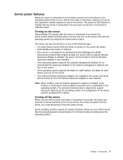
...the server. v If the operating system supports the systems-management software for system resources depends on the operating system, the configuration of memory that contains at least one server with an optional Remote Supervisor Adapter II installed, the server can be turned on from the Remote ... source but is not turned on (standby mode). v If an optional Remote Supervisor Adapter II is installed in any of memory (physical or logical) is installed, some memory is reserved for information about shutting down ; To remove all core logic is shut down the operating system.
...the server. v If the operating system supports the systems-management software for system resources depends on the operating system, the configuration of memory that contains at least one server with an optional Remote Supervisor Adapter II installed, the server can be turned on from the Remote ... source but is not turned on (standby mode). v If an optional Remote Supervisor Adapter II is installed in any of memory (physical or logical) is installed, some memory is reserved for information about shutting down ; To remove all core logic is shut down the operating system.
User Manual
Page 29
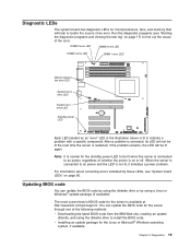
...correcting errors indicated by using the diskette drive to find out the cause of the following methods: v Downloading the latest BIOS code from the IBM Web site, creating an update diskette, and using a Linux or Windows® update package (if available). Updating BIOS code You can .... Run the diagnostic programs (see "System board LEDs" on or off. Diagnostic LEDs The system board has diagnostic LEDs for microprocessors, fans, and memory that will be lit again. After a problem is corrected, its LED will not be lit when the server is connected to indicate a problem with...
...correcting errors indicated by using the diskette drive to find out the cause of the following methods: v Downloading the latest BIOS code from the IBM Web site, creating an update diskette, and using a Linux or Windows® update package (if available). Updating BIOS code You can .... Run the diagnostic programs (see "System board LEDs" on or off. Diagnostic LEDs The system board has diagnostic LEDs for microprocessors, fans, and memory that will be lit again. After a problem is corrected, its LED will not be lit when the server is connected to indicate a problem with...
User Manual
Page 31
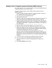
... time without having to use the user password, and use the Configuration/Setup Utility program to pins 2 and 3. 7. Erasing a lost or forgotten password (clearing CMOS memory) This section applies to a power source, keyboard, monitor, and mouse. 10. Remove the side cover and support bracket (see "Removing the side cover" on page...
... time without having to use the user password, and use the Configuration/Setup Utility program to pins 2 and 3. 7. Erasing a lost or forgotten password (clearing CMOS memory) This section applies to a power source, keyboard, monitor, and mouse. 10. Remove the side cover and support bracket (see "Removing the side cover" on page...
User Manual
Page 38
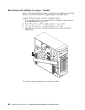
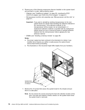
... the support bracket from the server and set the bracket aside. To reinstall the support bracket, reverse the previous steps. 28 xSeries 206 Type 8482 and 8487: Hardware Maintenance Manual and Troubleshooting Guide Disengage the front end of the support bracket at "Safety information" on page ...107. 2. Removing and installing the support bracket When working with some devices, such as hard disk drives, adapters, and memory modules, ...
... the support bracket from the server and set the bracket aside. To reinstall the support bracket, reverse the previous steps. 28 xSeries 206 Type 8482 and 8487: Hardware Maintenance Manual and Troubleshooting Guide Disengage the front end of the support bracket at "Safety information" on page ...107. 2. Removing and installing the support bracket When working with some devices, such as hard disk drives, adapters, and memory modules, ...
User Manual
Page 39
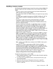
...you install in the DIMM 1 memory connector. Remove the side cover (see "Removing and installing the support bracket" on page 107. 2. You can mix compatible DIMMs from various manufacturers. Installing a memory module The following steps to http://www.ibm.com/us/compat/; For a ...list of DIMMs you install an additional DIMM, it must be installed in DIMM 3 memory connector, the server becomes a dual-channel server. Complete ...
...you install in the DIMM 1 memory connector. Remove the side cover (see "Removing and installing the support bracket" on page 107. 2. You can mix compatible DIMMs from various manufacturers. Installing a memory module The following steps to http://www.ibm.com/us/compat/; For a ...list of DIMMs you install an additional DIMM, it must be installed in DIMM 3 memory connector, the server becomes a dual-channel server. Complete ...
User Manual
Page 40
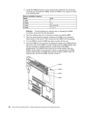
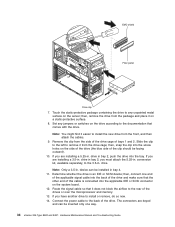
Memory installation sequence DIMMs 1 DIMM 2 DIMMs 3 DIMMs 4 DIMMs Slots 1 1, 3 Not supported 1, 2, 3, 4 Attention: To avoid breaking the retaining clips or damaging the DIMM connectors, open and close ... and, if necessary, remove any unpainted metal surface on the system board. Locate the DIMM connectors on the server. DIMM 4 DIMM 3 DIMM 2 DIMM 1 30 xSeries 206 Type 8482 and 8487: Hardware Maintenance Manual and Troubleshooting Guide Determine the connectors into the locked position when the DIMM is a gap between the DIMM and the...
Memory installation sequence DIMMs 1 DIMM 2 DIMMs 3 DIMMs 4 DIMMs Slots 1 1, 3 Not supported 1, 2, 3, 4 Attention: To avoid breaking the retaining clips or damaging the DIMM connectors, open and close ... and, if necessary, remove any unpainted metal surface on the system board. Locate the DIMM connectors on the server. DIMM 4 DIMM 3 DIMM 2 DIMM 1 30 xSeries 206 Type 8482 and 8487: Hardware Maintenance Manual and Troubleshooting Guide Determine the connectors into the locked position when the DIMM is a gap between the DIMM and the...
User Manual
Page 44
...; conversion kit, available separately, to the rear of the drives or over the microprocessor and memory. 13. Route the signal cable so that it on the system board. 12. then, connect one way. 34 xSeries 206 Type 8482 and 8487: Hardware Maintenance Manual and Troubleshooting Guide then, snap the clip into the bay. If...
...; conversion kit, available separately, to the rear of the drives or over the microprocessor and memory. 13. Route the signal cable so that it on the system board. 12. then, connect one way. 34 xSeries 206 Type 8482 and 8487: Hardware Maintenance Manual and Troubleshooting Guide then, snap the clip into the bay. If...
User Manual
Page 51
... it will go to the rear of the server. Do not block the airflow from the front of the drives or over the microprocessor and memory. 14. Chapter 4.
... it will go to the rear of the server. Do not block the airflow from the front of the drives or over the microprocessor and memory. 14. Chapter 4.
User Manual
Page 84
...the adhesive material on page 29). The power supply has been removed in this time. If replacement adhesive material is removed. 74 xSeries 206 Type 8482 and 8487: Hardware Maintenance Manual and Troubleshooting Guide v DIMMs (see "Microprocessor and fan sink" on the system board when the ... new system board, be careful when handling the adhesive material on page 61). v Microprocessor and fan sink assembly (see "Installing a memory module" on the microprocessor will be sure to easily access the system board, remove them before applying the new adhesive material. 6. The...
...the adhesive material on page 29). The power supply has been removed in this time. If replacement adhesive material is removed. 74 xSeries 206 Type 8482 and 8487: Hardware Maintenance Manual and Troubleshooting Guide v DIMMs (see "Microprocessor and fan sink" on the system board when the ... new system board, be careful when handling the adhesive material on page 61). v Microprocessor and fan sink assembly (see "Installing a memory module" on the microprocessor will be sure to easily access the system board, remove them before applying the new adhesive material. 6. The...
User Manual
Page 89
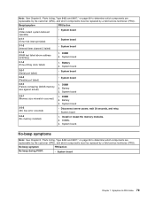
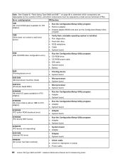
...3-2-1 (Serial port failed) v System board 3-2-2 (Parallel port failed) v System board 3-2-4 (Failure comparing CMOS memory size against actual) 1. Battery 3. Note: See Chapter 8, "Parts listing, Type 8482 and 8487," on page 99 to determine which components are replaceable by the customer (CRU), and which components must...) v Disconnect server power, wait 30 seconds, and retry. DIMMs. 3. No-beep symptoms Note: See Chapter 8, "Parts listing, Type 8482 and 8487," on page 99 to -FRU index 79 No-beep symptom FRU/action No beep during POST. Symptom-to determine which components are...
...3-2-1 (Serial port failed) v System board 3-2-2 (Parallel port failed) v System board 3-2-4 (Failure comparing CMOS memory size against actual) 1. Battery 3. Note: See Chapter 8, "Parts listing, Type 8482 and 8487," on page 99 to determine which components are replaceable by the customer (CRU), and which components must...) v Disconnect server power, wait 30 seconds, and retry. DIMMs. 3. No-beep symptoms Note: See Chapter 8, "Parts listing, Type 8482 and 8487," on page 99 to -FRU index 79 No-beep symptom FRU/action No beep during POST. Symptom-to determine which components are...
User Manual
Page 90
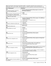
...8487," on password damaged) 1. Run the Configuration/Setup Utility program. 2. Failing device. 4. System board. 80 xSeries 206 Type 8482 and 8487: Hardware Maintenance Manual and Troubleshooting Guide Battery. 3. Battery. 3. System board. 163 (Real-time clock ....) 1. Microprocessor. 101, 102 (System and processor error) v System board 106 (System and processor error) v System board 114 (Adapter read-only memory error (check 55 AA)) 1. Battery. 3. Adapter. 151 (Real time clock error) 1. Battery 2. Battery. 3. System board. 162 (Device configuration...
...8487," on password damaged) 1. Run the Configuration/Setup Utility program. 2. Failing device. 4. System board. 80 xSeries 206 Type 8482 and 8487: Hardware Maintenance Manual and Troubleshooting Guide Battery. 3. Battery. 3. System board. 163 (Real-time clock ....) 1. Microprocessor. 101, 102 (System and processor error) v System board 106 (System and processor error) v System board 114 (Adapter read-only memory error (check 55 AA)) 1. Battery. 3. Adapter. 151 (Real time clock error) 1. Battery 2. Battery. 3. System board. 162 (Device configuration...
User Manual
Page 91
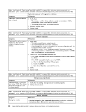
... 2. System board. 662 (Diskette drive configuration error) 1. Diskette drive. 3. Run the Configuration/Setup Utility program. 3. Note: See Chapter 8, "Parts listing, Type 8482 and 8487," on the parallel port. 2. DIMM (Memory test error.) If the server does not have the latest level of BIOS installed, 2. Run the Configuration/Setup Utility program, if the...
... 2. System board. 662 (Diskette drive configuration error) 1. Diskette drive. 3. Run the Configuration/Setup Utility program. 3. Note: See Chapter 8, "Parts listing, Type 8482 and 8487," on the parallel port. 2. DIMM (Memory test error.) If the server does not have the latest level of BIOS installed, 2. Run the Configuration/Setup Utility program, if the...
User Manual
Page 92
... Run the Configuration/Setup Utility program. 2. Battery. 8603 (Pointing-device error) 1. Adapter. 3. Adapter 2. Power cable. 82 xSeries 206 Type 8482 and 8487: Hardware Maintenance Manual and Troubleshooting Guide Run the Configuration/Setup Utility program. 2. System board. 00180500 (PCI option ROM ...Microprocessor machine check) 1. System board 00180200 (No more ROM space available for PCI adapter) 1. System board. 00180300 (No more memory above 1MB for interruption of power. 3. System board I9990650 (AC power has been restored) 1. Cable. 6. IDE cable. 5....
... Run the Configuration/Setup Utility program. 2. Battery. 8603 (Pointing-device error) 1. Adapter. 3. Adapter 2. Power cable. 82 xSeries 206 Type 8482 and 8487: Hardware Maintenance Manual and Troubleshooting Guide Run the Configuration/Setup Utility program. 2. System board. 00180500 (PCI option ROM ...Microprocessor machine check) 1. System board 00180200 (No more ROM space available for PCI adapter) 1. System board. 00180300 (No more memory above 1MB for interruption of power. 3. System board I9990650 (AC power has been restored) 1. Cable. 6. IDE cable. 5....

User Manual
Page 94
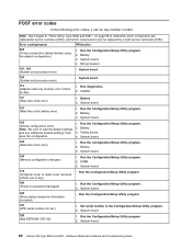
... by the customer (CRU), and which components must be replaced by a field service technician (FRU). System board. 201-XXX-0nn (Failed memory test.) 1. Verify microprocessor 1 is at latest level. 3. System board. 202-XXX-002 (Failed system cache test) 1. Cable. 3. ... correctly. 2. Verify microprocessor 2 is not configured properly. System board. 206-XXX-000 (Failed diskette drive test) 1. Rerun the test using another CD-ROM. 2. System board. 84 xSeries 206 Type 8482 and 8487: Hardware Maintenance Manual and Troubleshooting Guide Error code/symptom FRU/action...
... by the customer (CRU), and which components must be replaced by a field service technician (FRU). System board. 201-XXX-0nn (Failed memory test.) 1. Verify microprocessor 1 is at latest level. 3. System board. 202-XXX-002 (Failed system cache test) 1. Cable. 3. ... correctly. 2. Verify microprocessor 2 is not configured properly. System board. 206-XXX-000 (Failed diskette drive test) 1. Rerun the test using another CD-ROM. 2. System board. 84 xSeries 206 Type 8482 and 8487: Hardware Maintenance Manual and Troubleshooting Guide Error code/symptom FRU/action...
User Manual
Page 98
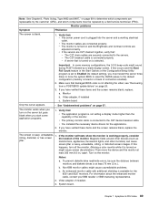
... log for adjusting and testing instructions. (Some IBM monitors have their own self-tests.) 88 xSeries 206 Type 8482 and 8487: Hardware Maintenance Manual and Troubleshooting Guide v The mouse device drivers are enabled. Note: See Chapter 8, "Parts listing, Type 8482 and 8487," on page 99 to determine which...mouse or pointing device does not work. 1. Verify that the startup microprocessor is less than the amount of memory. Note: See Chapter 8, "Parts listing, Type 8482 and 8487," on page 99 to determine which components are replaceable by the customer (CRU), and which ...
... log for adjusting and testing instructions. (Some IBM monitors have their own self-tests.) 88 xSeries 206 Type 8482 and 8487: Hardware Maintenance Manual and Troubleshooting Guide v The mouse device drivers are enabled. Note: See Chapter 8, "Parts listing, Type 8482 and 8487," on page 99 to determine which...mouse or pointing device does not work. 1. Verify that the startup microprocessor is less than the amount of memory. Note: See Chapter 8, "Parts listing, Type 8482 and 8487," on page 99 to determine which components are replaceable by the customer (CRU), and which ...
User Manual
Page 99
...transformers, appliances, fluorescent lights, and other devices (such as jitter. b. Non-IBM monitor cables might sound during POST followed by a field service technician (FRU). System board. Note: See Chapter 8, "Parts listing, Type 8482 and 8487," on page 99 to the C2T device breakout cable. v The ...restart the server three times to force the system BIOS to reset the CMOS values to Enabled (its default setting), you start some memory configurations, the 3-3-3 beep code might cause unpredictable problems. c. Magnetic fields around other monitors) can cause screen jitter or wavy, ...
...transformers, appliances, fluorescent lights, and other devices (such as jitter. b. Non-IBM monitor cables might sound during POST followed by a field service technician (FRU). System board. Note: See Chapter 8, "Parts listing, Type 8482 and 8487," on page 99 to the C2T device breakout cable. v The ...restart the server three times to force the system BIOS to reset the CMOS values to Enabled (its default setting), you start some memory configurations, the 3-3-3 beep code might cause unpredictable problems. c. Magnetic fields around other monitors) can cause screen jitter or wavy, ...
User Manual
Page 100
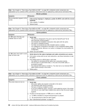
...outlet functions properly. If LEDs for microprocessors or VRMs are replaceable by the customer (CRU), and which components are on page 97. 90 xSeries 206 Type 8482 and 8487: Hardware Maintenance Manual and Troubleshooting Guide See "Undetermined problems" on , verify that used to the server. Note: See Chapter ... an option is designed for all of memory installed is installed correctly. Verify that : v The cables for the server (see the ServerProven® list at http://www.ibm.com/pc/compat/). v You updated the configuration information in each SCSI chain, or the end of the ...
...outlet functions properly. If LEDs for microprocessors or VRMs are replaceable by the customer (CRU), and which components are on page 97. 90 xSeries 206 Type 8482 and 8487: Hardware Maintenance Manual and Troubleshooting Guide See "Undetermined problems" on , verify that used to the server. Note: See Chapter ... an option is designed for all of memory installed is installed correctly. Verify that : v The cables for the server (see the ServerProven® list at http://www.ibm.com/pc/compat/). v You updated the configuration information in each SCSI chain, or the end of the ...


