Manual
Page 1
GA-X58-USB3 LGA1366 socket motherboard for Intel® Core™ i7 processor family User's Manual Rev. 1001 12ME-X58USB3-1001R
GA-X58-USB3 LGA1366 socket motherboard for Intel® Core™ i7 processor family User's Manual Rev. 1001 12ME-X58USB3-1001R
Manual
Page 2
Motherboard GA-X58-USB3 Aug. 2, 2010 Motherboard GA-X58-USB3 Aug. 2, 2010
Motherboard GA-X58-USB3 Aug. 2, 2010 Motherboard GA-X58-USB3 Aug. 2, 2010
Manual
Page 3
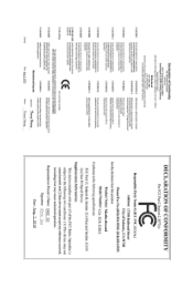
...product information, carefully read or download the information on/from the Support&Downloads\Motherboard\Technology Guide page on our website. Check your motherboard looks like this manual is protected by GIGABYTE without GIGABYTE's prior written permission. Copyright © 2010 GIGA-BYTE TECHNOLOGY CO., LTD.... product-related information, check on our website at: http://www.gigabyte.com Identifying Your Motherboard Revision The revision number on how to the specifications and features in this product, GIGABYTE provides the following types of documentations: For quick set-up of...
...product information, carefully read or download the information on/from the Support&Downloads\Motherboard\Technology Guide page on our website. Check your motherboard looks like this manual is protected by GIGABYTE without GIGABYTE's prior written permission. Copyright © 2010 GIGA-BYTE TECHNOLOGY CO., LTD.... product-related information, check on our website at: http://www.gigabyte.com Identifying Your Motherboard Revision The revision number on how to the specifications and features in this product, GIGABYTE provides the following types of documentations: For quick set-up of...
Manual
Page 4
Table of Contents Box Contents...6 Optional Items...6 GA-X58-USB3 Motherboard Layout 7 GA-X58-USB3 Motherboard Block Diagram 8 Chapter 1 Hardware Installation 9 1-1 Installation Precautions 9 1-2 Product Specifications 10 1-3 Installing the CPU and CPU Cooler 13 1-3-1 Installing the CPU 13 1-3-2 Installing the CPU Cooler ...
Table of Contents Box Contents...6 Optional Items...6 GA-X58-USB3 Motherboard Layout 7 GA-X58-USB3 Motherboard Block Diagram 8 Chapter 1 Hardware Installation 9 1-1 Installation Precautions 9 1-2 Product Specifications 10 1-3 Installing the CPU and CPU Cooler 13 1-3-1 Installing the CPU 13 1-3-2 Installing the CPU Cooler ...
Manual
Page 6
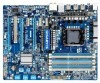
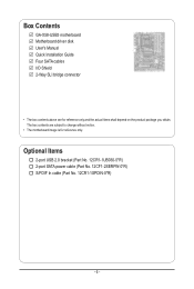
Optional Items 2-port USB 2.0 bracket (Part No. 12CR1-1UB030-5*R) 2-port SATA power cable (Part No. 12CF1-2SERPW-0*R) S/PDIF In cable (Part No. 12CR1-1SPDIN-0*R) - 6 - Box Contents GA-X58-USB3 motherboard Motherboard driver disk User's Manual Quick Installation Guide Four SATA cables I/O Shield 2-Way SLI bridge connector • The box contents above are subject to change without notice. • The motherboard image is for reference only and the actual items shall depend on the product package you obtain. The box contents are for reference only.
Optional Items 2-port USB 2.0 bracket (Part No. 12CR1-1UB030-5*R) 2-port SATA power cable (Part No. 12CF1-2SERPW-0*R) S/PDIF In cable (Part No. 12CR1-1SPDIN-0*R) - 6 - Box Contents GA-X58-USB3 motherboard Motherboard driver disk User's Manual Quick Installation Guide Four SATA cables I/O Shield 2-Way SLI bridge connector • The box contents above are subject to change without notice. • The motherboard image is for reference only and the actual items shall depend on the product package you obtain. The box contents are for reference only.
Manual
Page 7
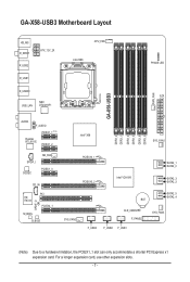
GA-X58-USB3 Motherboard Layout KB_MS R_SPDIF R_USB2 R_USB1 ATX_12V_2X R_USB30 USB_LAN NEC D720200F1 CPU_FAN LGA1366 PHASE LED ATX GA-X58-USB3 PWR_FAN AUDIO F_AUDIO PCIEX1_1 (Note) Realtek RTL8111E PCIEX1_2 Intel® X58 DDR3_2 DDR3_1 DDR3_4 DDR3_3 DDR3_6 DDR3_5 SYS_FAN1 SPDIF_I CODEC NB_FAN PCIEX1_3 CD_IN SPDIF_O iTE IT8720 PCI PCIEX4_1 M_BIOS B_BIOS PCIEX16_1 PCIEX16_2 Intel® ICH10R SATA2_1 ...
GA-X58-USB3 Motherboard Layout KB_MS R_SPDIF R_USB2 R_USB1 ATX_12V_2X R_USB30 USB_LAN NEC D720200F1 CPU_FAN LGA1366 PHASE LED ATX GA-X58-USB3 PWR_FAN AUDIO F_AUDIO PCIEX1_1 (Note) Realtek RTL8111E PCIEX1_2 Intel® X58 DDR3_2 DDR3_1 DDR3_4 DDR3_3 DDR3_6 DDR3_5 SYS_FAN1 SPDIF_I CODEC NB_FAN PCIEX1_3 CD_IN SPDIF_O iTE IT8720 PCI PCIEX4_1 M_BIOS B_BIOS PCIEX16_1 PCIEX16_2 Intel® ICH10R SATA2_1 ...
Manual
Page 8
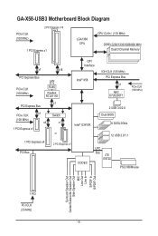
GA-X58-USB3 Motherboard Block Diagram PCIe CLK (100 MHz) 2 PCI Express x16 1 PCI Express x1 LGA1366 CPU CPU CLK+/- (133 MHz) DDR3 2200/1333/1066/800 MHz Dual/3 Channel Memory x1 x16 PCI Express Bus PCIe CLK (100 MHz) LAN RJ45 Realtek RTL8111E QPI Interface Intel® X58 IOH CLK (133 MHz) PCI Express Bus...
GA-X58-USB3 Motherboard Block Diagram PCIe CLK (100 MHz) 2 PCI Express x16 1 PCI Express x1 LGA1366 CPU CPU CLK+/- (133 MHz) DDR3 2200/1333/1066/800 MHz Dual/3 Channel Memory x1 x16 PCI Express Bus PCIe CLK (100 MHz) LAN RJ45 Realtek RTL8111E QPI Interface Intel® X58 IOH CLK (133 MHz) PCI Express Bus...

Manual
Page 9
...connectors. • It is best to wear an electrostatic discharge (ESD) wrist strap when handling electronic com- ponents such as a motherboard, CPU or memory. These stickers are required for warranty validation. • Always remove the AC power by your dealer. Hardware Installation... Chapter 1 Hardware Installation 1-1 Installation Precautions The motherboard contains numerous delicate electronic circuits and components which can lead to damage to system components as well as physical harm to the ...
...connectors. • It is best to wear an electrostatic discharge (ESD) wrist strap when handling electronic com- ponents such as a motherboard, CPU or memory. These stickers are required for warranty validation. • Always remove the AC power by your dealer. Hardware Installation... Chapter 1 Hardware Installation 1-1 Installation Precautions The motherboard contains numerous delicate electronic circuits and components which can lead to damage to system components as well as physical harm to the ...
Manual
Page 12
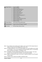
.... (Note 3) The PCIEX4_1 slot shares bandwidth with the PCIEX1_3 slot. if you are installing two PCI Express graphics cards, it in EasyTune may differ by motherboard model.
.... (Note 3) The PCIEX4_1 slot shares bandwidth with the PCIEX1_3 slot. if you are installing two PCI Express graphics cards, it in EasyTune may differ by motherboard model.

Manual
Page 13
.... 1-3 Installing the CPU and CPU Cooler Read the following guidelines before you begin to install the CPU: • Make sure that the motherboard supports the CPU. (Go to GIGABYTE's website for the peripherals. The CPU cannot be inserted if oriented incorrectly. (Or you wish to set beyond hardware specifications since it does... do so according to your hardware specifications including the CPU, graphics card, memory, hard drive, etc. 1-3-1 Installing the CPU A. Locate the alignment keys on the motherboard CPU socket and the notches on the CPU Notch Notch - 13 -
.... 1-3 Installing the CPU and CPU Cooler Read the following guidelines before you begin to install the CPU: • Make sure that the motherboard supports the CPU. (Go to GIGABYTE's website for the peripherals. The CPU cannot be inserted if oriented incorrectly. (Or you wish to set beyond hardware specifications since it does... do so according to your hardware specifications including the CPU, graphics card, memory, hard drive, etc. 1-3-1 Installing the CPU A. Locate the alignment keys on the motherboard CPU socket and the notches on the CPU Notch Notch - 13 -

Manual
Page 14
... into position. Step 5: Once the CPU is not installed.) Step 4: Hold the CPU with the socket alignment keys) and gently insert the CPU into the motherboard CPU socket. B. To protect the CPU socket, always replace the protective socket cover when the CPU is properly inserted, replace the load plate and push...
... into position. Step 5: Once the CPU is not installed.) Step 4: Hold the CPU with the socket alignment keys) and gently insert the CPU into the motherboard CPU socket. B. To protect the CPU socket, always replace the protective socket cover when the CPU is properly inserted, replace the load plate and push...
Manual
Page 15
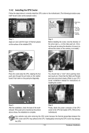
... and CPU may damage the CPU. - 15 - 1-3-2 Installing the CPU Cooler Follow the steps below to correctly install the CPU cooler on the motherboard. (The following procedure uses Intel® boxed cooler as the picture above shows, the installation is to install.) Step 3: Place the cooler atop ...the CPU, aligning the four push pins through the pin holes on the motherboard. Check that the Male and Female push pins are joined closely. (Refer to your CPU cooler installation manual for instructions on installing the cooler.)...
... and CPU may damage the CPU. - 15 - 1-3-2 Installing the CPU Cooler Follow the steps below to correctly install the CPU cooler on the motherboard. (The following procedure uses Intel® boxed cooler as the picture above shows, the installation is to install.) Step 3: Place the cooler atop ...the CPU, aligning the four push pins through the pin holes on the motherboard. Check that the Male and Female push pins are joined closely. (Refer to your CPU cooler installation manual for instructions on installing the cooler.)...
Manual
Page 16
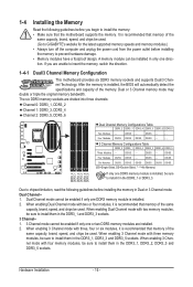
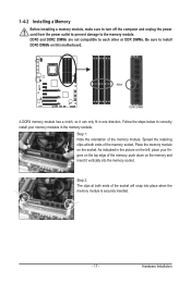
... begin to install the memory: • Make sure that memory of the same capacity, brand, speed, and chips be used. (Go to GIGABYTE's website for the latest supported memory speeds and memory modules.) • Always turn off the computer and unplug the power cord from the power.... When enabling 3 Channel mode with two memory modules, be sure to insert the memory, switch the direction. 1-4-1 Dual/3 Channel Memory Configuration This motherboard provides six DDR3 memory sockets and supports Dual/3 Channel Technology. DS/SS Six Modules DS/SS DS/SS DS/SS DS/SS DS/SS DS...
... begin to install the memory: • Make sure that memory of the same capacity, brand, speed, and chips be used. (Go to GIGABYTE's website for the latest supported memory speeds and memory modules.) • Always turn off the computer and unplug the power cord from the power.... When enabling 3 Channel mode with two memory modules, be sure to insert the memory, switch the direction. 1-4-1 Dual/3 Channel Memory Configuration This motherboard provides six DDR3 memory sockets and supports Dual/3 Channel Technology. DS/SS Six Modules DS/SS DS/SS DS/SS DS/SS DS/SS DS...
Manual
Page 17
... ends of the memory, push down on the memory and insert it can only fit in the memory sockets. Place the memory module on this motherboard. Notch DDR3 DIMM A DDR3 memory module has a notch, so it vertically into place when the memory module is securely inserted. - 17 - DDR3 and DDR2 DIMMs...
... ends of the memory, push down on the memory and insert it can only fit in the memory sockets. Place the memory module on this motherboard. Notch DDR3 DIMM A DDR3 memory module has a notch, so it vertically into place when the memory module is securely inserted. - 17 - DDR3 and DDR2 DIMMs...
Manual
Page 18
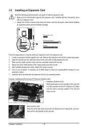
... turn off the computer and unplug the power cord from the power outlet before you begin to install an expansion card: • Make sure the motherboard supports the expansion card. Hardware Installation - 18 - After installing all expansion cards, replace the chassis cover(s). 6. 1-5 Installing an Expansion Card Read the following guidelines before...
... turn off the computer and unplug the power cord from the power outlet before you begin to install an expansion card: • Make sure the motherboard supports the expansion card. Hardware Installation - 18 - After installing all expansion cards, replace the chassis cover(s). 6. 1-5 Installing an Expansion Card Read the following guidelines before...
Manual
Page 19
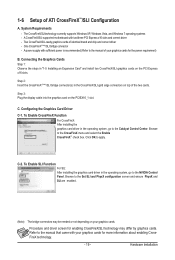
... Function For SLI: After installing the graphics card driver in the CrossFireX/SLI gold edge connectors on the PCI Express x16 slots. A CrossFireX/SLI-supported motherboard with sufficient power is recommended (Refer to the Catalyst Control Center. Connecting the Graphics Cards Step 1: Observe the steps in the operating system, go to...
... Function For SLI: After installing the graphics card driver in the CrossFireX/SLI gold edge connectors on the PCI Express x16 slots. A CrossFireX/SLI-supported motherboard with sufficient power is recommended (Refer to the Catalyst Control Center. Connecting the Graphics Cards Step 1: Observe the steps in the operating system, go to...
Manual
Page 20
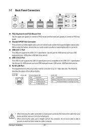
... port (green) to connect a PS/2 mouse and the lower port (purple) to an external audio system that your device and then remove it from the motherboard. • When removing the cable, pull it side to side to 1 Gbps data rate. Use this port for USB devices such as a USB keyboard/mouse...
... port (green) to connect a PS/2 mouse and the lower port (purple) to an external audio system that your device and then remove it from the motherboard. • When removing the cable, pull it side to side to 1 Gbps data rate. Use this port for USB devices such as a USB keyboard/mouse...
Manual
Page 22
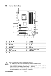
... 5 2 4 7 8 4 4 14 15 9 9) F_PANEL 10) F_AUDIO 11) CD_IN 12) SPDIF_I 13) SPDIF_O 14) F_USB1/F_USB2/F_USB3 15) CLR_CMOS Read the following guidelines before turning on the motherboard. Unplug the power cord from the power outlet to prevent damage to the devices. • After installing the device and before connecting external devices: •...
... 5 2 4 7 8 4 4 14 15 9 9) F_PANEL 10) F_AUDIO 11) CD_IN 12) SPDIF_I 13) SPDIF_O 14) F_USB1/F_USB2/F_USB3 15) CLR_CMOS Read the following guidelines before turning on the motherboard. Unplug the power cord from the power outlet to prevent damage to the devices. • After installing the device and before connecting external devices: •...
Manual
Page 23
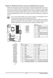
... system. 8 4 5 1 ATX_12V_2X ATX_12V_2X: Pin No. Before connecting the power connector, first make sure the power supply is turned off and all the components on the motherboard. 1/2) ATX_12V_2X/ATX (2x4 12V Power Connector and 2x12 Main Power Connector) With the use of a power supply providing a 2x4 12V power connector is recommended by...
... system. 8 4 5 1 ATX_12V_2X ATX_12V_2X: Pin No. Before connecting the power connector, first make sure the power supply is turned off and all the components on the motherboard. 1/2) ATX_12V_2X/ATX (2x4 12V Power Connector and 2x12 Main Power Connector) With the use of a power supply providing a 2x4 12V power connector is recommended by...
Manual
Page 24
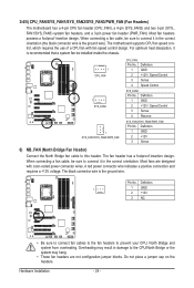
...result in damage to connect it in the correct orientation (the black connector wire is the ground wire. Hardware Installation - 24 - The motherboard supports CPU fan speed control, which requires the use of a CPU fan with color-coded power connector wires. Definition 1 GND 2 +... 3 Sense 4 Reserve SYS_FAN1/SYS_FAN3/PWR_FAN: Pin No. The fan header has a foolproof insertion design. 3/4/5) CPU_FAN/SYS_FAN1/SYS_FAN2/SYS_FAN3/PWR_FAN (Fan Headers) The motherboard has a 4-pin CPU fan header (CPU_FAN), a 4-pin (SYS_FAN2) and two 3-pin (SYS_ FAN1/SYS_FAN3) system fan headers, and a 3-pin power ...
...result in damage to connect it in the correct orientation (the black connector wire is the ground wire. Hardware Installation - 24 - The motherboard supports CPU fan speed control, which requires the use of a CPU fan with color-coded power connector wires. Definition 1 GND 2 +... 3 Sense 4 Reserve SYS_FAN1/SYS_FAN3/PWR_FAN: Pin No. The fan header has a foolproof insertion design. 3/4/5) CPU_FAN/SYS_FAN1/SYS_FAN2/SYS_FAN3/PWR_FAN (Fan Headers) The motherboard has a 4-pin CPU fan header (CPU_FAN), a 4-pin (SYS_FAN2) and two 3-pin (SYS_ FAN1/SYS_FAN3) system fan headers, and a 3-pin power ...


