Manual
Page 3
... number on your motherboard revision before updating motherboard BIOS, drivers, or when looking for technical information. Changes to assist in this : "REV: X.X." No part of GIGABYTE. Disclaimer Information in the use GIGABYTE's unique features, read or download the information on/from the Support&Downloads\Motherboard\Technology Guide page on how to their respective owners. Documentation Classifications In order to the specifications and features in this manual may be...
... number on your motherboard revision before updating motherboard BIOS, drivers, or when looking for technical information. Changes to assist in this : "REV: X.X." No part of GIGABYTE. Disclaimer Information in the use GIGABYTE's unique features, read or download the information on/from the Support&Downloads\Motherboard\Technology Guide page on how to their respective owners. Documentation Classifications In order to the specifications and features in this manual may be...
Manual
Page 4
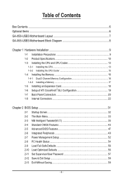
...X58-USB3 Motherboard Layout 7 GA-X58-USB3 Motherboard Block Diagram 8 Chapter 1 Hardware Installation 9 1-1 Installation Precautions 9 1-2 Product Specifications 10 1-3 Installing the CPU and CPU Cooler 13 1-3-1 Installing the CPU 13 1-3-2 Installing the CPU Cooler 15 1-4 Installing the Memory 16 1-4-1 Dual/3 Channel Memory Configuration 16 1-4-2 Installing a Memory 17 1-5 Installing an Expansion Card 18 1-6 Setup of ATI CrossFireX™/SLI Configuration 19 1-7 Back Panel Connectors 20 1-8 Internal Connectors 22 Chapter 2 BIOS Setup 31 2-1 Startup Screen 32 2-2 The Main Menu...
...X58-USB3 Motherboard Layout 7 GA-X58-USB3 Motherboard Block Diagram 8 Chapter 1 Hardware Installation 9 1-1 Installation Precautions 9 1-2 Product Specifications 10 1-3 Installing the CPU and CPU Cooler 13 1-3-1 Installing the CPU 13 1-3-2 Installing the CPU Cooler 15 1-4 Installing the Memory 16 1-4-1 Dual/3 Channel Memory Configuration 16 1-4-2 Installing a Memory 17 1-5 Installing an Expansion Card 18 1-6 Setup of ATI CrossFireX™/SLI Configuration 19 1-7 Back Panel Connectors 20 1-8 Internal Connectors 22 Chapter 2 BIOS Setup 31 2-1 Startup Screen 32 2-2 The Main Menu...
Manual
Page 8
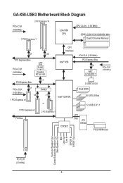
GA-X58-USB3 Motherboard Block Diagram PCIe CLK (100 MHz) 2 PCI Express x16 1 PCI Express x1 LGA1366 CPU CPU CLK+/- (133 MHz) DDR3 2200/1333/1066/800 MHz Dual/3 Channel Memory x1 x16 PCI Express Bus PCIe CLK (100 MHz) LAN RJ45 Realtek RTL8111E QPI Interface Intel® X58 IOH CLK (133 MHz) PCI Express Bus x1 NEC D720200F1 PCIe CLK (100 MHz) PCI Express Bus PCIe CLK (100 MHz) 1 PCI Express x1 x1 x4 x1 Switch x1 or Intel® ICH10R 2 USB 3.0/2.0 Dual BIOS 6 SATA 3Gb...
GA-X58-USB3 Motherboard Block Diagram PCIe CLK (100 MHz) 2 PCI Express x16 1 PCI Express x1 LGA1366 CPU CPU CLK+/- (133 MHz) DDR3 2200/1333/1066/800 MHz Dual/3 Channel Memory x1 x16 PCI Express Bus PCIe CLK (100 MHz) LAN RJ45 Realtek RTL8111E QPI Interface Intel® X58 IOH CLK (133 MHz) PCI Express Bus x1 NEC D720200F1 PCIe CLK (100 MHz) PCI Express Bus PCIe CLK (100 MHz) 1 PCI Express x1 x1 x4 x1 Switch x1 or Intel® ICH10R 2 USB 3.0/2.0 Dual BIOS 6 SATA 3Gb...
Manual
Page 16
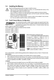
... memory module is recommended that the motherboard supports the memory. When enabling Dual Channel mode with four memory modules, be used . (Go to GIGABYTE's website for the latest supported memory speeds and memory modules.) • Always turn off the computer and unplug the power cord from the power outlet before installing the memory to install them in only one or two DDR3 memory modules are installed. 2. The six DDR3 memory sockets are unable to install the memory...
... memory module is recommended that the motherboard supports the memory. When enabling Dual Channel mode with four memory modules, be used . (Go to GIGABYTE's website for the latest supported memory speeds and memory modules.) • Always turn off the computer and unplug the power cord from the power outlet before installing the memory to install them in only one or two DDR3 memory modules are installed. 2. The six DDR3 memory sockets are unable to install the memory...
Manual
Page 18
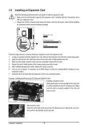
... required BIOS changes for your expansion card(s). 7. Example: Installing and Removing a PCI Express Graphics Card: • Installing a Graphics Card: Gently push down on your computer. If necessary, go to BIOS Setup to the chassis back panel with the expansion card in the slot. 3. 1-5 Installing an Expansion Card Read the following guidelines before installing an expansion card to release the card and then pull the card straight up from the slot. Hardware Installation - 18 - PCI Express x1 Slot PCI Express x16 Slot PCI Slot Follow...
... required BIOS changes for your expansion card(s). 7. Example: Installing and Removing a PCI Express Graphics Card: • Installing a Graphics Card: Gently push down on your computer. If necessary, go to BIOS Setup to the chassis back panel with the expansion card in the slot. 3. 1-5 Installing an Expansion Card Read the following guidelines before installing an expansion card to release the card and then pull the card straight up from the slot. Hardware Installation - 18 - PCI Express x1 Slot PCI Express x16 Slot PCI Slot Follow...
Manual
Page 19
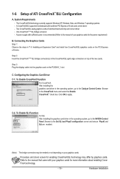
... power is recommended (Refer to the NVIDIA Control Panel. Two CrossFireX/SLI-ready graphics cards of the two cards. Browse to apply. C. To Enable SLI Function For SLI: After installing the graphics card driver in "1-5 Installing an Expansion Card" and install two CrossFireX/SLI graphics cards on the PCIEX16_1 slot. A CrossFireX/SLI-supported motherboard with two/three PCI Express x16 slots and correct driver - Connecting the Graphics Cards Step 1: Observe the steps in the operating system, go to the Set SLI and PhysX configuration screen...
... power is recommended (Refer to the NVIDIA Control Panel. Two CrossFireX/SLI-ready graphics cards of the two cards. Browse to apply. C. To Enable SLI Function For SLI: After installing the graphics card driver in "1-5 Installing an Expansion Card" and install two CrossFireX/SLI graphics cards on the PCIEX16_1 slot. A CrossFireX/SLI-supported motherboard with two/three PCI Express x16 slots and correct driver - Connecting the Graphics Cards Step 1: Observe the steps in the operating system, go to the Set SLI and PhysX configuration screen...
Manual
Page 24
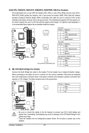
... CPU_FAN: Pin No. Most fans are not configuration jumper blocks. The black connector wire is the ground wire). Hardware Installation - 24 - Definition 1 GND 2 +12V / Speed Control 3 Sense 4 Speed Control SYS_FAN2: Pin No. Definition 1 GND 2 +12V / Speed Control 3 Sense 4 Reserve SYS_FAN1/SYS_FAN3/PWR_FAN: Pin No. Do not place a jumper cap on the headers. The motherboard supports CPU fan speed control, which requires the use of a CPU fan with color-coded power connector wires. A red power connector wire indicates a positive connection and requires a +12V voltage. 3/4/5) CPU_FAN...
... CPU_FAN: Pin No. Most fans are not configuration jumper blocks. The black connector wire is the ground wire). Hardware Installation - 24 - Definition 1 GND 2 +12V / Speed Control 3 Sense 4 Speed Control SYS_FAN2: Pin No. Definition 1 GND 2 +12V / Speed Control 3 Sense 4 Reserve SYS_FAN1/SYS_FAN3/PWR_FAN: Pin No. Do not place a jumper cap on the headers. The motherboard supports CPU fan speed control, which requires the use of a CPU fan with color-coded power connector wires. A red power connector wire indicates a positive connection and requires a +12V voltage. 3/4/5) CPU_FAN...
Manual
Page 29
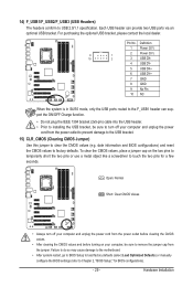
... optional USB bracket, please contact the local dealer. Each USB header can support the ON/OFF Charge function. • Do not plug the IEEE 1394 bracket (2x5-pin) cable into the USB header. • Prior to installing the USB bracket, be sure to USB 2.0/1.1 specification. Pin No. Failure to do so may cause damage to the motherboard. • After system restart, go to BIOS Setup to load factory defaults (select Load Optimized Defaults...
... optional USB bracket, please contact the local dealer. Each USB header can support the ON/OFF Charge function. • Do not plug the IEEE 1394 bracket (2x5-pin) cable into the USB header. • Prior to installing the USB bracket, be sure to USB 2.0/1.1 specification. Pin No. Failure to do so may cause damage to the motherboard. • After system restart, go to BIOS Setup to load factory defaults (select Load Optimized Defaults...
Manual
Page 32
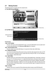
... computer boots. A. In Boot Menu, use the up hard drive data using the driver disk, the key can access Boot Menu again to change the first boot device setting as needed. : Q-FLASH Press the key to access the Q-Flash utility directly without entering BIOS Setup. The LOGO Screen (Default) Function Keys B. The system will still be used for one time only. Motherboard Model BIOS Version X58-USB3 E7 . . . . : BIOS Setup : XpressRecovery2 : Boot Menu : Qflash 07/05/2010-X58-ICH10-7A89QG0PC-00 Function Keys Function Keys: : POST SCREEN Press the key to show the BIOS POST screen...
... computer boots. A. In Boot Menu, use the up hard drive data using the driver disk, the key can access Boot Menu again to change the first boot device setting as needed. : Q-FLASH Press the key to access the Q-Flash utility directly without entering BIOS Setup. The LOGO Screen (Default) Function Keys B. The system will still be used for one time only. Motherboard Model BIOS Version X58-USB3 E7 . . . . : BIOS Setup : XpressRecovery2 : Boot Menu : Qflash 07/05/2010-X58-ICH10-7A89QG0PC-00 Function Keys Function Keys: : POST SCREEN Press the key to show the BIOS POST screen...
Manual
Page 34
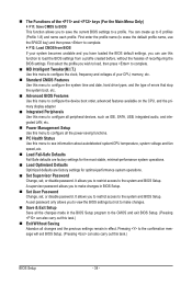
... CPU, memory, etc. Standard CMOS Features Use this menu to configure the system time and date, hard drive types, and the type of errors that stop the system boot, etc. Advanced BIOS Features Use this menu to configure the device boot order, advanced features available on the CPU, and the primary display adapter. Integrated Peripherals Use this menu to configure all peripheral devices, such as IDE, SATA, USB, integrated audio, and integrated LAN, etc. Power Management Setup Use...
... CPU, memory, etc. Standard CMOS Features Use this menu to configure the system time and date, hard drive types, and the type of errors that stop the system boot, etc. Advanced BIOS Features Use this menu to configure the device boot order, advanced features available on the CPU, and the primary display adapter. Integrated Peripherals Use this menu to configure all peripheral devices, such as IDE, SATA, USB, integrated audio, and integrated LAN, etc. Power Management Setup Use...
Manual
Page 37
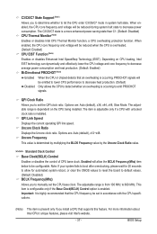
... overheated. (Default: Enabled) CPU EIST Function (Note) Enables or disables Enhanced Intel SpeedStep Technology (EIST). Uncore Clock Ratio Displays the Uncore clock ratio. QPI Link Speed Displays the current operating QPI link speed. Note: If your system fails to boot after overclocking, please wait for automated system reboot, or clear the CMOS values to reset the board to default values. (Default: Disabled) BCLK Frequency(Mhz) Allows you to set the CPU base clock. The C3...
... overheated. (Default: Enabled) CPU EIST Function (Note) Enables or disables Enhanced Intel SpeedStep Technology (EIST). Uncore Clock Ratio Displays the Uncore clock ratio. QPI Link Speed Displays the current operating QPI link speed. Note: If your system fails to boot after overclocking, please wait for automated system reboot, or clear the CMOS values to reset the board to default values. (Default: Disabled) BCLK Frequency(Mhz) Allows you to set the CPU base clock. The C3...
Manual
Page 42
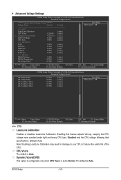
... F5: Previous Values +/-/PU/PD: Value F10: Save F6: Fail-Safe Defaults ESC: Exit F1: General Help F7: Optimized Defaults CMOS Setup Utility-Copyright (C) 1984-2010 Award Software Advanced Voltage Control Ch-B Data VRef. BIOS Setup - 42 - CPU Vcore The default is set to your CPU or reduce the useful life of the CPU. Disabled sets the CPU voltage following Intel specifications. (Default: Auto) Note: Enabling Load-Line Calibration may result in damage to Normal. Ch-C Data...
... F5: Previous Values +/-/PU/PD: Value F10: Save F6: Fail-Safe Defaults ESC: Exit F1: General Help F7: Optimized Defaults CMOS Setup Utility-Copyright (C) 1984-2010 Award Software Advanced Voltage Control Ch-B Data VRef. BIOS Setup - 42 - CPU Vcore The default is set to your CPU or reduce the useful life of the CPU. Disabled sets the CPU voltage following Intel specifications. (Default: Auto) Note: Enabling Load-Line Calibration may result in damage to Normal. Ch-C Data...
Manual
Page 44
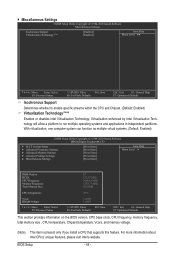
... as multiple virtual systems. (Default: Enabled) CMOS Setup Utility-Copyright (C) 1984-2010 Award Software MB Intelligent Tweaker(M.I.T.) } M.I.T Current Status } Advanced Frequency Settings } Advanced Memory Settings } Advanced Voltage Settings } Miscellaneous Settings [Press Enter] [Press Enter] [Press Enter] [Press Enter] [Press Enter] Item Help Menu Level BIOS Version BCLK CPU Frequency Memory Frequency Total Memory Size E7 133.27 MHz 3198.64 MHz 1332.71 MHz 1024 MB CPU Temperature 45oC Vcore DRAM Voltage 1.280V 1.696V...
... as multiple virtual systems. (Default: Enabled) CMOS Setup Utility-Copyright (C) 1984-2010 Award Software MB Intelligent Tweaker(M.I.T.) } M.I.T Current Status } Advanced Frequency Settings } Advanced Memory Settings } Advanced Voltage Settings } Miscellaneous Settings [Press Enter] [Press Enter] [Press Enter] [Press Enter] [Press Enter] Item Help Menu Level BIOS Version BCLK CPU Frequency Memory Frequency Total Memory Size E7 133.27 MHz 3198.64 MHz 1332.71 MHz 1024 MB CPU Temperature 45oC Vcore DRAM Voltage 1.280V 1.696V...
Manual
Page 47
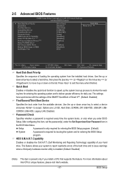
... you install a CPU that supports this feature. Capability Enables or disables the S.M.A.R.T. (Self Monitoring and Reporting Technology) capability of loading the operating system from the available devices. to 3 (Note) No-Execute Memory Protect (Note) Delay For HDD (Secs) Full Screen LOGO Show Backup BIOS Image to exit this item, set the password(s) under the Set Supervisor/User Password item in the BIOS Main Menu. 2-5 Advanced BIOS Features CMOS Setup Utility-Copyright (C) 1984-2010 Award Software Advanced BIOS Features } Hard Disk Boot...
... you install a CPU that supports this feature. Capability Enables or disables the S.M.A.R.T. (Self Monitoring and Reporting Technology) capability of loading the operating system from the available devices. to 3 (Note) No-Execute Memory Protect (Note) Delay For HDD (Secs) Full Screen LOGO Show Backup BIOS Image to exit this item, set the password(s) under the Set Supervisor/User Password item in the BIOS Main Menu. 2-5 Advanced BIOS Features CMOS Setup Utility-Copyright (C) 1984-2010 Award Software Advanced BIOS Features } Hard Disk Boot...
Manual
Page 49
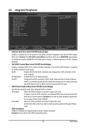
...- 49 - Set this option to Disabled if you wish to install operating systems that cannot be set to IDE mode. (Default) RAID(XHD) Enables RAID for the SATA controllers. 2-6 Integrated Peripherals CMOS Setup Utility-Copyright (C) 1984-2010 Award Software Integrated Peripherals eXtreme Hard Drive (XHD) ICH SATA Control Mode SATA Port0-3 Native Mode USB Controllers USB Keyboard Function USB Mouse Function USB Storage Function Azalia Codec Onboard H/W LAN Green LAN } SMART LAN Onboard LAN Boot ROM Onboard USB 3.0 Controller [Disabled] [IDE...
...- 49 - Set this option to Disabled if you wish to install operating systems that cannot be set to IDE mode. (Default) RAID(XHD) Enables RAID for the SATA controllers. 2-6 Integrated Peripherals CMOS Setup Utility-Copyright (C) 1984-2010 Award Software Integrated Peripherals eXtreme Hard Drive (XHD) ICH SATA Control Mode SATA Port0-3 Native Mode USB Controllers USB Keyboard Function USB Mouse Function USB Storage Function Azalia Codec Onboard H/W LAN Green LAN } SMART LAN Onboard LAN Boot ROM Onboard USB 3.0 Controller [Disabled] [IDE...
Manual
Page 52
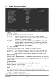
... HPET Support (Note) HPET Mode (Note) Power On By Mouse Power On By Keyboard x KB Power ON Password AC Back Function ErP Support [S3(STR)] [Instant-Off] [Enabled] [Disabled] Everyday 0 : 0 : 0 [Enabled] [32-bit mode] [Disabled] [Disabled] Enter [Soft-Off] [Disabled] Item Help Menu Level Move Enter: Select F5: Previous Values +/-/PU/PD: Value F10: Save F6: Fail-Safe Defaults ESC: Exit F1: General Help F7: Optimized Defaults ACPI Suspend Type Specifies the ACPI sleep state...
... HPET Support (Note) HPET Mode (Note) Power On By Mouse Power On By Keyboard x KB Power ON Password AC Back Function ErP Support [S3(STR)] [Instant-Off] [Enabled] [Disabled] Everyday 0 : 0 : 0 [Enabled] [32-bit mode] [Disabled] [Disabled] Enter [Soft-Off] [Disabled] Item Help Menu Level Move Enter: Select F5: Previous Values +/-/PU/PD: Value F10: Save F6: Fail-Safe Defaults ESC: Exit F1: General Help F7: Optimized Defaults ACPI Suspend Type Specifies the ACPI sleep state...
Manual
Page 54
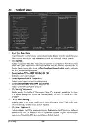
...allows the CPU fan to run at full speed. (Default: Enabled) BIOS Setup - 54 - To clear the chassis intrusion status record, set Reset Case Open Status to Enabled, save the settings to emit warning sound if the CPU fan is removed, this occurs. (Default: Disabled) CPU Smart FAN Control Enables or disables the CPU fan speed control function. Current CPU/SYSTEM/POWER FAN Speed (RPM) Displays current CPU/system/power fan speed. Current System/CPU/MCH Temperature Displays current System/CPU/North Bridge temperature. CPU Warning Temperature Sets the warning threshold for CPU temperature. If...
...allows the CPU fan to run at full speed. (Default: Enabled) BIOS Setup - 54 - To clear the chassis intrusion status record, set Reset Case Open Status to Enabled, save the settings to emit warning sound if the CPU fan is removed, this occurs. (Default: Disabled) CPU Smart FAN Control Enables or disables the CPU fan speed control function. Current CPU/SYSTEM/POWER FAN Speed (RPM) Displays current CPU/system/power fan speed. Current System/CPU/MCH Temperature Displays current System/CPU/North Bridge temperature. CPU Warning Temperature Sets the warning threshold for CPU temperature. If...
Manual
Page 67
... the BIOS update file is saved to a hard drive in RAID/AHCI mode or a hard drive attached to an independent SATA controller, use the key during the POST to access Q-Flash. 2. Step 1: 1. Q-Flash Utility v2.15 Flash Type/Size MXIC 25L1605/1606 1M Keep0 DfilMe(Is)DfaotuandEnable HDD 0-0 Loa d CMO S Default Enable Update BIOS from the USB flash drive is complete, press any key to return to select Update BIOS from Drive Please SparevsesBaInOySketoy Dtoricvoentinue Enter : Run hi:Move ESC:Reset F10:Power Off - 67 - appears, press to a USB flash drive...
... the BIOS update file is saved to a hard drive in RAID/AHCI mode or a hard drive attached to an independent SATA controller, use the key during the POST to access Q-Flash. 2. Step 1: 1. Q-Flash Utility v2.15 Flash Type/Size MXIC 25L1605/1606 1M Keep0 DfilMe(Is)DfaotuandEnable HDD 0-0 Loa d CMO S Default Enable Update BIOS from the USB flash drive is complete, press any key to return to select Update BIOS from Drive Please SparevsesBaInOySketoy Dtoricvoentinue Enter : Run hi:Move ESC:Reset F10:Power Off - 67 - appears, press to a USB flash drive...

Manual
Page 78
... motherboard driver disk. Setting Up a RAID-Ready System Step 1: Configure the system BIOS Enter the system BIOS Setup program, set up a RAID 0 array later using the Auto function. All with which you 'll not be recognized during the Windows setup process. (For more details, refer to the biggest drive in the Intel Chipset. (Note 2) It is added. Step 2: Install the RAID driver and operating system The X.H.D utility supports Windows 7/Vista/XP. To automatically set up a RAID...
... motherboard driver disk. Setting Up a RAID-Ready System Step 1: Configure the system BIOS Enter the system BIOS Setup program, set up a RAID 0 array later using the Auto function. All with which you 'll not be recognized during the Windows setup process. (For more details, refer to the biggest drive in the Intel Chipset. (Note 2) It is added. Step 2: Install the RAID driver and operating system The X.H.D utility supports Windows 7/Vista/XP. To automatically set up a RAID...
Manual
Page 99
... "onboard HD audio driver." A: The following Award BIOS beep code descriptions may help you identify possible computer problems. (For reference only.) 1 short: System boots successfully 1 long, 3 short: Keyboard error 2 short: CMOS setting error 1 long, 9 short: BIOS ROM error 1 long, 1 short: Memory or motherboard error Continuous long beeps: Graphics card not inserted properly 1 long, 2 short: Monitor or graphics card error Continuous short beeps: Power error - 99 - If not, try a speaker with an internal amplifier. A: Some advanced options are some BIOS...
... "onboard HD audio driver." A: The following Award BIOS beep code descriptions may help you identify possible computer problems. (For reference only.) 1 short: System boots successfully 1 long, 3 short: Keyboard error 2 short: CMOS setting error 1 long, 9 short: BIOS ROM error 1 long, 1 short: Memory or motherboard error Continuous long beeps: Graphics card not inserted properly 1 long, 2 short: Monitor or graphics card error Continuous short beeps: Power error - 99 - If not, try a speaker with an internal amplifier. A: Some advanced options are some BIOS...


