Manual
Page 7
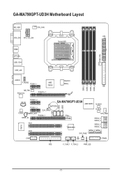
GA-MA790GPT-UD3H Motherboard Layout KB_USB CPU_FAN ATX VGA_DVI ATX_12V_2X4 Socket AM3 HDMI OPTICAL USB_1394 USB_LAN PWR_FAN F_USB1 F_USB2 F_USB3 DDR3_1 DDR3_2 DDR3_3 DDR3_4 AUDIO SidePort F_AUDIO PCIEX1_1 AMD 790GX Meory IDE NB_FAN RTL8111C PCIEX16_1 CD_IN PCIEX1_2 PCIEX1_3 GA-MA790GPT-UD3H AMD SB750 BATTERY CLR_CMOS M_BIOS B_BIOS CODEC SPDIF_OUT PCIEX8_1 SPDIF_IN PCI1 TSB43AB23 SYS_FAN1 SATA2_4 SATA2_5 SATA2_2 SATA2_3 IT8718 PCI2 SATA2_0 SATA2_1 SYS_FAN2 COM CI F_PANEL FDD F_1394_1 F_1394_2 PWR_LED - 7 -
GA-MA790GPT-UD3H Motherboard Layout KB_USB CPU_FAN ATX VGA_DVI ATX_12V_2X4 Socket AM3 HDMI OPTICAL USB_1394 USB_LAN PWR_FAN F_USB1 F_USB2 F_USB3 DDR3_1 DDR3_2 DDR3_3 DDR3_4 AUDIO SidePort F_AUDIO PCIEX1_1 AMD 790GX Meory IDE NB_FAN RTL8111C PCIEX16_1 CD_IN PCIEX1_2 PCIEX1_3 GA-MA790GPT-UD3H AMD SB750 BATTERY CLR_CMOS M_BIOS B_BIOS CODEC SPDIF_OUT PCIEX8_1 SPDIF_IN PCI1 TSB43AB23 SYS_FAN1 SATA2_4 SATA2_5 SATA2_2 SATA2_3 IT8718 PCI2 SATA2_0 SATA2_1 SYS_FAN2 COM CI F_PANEL FDD F_1394_1 F_1394_2 PWR_LED - 7 -

Manual
Page 12
... Saver Support for Time Repair Support for Q-Share Norton Internet Security (OEM version) Operating System w Support for Microsoft® Windows® Vista/XP Form Factor w ATX Form Factor; 30.5cm x 24.4cm (Note 1) Due to install it in EasyTune may differ by adapter. (Note 3) Simultaneous output for DVI-D and HDMI is..., be sure to Windows Vista/XP 32-bit operating system limitation, when more than 4 GB. (Note 2) The DVI-D port does not support D-Sub connection by motherboard model.
... Saver Support for Time Repair Support for Q-Share Norton Internet Security (OEM version) Operating System w Support for Microsoft® Windows® Vista/XP Form Factor w ATX Form Factor; 30.5cm x 24.4cm (Note 1) Due to install it in EasyTune may differ by adapter. (Note 3) Simultaneous output for DVI-D and HDMI is..., be sure to Windows Vista/XP 32-bit operating system limitation, when more than 4 GB. (Note 2) The DVI-D port does not support D-Sub connection by motherboard model.
Manual
Page 24
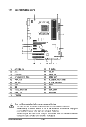
... prevent damage to turn off the devices and your computer. Hardware Installation - 24 - 1-9 Internal Connectors 13 5 2 8 12 6 21 13 20 4 14 15 16 9 18 1) ATX_12V_2X4 2) ATX 3) CPU_FAN 4) SYS_FAN1/SYS_FAN2 5) PWR_FAN 6) NB_FAN 7) FDD 8) IDE 9) SATA2_0/1/2/3/4/5 10) PWR_LED 11) F_PANEL 7 17 19 4 10 11 12) F_AUDIO 13) CD_IN 14) SPDIF_IN 15) SPDIF_OUT 16... connectors you wish to connect. • Before installing the devices, be sure to the devices. • After installing the device and before turning on the motherboard.
... prevent damage to turn off the devices and your computer. Hardware Installation - 24 - 1-9 Internal Connectors 13 5 2 8 12 6 21 13 20 4 14 15 16 9 18 1) ATX_12V_2X4 2) ATX 3) CPU_FAN 4) SYS_FAN1/SYS_FAN2 5) PWR_FAN 6) NB_FAN 7) FDD 8) IDE 9) SATA2_0/1/2/3/4/5 10) PWR_LED 11) F_PANEL 7 17 19 4 10 11 12) F_AUDIO 13) CD_IN 14) SPDIF_IN 15) SPDIF_OUT 16... connectors you wish to connect. • Before installing the devices, be sure to the devices. • After installing the device and before turning on the motherboard.
Manual
Page 25
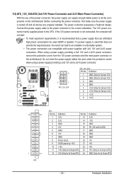
Before connecting the power connector, first make sure the power supply is turned off and all the components on the motherboard. If a power supply is recommended that a power supply that can withstand high power consumption be used that does not provide the required power, the result ...) 2 GND (Only for 2x4-pin 12V) 3 GND 4 GND 5 +12V (Only for 2x4-pin 12V) 6 +12V (Only for 2x4-pin 12V) 7 +12V 8 +12V 12 24 1 13 ATX ATX: Pin No. 1 2 3 4 5 6 7 8 9 10 11 12 Definition Pin No. 3.3V 13 3.3V 14 GND 15 +5V 16 GND 17 +5V 18 GND 19 Power Good 20...
Before connecting the power connector, first make sure the power supply is turned off and all the components on the motherboard. If a power supply is recommended that a power supply that can withstand high power consumption be used that does not provide the required power, the result ...) 2 GND (Only for 2x4-pin 12V) 3 GND 4 GND 5 +12V (Only for 2x4-pin 12V) 6 +12V (Only for 2x4-pin 12V) 7 +12V 8 +12V 12 24 1 13 ATX ATX: Pin No. 1 2 3 4 5 6 7 8 9 10 11 12 Definition Pin No. 3.3V 13 3.3V 14 GND 15 +5V 16 GND 17 +5V 18 GND 19 Power Good 20...
Manual
Page 97
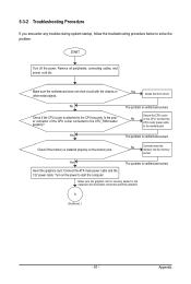
... properly? Appendix Remove all peripherals, connecting cables, and power cord etc. Insert the graphics card. A (Continued...) - 97 - Make sure the motherboard does not short-circuit with the chassis or other metal objects. Yes The problem is verified and solved. Yes The problem is verified and solved.... Connect the ATX main power cable and the 12V power cable. Make sure the graphics card is verified and solved. Yes Isolate the short circuit. ...
... properly? Appendix Remove all peripherals, connecting cables, and power cord etc. Insert the graphics card. A (Continued...) - 97 - Make sure the motherboard does not short-circuit with the chassis or other metal objects. Yes The problem is verified and solved. Yes The problem is verified and solved.... Connect the ATX main power cable and the 12V power cable. Make sure the graphics card is verified and solved. Yes Isolate the short circuit. ...


