Manual
Page 3
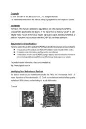
...by copyright laws and is 1.0. No part of this : "REV: X.X." For detailed product information, carefully read the Quick Installation Guide included with the product. The trademarks mentioned in this manual are legally registered to the specifications and features in this manual... BIOS, drivers, or when looking for technical information. For product-related information, check on our website at: http://www.gigabyte.com.tw Identifying Your Motherboard Revision The revision number on our website. Example: Changes to their respective owners. Documentation Classifications ...
...by copyright laws and is 1.0. No part of this : "REV: X.X." For detailed product information, carefully read the Quick Installation Guide included with the product. The trademarks mentioned in this manual are legally registered to the specifications and features in this manual... BIOS, drivers, or when looking for technical information. For product-related information, check on our website at: http://www.gigabyte.com.tw Identifying Your Motherboard Revision The revision number on our website. Example: Changes to their respective owners. Documentation Classifications ...
Manual
Page 4
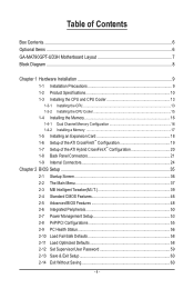
Table of Contents Box Contents...6 Optional Items...6 GA-MA790GPT-UD3H Motherboard Layout 7 Block Diagram...8 Chapter 1 Hardware Installation 9 1-1 Installation Precautions 9 1-2 Product Specifications 10 1-3 Installing the CPU and CPU Cooler 13 1-3-1 Installing the CPU 13 1-3-2 Installing the CPU Cooler 15 1-4 Installing the Memory 16 1-4-1 Dual Channel Memory Configuration 16 1-4-2 Installing a Memory 17 1-5 Installing an Expansion Card 18 1-6 Setup of the ATI CrossFireX™ Configuration...
Table of Contents Box Contents...6 Optional Items...6 GA-MA790GPT-UD3H Motherboard Layout 7 Block Diagram...8 Chapter 1 Hardware Installation 9 1-1 Installation Precautions 9 1-2 Product Specifications 10 1-3 Installing the CPU and CPU Cooler 13 1-3-1 Installing the CPU 13 1-3-2 Installing the CPU Cooler 15 1-4 Installing the Memory 16 1-4-1 Dual Channel Memory Configuration 16 1-4-2 Installing a Memory 17 1-5 Installing an Expansion Card 18 1-6 Setup of the ATI CrossFireX™ Configuration...
Manual
Page 5
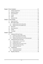
Chapter 3 Drivers Installation 61 3-1 Installing Chipset Drivers 61 3-2 Application Software 62 3-3 Technical Manuals 62 3-4 Contact...63 3-5 System...63 3-6 Download Center 64 Chapter 4 Unique Features 65 4-1 Xpress ...Repair...76 Chapter 5 Appendix...77 5-1 Configuring SATA Hard Drive(s 77 5-1-1 Configuring the Onboard SATA Controller 77 5-1-2 Making a SATA RAID/AHCI Driver Diskette 83 5-1-3 Installing the SATA RAID/AHCI Driver and Operating System 84 5-2 Configuring Audio Input and Output 88 5-2-1 Configuring 2/4/5.1/7.1-Channel Audio 88 5-2-2 Configuring S/PDIF In/Out 90 5-2-3...
Chapter 3 Drivers Installation 61 3-1 Installing Chipset Drivers 61 3-2 Application Software 62 3-3 Technical Manuals 62 3-4 Contact...63 3-5 System...63 3-6 Download Center 64 Chapter 4 Unique Features 65 4-1 Xpress ...Repair...76 Chapter 5 Appendix...77 5-1 Configuring SATA Hard Drive(s 77 5-1-1 Configuring the Onboard SATA Controller 77 5-1-2 Making a SATA RAID/AHCI Driver Diskette 83 5-1-3 Installing the SATA RAID/AHCI Driver and Operating System 84 5-2 Configuring Audio Input and Output 88 5-2-1 Configuring 2/4/5.1/7.1-Channel Audio 88 5-2-2 Configuring S/PDIF In/Out 90 5-2-3...
Manual
Page 6
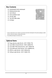
... cable (Part No. 12CR1-1SPDIN-0*R) COM port cable (Part No. 12CF1-1CM001-3*R) - 6 - The box contents are for reference only. Box Contents GA-MA790GPT-UD3H motherboard Motherboard driver disk User's Manual Quick Installation Guide One IDE cable Two SATA 3Gb/s cables I/O Shield • The box contents above are subject to change without notice. • The...
... cable (Part No. 12CR1-1SPDIN-0*R) COM port cable (Part No. 12CF1-1CM001-3*R) - 6 - The box contents are for reference only. Box Contents GA-MA790GPT-UD3H motherboard Motherboard driver disk User's Manual Quick Installation Guide One IDE cable Two SATA 3Gb/s cables I/O Shield • The box contents above are subject to change without notice. • The...

Manual
Page 8
The PCIEX8_1 slot shares bandwidth with a PCI Express graphics card, the PCIEX16_1 slot will operate at up to install it in the PCIEX16_1 slot. When PCIEX8_1 is not supported. - 8 - Simultaneous output for DVI-D and HDMI is populated with the PCIEX16_1 slot. Block Diagram 1 PCI ... In S/PDIF In S/PDIF Out 2 PCI PCI CLK (33 MHz) (Note 1) (Note 2) For optimum performance, if only one PCI Express graphics card is to be installed, be sure to x8 mode.
The PCIEX8_1 slot shares bandwidth with a PCI Express graphics card, the PCIEX16_1 slot will operate at up to install it in the PCIEX16_1 slot. When PCIEX8_1 is not supported. - 8 - Simultaneous output for DVI-D and HDMI is populated with the PCIEX16_1 slot. Block Diagram 1 PCI ... In S/PDIF In S/PDIF Out 2 PCI PCI CLK (33 MHz) (Note 1) (Note 2) For optimum performance, if only one PCI Express graphics card is to be installed, be sure to x8 mode.
Manual
Page 9
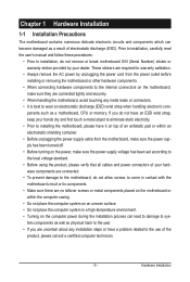
...the computer system in a high-temperature environment. • Turning on top of electrostatic discharge (ESD). Hardware Installation Chapter 1 Hardware Installation 1-1 Installation Precautions The motherboard contains numerous delicate electronic circuits and components which can lead to damage to system components as ...or within an electrostatic shielding container. • Before unplugging the power supply cable from the power outlet before installing or removing the motherboard or other hardware components. • When connecting hardware components to the internal connectors on ...
...the computer system in a high-temperature environment. • Turning on top of electrostatic discharge (ESD). Hardware Installation Chapter 1 Hardware Installation 1-1 Installation Precautions The motherboard contains numerous delicate electronic circuits and components which can lead to damage to system components as ...or within an electrostatic shielding container. • Before unplugging the power supply cable from the power outlet before installing or removing the motherboard or other hardware components. • When connecting hardware components to the internal connectors on ...
Manual
Page 10
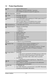
... USB IEEE 1394 Support for AM3 processors: AMD Phenom™ II processor/ AMD Athlon™ II processor/ (Go to GIGABYTE's website for the latest CPU support list.) 5200 MT/s North Bridge: AMD 790GX South Bridge: AMD SB750 4 x 1.5V... to 16 GB of system memory (Note 1) Dual channel memory architecture Support for DDR3 1666(O.C.)/1333/1066 MHz memory modules (Go to GIGABYTE's website for CD In 1 x RTL8111C chip (10/100/1000 Mbit) 1 x PCI Express x16 slot, running at x16 (PCIEX16_1...panel, 2 via the USB brackets connected to the internal IEEE 1394a headers) Hardware Installation - 10 -
... USB IEEE 1394 Support for AM3 processors: AMD Phenom™ II processor/ AMD Athlon™ II processor/ (Go to GIGABYTE's website for the latest CPU support list.) 5200 MT/s North Bridge: AMD 790GX South Bridge: AMD SB750 4 x 1.5V... to 16 GB of system memory (Note 1) Dual channel memory architecture Support for DDR3 1666(O.C.)/1333/1066 MHz memory modules (Go to GIGABYTE's website for CD In 1 x RTL8111C chip (10/100/1000 Mbit) 1 x PCI Express x16 slot, running at x16 (PCIEX16_1...panel, 2 via the USB brackets connected to the internal IEEE 1394a headers) Hardware Installation - 10 -
Manual
Page 11
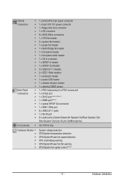
... temperature detection CPU/System/Power fan speed detection CPU overheating warning CPU/System/Power fan fail warning CPU/System fan speed control (Note 5) - 11 - Hardware Installation
... temperature detection CPU/System/Power fan speed detection CPU overheating warning CPU/System/Power fan fail warning CPU/System fan speed control (Note 5) - 11 - Hardware Installation

Manual
Page 12
...DMI 2.0, SM BIOS 2.4, ACPI 1.0b Support for @BIOS Support for Q-Flash Support for Xpress BIOS Rescue Support for Download Center Support for Xpress Install Support for Xpress Recovery2 Support for EasyTune (Note 6) Support for Easy Energy Saver Support for Time Repair Support for Q-Share Norton Internet Security (OEM...is supported will operate at up to x8 mode. (Note 5) Whether the CPU/system fan speed control function is to be installed, be sure to install it in EasyTune may differ by motherboard model. The PCIEX8_1 slot shares bandwidth with a PCI Express graphics card, the PCIEX16_1 slot...
...DMI 2.0, SM BIOS 2.4, ACPI 1.0b Support for @BIOS Support for Q-Flash Support for Xpress BIOS Rescue Support for Download Center Support for Xpress Install Support for Xpress Recovery2 Support for EasyTune (Note 6) Support for Easy Energy Saver Support for Time Repair Support for Q-Share Norton Internet Security (OEM...is supported will operate at up to x8 mode. (Note 5) Whether the CPU/system fan speed control function is to be installed, be sure to install it in EasyTune may differ by motherboard model. The PCIEX8_1 slot shares bandwidth with a PCI Express graphics card, the PCIEX16_1 slot...
Manual
Page 13
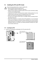
... keys on the CPU socket.) • Apply an even and thin layer of thermal grease on the computer if the CPU cooler is not installed, otherwise overheating and dam- It is not recommended that the motherboard supports the CPU. (Go to your hardware specifications including the CPU, graphics ...that the system bus frequency be inserted if oriented incorrectly. (Or you wish to set beyond the standard specifications, please do so according to GIGABYTE's website for the peripherals. Locate the pin one of the CPU. The CPU cannot be set the frequency beyond hardware specifications since it ...
... keys on the CPU socket.) • Apply an even and thin layer of thermal grease on the computer if the CPU cooler is not installed, otherwise overheating and dam- It is not recommended that the motherboard supports the CPU. (Go to your hardware specifications including the CPU, graphics ...that the system bus frequency be inserted if oriented incorrectly. (Or you wish to set beyond the standard specifications, please do so according to GIGABYTE's website for the peripherals. Locate the pin one of the CPU. The CPU cannot be set the frequency beyond hardware specifications since it ...
Manual
Page 14
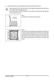
... the CPU into the fully locked position. Adjust the CPU orientation if this occurs. Follow the steps below to correctly install the CPU into the motherboard CPU socket. • Before installing the CPU, make sure to turn off the computer and unplug the power cord from the power outlet to prevent damage...
... the CPU into the fully locked position. Adjust the CPU orientation if this occurs. Follow the steps below to correctly install the CPU into the motherboard CPU socket. • Before installing the CPU, make sure to turn off the computer and unplug the power cord from the power outlet to prevent damage...
Manual
Page 15
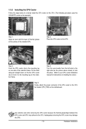
... hook it to the mounting lug on one side of the retention frame. 1-3-2 Installing the CPU Cooler Follow the steps below to correctly install the CPU cooler on the CPU. (The following procedure uses the GIGABYTE cooler as the picture above shows) to lock into place. (Refer to your... CPU cooler installation manual for instructions on installing the cooler.) Step 5: Finally, attach the power ...
... hook it to the mounting lug on one side of the retention frame. 1-3-2 Installing the CPU Cooler Follow the steps below to correctly install the CPU cooler on the CPU. (The following procedure uses the GIGABYTE cooler as the picture above shows) to lock into place. (Refer to your... CPU cooler installation manual for instructions on installing the cooler.) Step 5: Finally, attach the power ...
Manual
Page 16
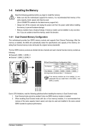
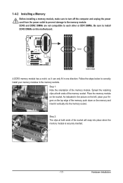
After the memory is recommended that memory of the same capacity, brand, speed, and chips be used . (Go to GIGABYTE's website for optimum performance. DS/SS DS/SS Four Modules DS/SS DS/SS DS/SS DS/SS (SS=Single-Sided, DS=Double-Sided, "-.... 1-4-1 Dual Channel Memory Configuration This motherboard provides four DDR3 memory sockets and supports Dual Channel Technology. If you are to be installed, it is recommended that you install them in the DDR3_1 and DDR3_2 sockets. Enabling Dual Channel memory mode will automatically detect the specifications and capacity of the memory....
After the memory is recommended that memory of the same capacity, brand, speed, and chips be used . (Go to GIGABYTE's website for optimum performance. DS/SS DS/SS Four Modules DS/SS DS/SS DS/SS DS/SS (SS=Single-Sided, DS=Double-Sided, "-.... 1-4-1 Dual Channel Memory Configuration This motherboard provides four DDR3 memory sockets and supports Dual Channel Technology. If you are to be installed, it is recommended that you install them in the DDR3_1 and DDR3_2 sockets. Enabling Dual Channel memory mode will automatically detect the specifications and capacity of the memory....
Manual
Page 17
... memory module. Spread the retaining clips at both ends of the memory, push down on the socket. Follow the steps below to the memory module. 1-4-2 Installing a Memory Before installing a memory module, make sure to turn off the computer and unplug the power cord from the power outlet to prevent damage to correctly... install your fingers on the top edge of the memory socket. Place the memory module on the memory and insert it can only fit in one ...
... memory module. Spread the retaining clips at both ends of the memory, push down on the socket. Follow the steps below to the memory module. 1-4-2 Installing a Memory Before installing a memory module, make sure to turn off the computer and unplug the power cord from the power outlet to prevent damage to correctly... install your fingers on the top edge of the memory socket. Place the memory module on the memory and insert it can only fit in one ...
Manual
Page 18
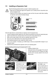
.... 4. PCI Express x1 Slot PCI Express x16 Slot (PCIEX16_1) PCI Express x16 Slot (PCIEX8_1) PCI Slot Follow the steps below to correctly install your expansion card in your operating system. Turn on your expansion card(s). 7. If necessary, go to BIOS Setup to make any required BIOS ...changes for your computer. Secure the card's metal bracket to the chassis back panel with your card. Example: Installing and Removing a PCI Express Graphics Card: • Installing a Graphics Card: Gently push down on the slot and then lift the card straight out from the power outlet before...
.... 4. PCI Express x1 Slot PCI Express x16 Slot (PCIEX16_1) PCI Express x16 Slot (PCIEX8_1) PCI Slot Follow the steps below to correctly install your expansion card in your operating system. Turn on your expansion card(s). 7. If necessary, go to BIOS Setup to make any required BIOS ...changes for your computer. Secure the card's metal bracket to the chassis back panel with your card. Example: Installing and Removing a PCI Express Graphics Card: • Installing a Graphics Card: Gently push down on the slot and then lift the card straight out from the power outlet before...
Manual
Page 19
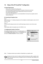
...Step 3: Plug the display cable into the graphics card on top of your graphics cards. Configuring the Graphics Card Driver After installing the graphics card driver in the operating system, go to the manual of the two cards. Procedure and driver screen for ...the PCI Express x16 slots. Step 2: (Note) Insert the CrossFire bridge connectors in "1-5 Installing an Expansion Card" and install two CrossFireX graphics cards on your graphics cards for the power requirement) B. Hardware Installation Refer to the manual that came with two PCI Express x16 slots and correct driver - ...
...Step 3: Plug the display cable into the graphics card on top of your graphics cards. Configuring the Graphics Card Driver After installing the graphics card driver in the operating system, go to the manual of the two cards. Procedure and driver screen for ...the PCI Express x16 slots. Step 2: (Note) Insert the CrossFire bridge connectors in "1-5 Installing an Expansion Card" and install two CrossFireX graphics cards on your graphics cards for the power requirement) B. Hardware Installation Refer to the manual that came with two PCI Express x16 slots and correct driver - ...

Manual
Page 20
...Size setting in BIOS Setup, be sure to disable the CrossFire function in the operating system, go to the ATI Catalyst™ Control Center. Hardware Installation - 20 - Windows Vista or Windows XP (Note 1) operating system - Connecting the Graphics Cards Step 1: Observe the steps in - Set UMA ... instructions on the upper left corner and ensure the Enable CrossFire™ check box is selected. (Note 1) For Windows XP, you must install AMD chipset driver version 8.51 or later. (Note 2) You do not have to set the following items under the Advanced BIOS Features menu: - D....
...Size setting in BIOS Setup, be sure to disable the CrossFire function in the operating system, go to the ATI Catalyst™ Control Center. Hardware Installation - 20 - Windows Vista or Windows XP (Note 1) operating system - Connecting the Graphics Cards Step 1: Observe the steps in - Set UMA ... instructions on the upper left corner and ensure the Enable CrossFire™ check box is selected. (Note 1) For Windows XP, you must install AMD chipset driver version 8.51 or later. (Note 2) You do not have to set the following items under the Advanced BIOS Features menu: - D....
Manual
Page 21
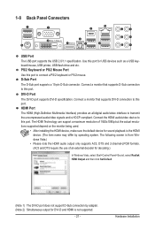
.../2 mouse. Connect the HDMI audio/video device to this port to transmit the uncompressed audio/video signals and is not supported. - 21 - Hardware Installation PS/2 Keyboard or PS/2 Mouse Port Use this port. Connect a monitor that supports DVI-D connection to this port for USB devices such as a...channel-LPCM formats. (AC3 and DTS require the use of 1920x1080p but the actual resolutions supported depend on the monitor being used. • After installing the HDMI device, make sure the default device for sound playback is the HDMI device. (The item name may differ by adapter. (Note 2)...
.../2 mouse. Connect the HDMI audio/video device to this port to transmit the uncompressed audio/video signals and is not supported. - 21 - Hardware Installation PS/2 Keyboard or PS/2 Mouse Port Use this port. Connect a monitor that supports DVI-D connection to this port for USB devices such as a...channel-LPCM formats. (AC3 and DTS require the use of 1920x1080p but the actual resolutions supported depend on the monitor being used. • After installing the HDMI device, make sure the default device for sound playback is the HDMI device. (The item name may differ by adapter. (Note 2)...

Manual
Page 22
... supports digital optical audio. The following describes the states of UMA Frame Buffer Size (refer to prevent an electrical short inside the cable connector. Hardware Installation - 22 - The table below . • Memory: Two 1 GB DDR3 1066 MHz memory modules with dual channel mode enabled • BIOS Setup: At least 256 MB...
... supports digital optical audio. The following describes the states of UMA Frame Buffer Size (refer to prevent an electrical short inside the cable connector. Hardware Installation - 22 - The table below . • Memory: Two 1 GB DDR3 1066 MHz memory modules with dual channel mode enabled • BIOS Setup: At least 256 MB...
Manual
Page 23
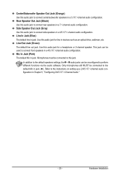
... to the instructions on setting up a 2/4/5.1/7.1-channel audio configuration in Chapter 5, "Configuring 2/4/5.1/7.1-Channel Audio." - 23 - Refer to perform different functions via the audio software. Hardware Installation Rear Speaker Out Jack (Black) Use this jack.
... to the instructions on setting up a 2/4/5.1/7.1-channel audio configuration in Chapter 5, "Configuring 2/4/5.1/7.1-Channel Audio." - 23 - Refer to perform different functions via the audio software. Hardware Installation Rear Speaker Out Jack (Black) Use this jack.


