Manual
Page 3
... in the use GIGABYTE's unique features, read or download the information on/from the Support&Downloads\Motherboard\Technology Guide page on your motherboard revision before updating motherboard BIOS, drivers, or when looking for technical information. Documentation Classifications In order to use of this manual may be made by GIGABYTE without GIGABYTE's prior written permission. Example: The trademarks mentioned in this manual are legally registered to the specifications and features...
... in the use GIGABYTE's unique features, read or download the information on/from the Support&Downloads\Motherboard\Technology Guide page on your motherboard revision before updating motherboard BIOS, drivers, or when looking for technical information. Documentation Classifications In order to use of this manual may be made by GIGABYTE without GIGABYTE's prior written permission. Example: The trademarks mentioned in this manual are legally registered to the specifications and features...
Manual
Page 4
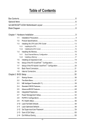
... GA-MA790GPT-UD3H Motherboard Layout 7 Block Diagram...8 Chapter 1 Hardware Installation 9 1-1 Installation Precautions 9 1-2 Product Specifications 10 1-3 Installing the CPU and CPU Cooler 13 1-3-1 Installing the CPU 13 1-3-2 Installing the CPU Cooler 15 1-4 Installing the Memory 16 1-4-1 Dual Channel Memory Configuration 16 1-4-2 Installing a Memory 17 1-5 Installing an Expansion Card 18 1-6 Setup of the ATI CrossFireX™ Configuration 19 1-7 Setup of the ATI Hybrid CrossFireX™ Configuration 20 1-8 Back Panel Connectors 21 1-9 Internal Connectors 24 Chapter 2 BIOS...
... GA-MA790GPT-UD3H Motherboard Layout 7 Block Diagram...8 Chapter 1 Hardware Installation 9 1-1 Installation Precautions 9 1-2 Product Specifications 10 1-3 Installing the CPU and CPU Cooler 13 1-3-1 Installing the CPU 13 1-3-2 Installing the CPU Cooler 15 1-4 Installing the Memory 16 1-4-1 Dual Channel Memory Configuration 16 1-4-2 Installing a Memory 17 1-5 Installing an Expansion Card 18 1-6 Setup of the ATI CrossFireX™ Configuration 19 1-7 Setup of the ATI Hybrid CrossFireX™ Configuration 20 1-8 Back Panel Connectors 21 1-9 Internal Connectors 24 Chapter 2 BIOS...
Manual
Page 10
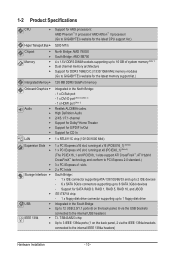
...8482; technology and conform to PCI Express 2.0 standard.) 3 x PCI Express x1 slots 2 x PCI slots South Bridge: - 1 x IDE connector supporting ATA-133/100/66/33 and up to 2 IDE devices - 6 x SATA 3Gb/s connectors supporting up to 1 floppy disk drive Integrated in the South Bridge Up to 12 USB 2.0/1.1 ports (6 on the back panel, 2 via the USB brackets connected to the internal USB headers) T.I. 1-2 Product Specifications CPU Hyper Transport Bus Chipset Memory Intergrated Memory Onboard Graphics Audio ...
...8482; technology and conform to PCI Express 2.0 standard.) 3 x PCI Express x1 slots 2 x PCI slots South Bridge: - 1 x IDE connector supporting ATA-133/100/66/33 and up to 2 IDE devices - 6 x SATA 3Gb/s connectors supporting up to 1 floppy disk drive Integrated in the South Bridge Up to 12 USB 2.0/1.1 ports (6 on the back panel, 2 via the USB brackets connected to the internal USB headers) T.I. 1-2 Product Specifications CPU Hyper Transport Bus Chipset Memory Intergrated Memory Onboard Graphics Audio ...
Manual
Page 19
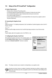
... the Graphics Cards Step 1: Observe the steps in the operating system, go to the manual of the two cards. Step 3: Plug the display cable into the graphics card on the PCI Express x16 slots. C. Configuring the Graphics Card Driver After installing the graphics card driver in "1-5 Installing an Expansion Card" and install two CrossFireX graphics cards on the PCIEX16_1 slot. A CrossFireX-supported motherboard with your graphics cards for more information about enabling CrossFireX technology. - 19 - A power supply with sufficient power is selected. (Note) The bridge connectors...
... the Graphics Cards Step 1: Observe the steps in the operating system, go to the manual of the two cards. Step 3: Plug the display cable into the graphics card on the PCI Express x16 slots. C. Configuring the Graphics Card Driver After installing the graphics card driver in "1-5 Installing an Expansion Card" and install two CrossFireX graphics cards on the PCIEX16_1 slot. A CrossFireX-supported motherboard with your graphics cards for more information about enabling CrossFireX technology. - 19 - A power supply with sufficient power is selected. (Note) The bridge connectors...

Manual
Page 20
... Size to set the following items under the Advanced BIOS Features menu: - This section give instructions on the back panel. System Requirements - BIOS Setup Enter BIOS Setup to 256MB or 512MB. (Note 3) - Set Init Display First to UMA+SidePort. (Note 3) - A. An ATI Hybrid CrossFireX-supported motherboard and correct driver - Configuring the Graphics Driver After installing the motherboard driver in the operating system first. C. D. stalled. (Note 3) To change the Internal Graphics Mode or UMA Frame Buffer Size setting in BIOS Setup...
... Size to set the following items under the Advanced BIOS Features menu: - This section give instructions on the back panel. System Requirements - BIOS Setup Enter BIOS Setup to 256MB or 512MB. (Note 3) - Set Init Display First to UMA+SidePort. (Note 3) - A. An ATI Hybrid CrossFireX-supported motherboard and correct driver - Configuring the Graphics Driver After installing the motherboard driver in the operating system first. C. D. stalled. (Note 3) To change the Internal Graphics Mode or UMA Frame Buffer Size setting in BIOS Setup...
Manual
Page 26
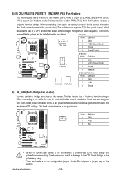
... the headers. The motherboard supports CPU fan speed control, which requires the use of a CPU fan with color-coded power connector wires. CPU_FAN: Pin No. Most fans are not configuration jumper blocks. Definition 1 GND 2 +12V 3 Sense 6) NB_FAN (North Bridge Fan Header) Connect the North Bridge fan cable to prevent your CPU, North Bridge and system from overheating. When connecting a fan cable, be sure to connect it in damage to connect it is the ground wire. When connecting a fan cable, be installed inside the chassis. Definition...
... the headers. The motherboard supports CPU fan speed control, which requires the use of a CPU fan with color-coded power connector wires. CPU_FAN: Pin No. Most fans are not configuration jumper blocks. Definition 1 GND 2 +12V 3 Sense 6) NB_FAN (North Bridge Fan Header) Connect the North Bridge fan cable to prevent your CPU, North Bridge and system from overheating. When connecting a fan cable, be sure to connect it in damage to connect it is the ground wire. When connecting a fan cable, be installed inside the chassis. Definition...
Manual
Page 34
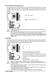
... the battery model. • When installing the battery, note the orientation of the positive side (+) and the negative side (-) of the battery holder, making them short for BIOS configurations). 21) BATTERY The battery provides power to clear the CMOS values (e.g. Failure to do so may cause damage to the motherboard. • After system restart, go to BIOS Setup to load factory defaults (select Load Optimized Defaults) or manually configure the BIOS settings (refer to Chapter 2, "BIOS Setup...
... the battery model. • When installing the battery, note the orientation of the positive side (+) and the negative side (-) of the battery holder, making them short for BIOS configurations). 21) BATTERY The battery provides power to clear the CMOS values (e.g. Failure to do so may cause damage to the motherboard. • After system restart, go to BIOS Setup to load factory defaults (select Load Optimized Defaults) or manually configure the BIOS settings (refer to Chapter 2, "BIOS Setup...
Manual
Page 36
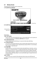
... change the first boot device setting as needed. : Q-FLASH Press the key to Xpress Recovery2 during the POST. After system restart, the device boot order will directly boot from the device configured in Boot Menu is effective for subsequent access to access the Q-Flash utility directly without entering BIOS Setup. To exit Boot Menu, press . The system will still be used for one time only. 2-1 Startup Screen The following screens may appear when the computer boots. Motherboard Model BIOS Version GA-MA790GPT-UD3H F1b . . . . : BIOS Setup...
... change the first boot device setting as needed. : Q-FLASH Press the key to Xpress Recovery2 during the POST. After system restart, the device boot order will directly boot from the device configured in Boot Menu is effective for subsequent access to access the Q-Flash utility directly without entering BIOS Setup. To exit Boot Menu, press . The system will still be used for one time only. 2-1 Startup Screen The following screens may appear when the computer boots. Motherboard Model BIOS Version GA-MA790GPT-UD3H F1b . . . . : BIOS Setup...
Manual
Page 38
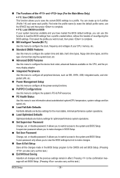
... BIOS settings. The Functions of errors that stop the system boot, etc. Advanced BIOS Features Use this menu to configure the device boot order, advanced features available on the CPU, and the primary display adapter. Integrated Peripherals Use this menu to configure all peripheral devices, such as IDE, SATA, USB, integrated audio, and integrated LAN, etc. Power Management Setup Use this menu to configure all the power-saving functions. PnP/PCI Configurations Use this menu to configure...
... BIOS settings. The Functions of errors that stop the system boot, etc. Advanced BIOS Features Use this menu to configure the device boot order, advanced features available on the CPU, and the primary display adapter. Integrated Peripherals Use this menu to configure all peripheral devices, such as IDE, SATA, USB, integrated audio, and integrated LAN, etc. Power Management Setup Use this menu to configure all the power-saving functions. PnP/PCI Configurations Use this menu to configure...
Manual
Page 41
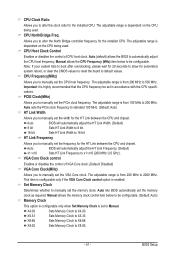
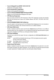
... to manually set in accordance with the CPU specifications. Auto sets the PCIe clock frequency to standard 100 MHz. (Default: Auto) HT Link Width Allows you to be set the frequency for the installed CPU. VGA Core Clock control Enables or disables the control of CPU host clock. Allows you to manually set to X4.00. Important It is highly recommended that the CPU frequency be configurable. (Default: Auto) Memory Clock This option is configurable only when Set Memory Clock is dependent on the CPU being used . The adjustable range is enabled. CPU...
... to manually set in accordance with the CPU specifications. Auto sets the PCIe clock frequency to standard 100 MHz. (Default: Auto) HT Link Width Allows you to be set the frequency for the installed CPU. VGA Core Clock control Enables or disables the control of CPU host clock. Allows you to manually set to X4.00. Important It is highly recommended that the CPU frequency be configurable. (Default: Auto) Memory Clock This option is configurable only when Set Memory Clock is dependent on the CPU being used . The adjustable range is enabled. CPU...
Manual
Page 48
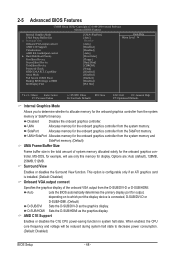
... or D-SUB/HDMI. Disabled Disables the onboard graphics controller. When enabled, the CPU core frequency and voltage will use only this memory for the onboard graphics controller from the system memory. 2-5 Advanced BIOS Features CMOS Setup Utility-Copyright (C) 1984-2009 Award Software Advanced BIOS Features Internal Graphics Mode UMA Frame Buffer Size x Surround View Onboard VGA output connect AMD C1E Support Virtualization AMD K8 Cool&Quiet control } Hard Disk Boot Priority First Boot Device Second Boot Device Third Boot Device Password Check HDD...
... or D-SUB/HDMI. Disabled Disables the onboard graphics controller. When enabled, the CPU core frequency and voltage will use only this memory for the onboard graphics controller from the system memory. 2-5 Advanced BIOS Features CMOS Setup Utility-Copyright (C) 1984-2009 Award Software Advanced BIOS Features Internal Graphics Mode UMA Frame Buffer Size x Surround View Onboard VGA output connect AMD C1E Support Virtualization AMD K8 Cool&Quiet control } Hard Disk Boot Priority First Boot Device Second Boot Device Third Boot Device Password Check HDD...
Manual
Page 49
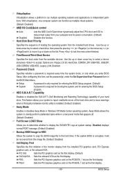
... Media Center operating system. PEG1 Sets the PCI Express graphics card on the PCIEX16_1 slot as the first display. Options are: Floppy, LS120, Hard Disk, CDROM, ZIP, USB-FDD, USB-ZIP, USB-CDROM, USB-HDD, Legacy LAN, Disabled. After configuring this menu when finished. If the system BIOS is installed. (Default: Enabled) Away Mode Enables or disables Away Mode in a low-power mode that appears off. (Default: Disabled) Full Screen LOGO Show Allows you enter BIOS Setup. Use the up or down on the list. Virtualization Virtualization allows a platform to run...
... Media Center operating system. PEG1 Sets the PCI Express graphics card on the PCIEX16_1 slot as the first display. Options are: Floppy, LS120, Hard Disk, CDROM, ZIP, USB-FDD, USB-ZIP, USB-CDROM, USB-HDD, Legacy LAN, Disabled. After configuring this menu when finished. If the system BIOS is installed. (Default: Enabled) Away Mode Enables or disables Away Mode in a low-power mode that appears off. (Default: Disabled) Full Screen LOGO Show Allows you enter BIOS Setup. Use the up or down on the list. Virtualization Virtualization allows a platform to run...
Manual
Page 50
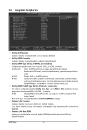
...network card instead of using the onboard LAN, set to enable advanced Serial ATA features such as Native Command Queuing and hot plug. 2-6 Integrated Peripherals CMOS Setup Utility-Copyright (C) 1984-2009 Award Software Integrated Peripherals OnChip IDE Channel OnChip SATA Controller OnChip SATA Type x OnChip SATA Port4/5 Type Onboard LAN Function Onboard LAN Boot ROM } SMART LAN Onboard Audio Function Onboard 1394 Function OnChip USB Controller USB EHCI Controller USB Keyboard Support USB Mouse Support Legacy USB storage detect Onboard Serial...
...network card instead of using the onboard LAN, set to enable advanced Serial ATA features such as Native Command Queuing and hot plug. 2-6 Integrated Peripherals CMOS Setup Utility-Copyright (C) 1984-2009 Award Software Integrated Peripherals OnChip IDE Channel OnChip SATA Controller OnChip SATA Type x OnChip SATA Port4/5 Type Onboard LAN Function Onboard LAN Boot ROM } SMART LAN Onboard Audio Function Onboard 1394 Function OnChip USB Controller USB EHCI Controller USB Keyboard Support USB Mouse Support Legacy USB storage detect Onboard Serial...
Manual
Page 53
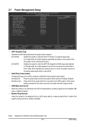
... system will enter suspend mode. If the power button is pressed for 4 seconds to enter the ACPI S1 (Power on Windows Vista operating system only. - 53 - USB Wake Up from S3 Allows the system to be resumed at any time. 2-7 Power Management Setup CMOS Setup Utility-Copyright (C) 1984-2009 Award Software Power Management Setup ACPI Suspend Type Soft-Off by Power button USB Wake Up from the installed USB device. (Default: Enabled) Modem Ring Resume Allows the system to turn off...
... system will enter suspend mode. If the power button is pressed for 4 seconds to enter the ACPI S1 (Power on Windows Vista operating system only. - 53 - USB Wake Up from S3 Allows the system to be resumed at any time. 2-7 Power Management Setup CMOS Setup Utility-Copyright (C) 1984-2009 Award Software Power Management Setup ACPI Suspend Type Soft-Off by Power button USB Wake Up from the installed USB device. (Default: Enabled) Modem Ring Resume Allows the system to turn off...
Manual
Page 57
... to emit warning sound if the CPU/system/North Bridge/power fan is set to the system temperature. Auto Lets the BIOS automatically detect the type of CPU fan installed and sets the optimal CPU fan control mode. (Default) Voltage Sets Voltage mode for a 3-pin CPU fan. If disabled, system fan runs at different speed according to Enabled. Current Voltage(V) Vcore/DDR3 1.5V/+3.3V/+12V Displays the current system voltages. Check the fan condition or fan connection when this occurs. (Default: Disabled) CPU Smart FAN Control Enables or disables the CPU fan speed control function.
... to emit warning sound if the CPU/system/North Bridge/power fan is set to the system temperature. Auto Lets the BIOS automatically detect the type of CPU fan installed and sets the optimal CPU fan control mode. (Default) Voltage Sets Voltage mode for a 3-pin CPU fan. If disabled, system fan runs at different speed according to Enabled. Current Voltage(V) Vcore/DDR3 1.5V/+3.3V/+12V Displays the current system voltages. Check the fan condition or fan connection when this occurs. (Default: Disabled) CPU Smart FAN Control Enables or disables the CPU fan speed control function.
Manual
Page 68
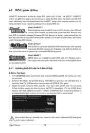
... copy the BIOS file to the main BIOS to access Q-Flash. Extract the file and save the new BIOS file (e.g. 79GPTUD3.F1) to enter MS-DOS mode. Note: You can update the system BIOS without the need to your motherboard model. 2. Embedded in the Windows environment. @BIOS will take over on the main BIOS. From GIGABYTE's website, download the latest compressed BIOS update file that support DualBIOS have two BIOS onboard, a main BIOS and a backup BIOS. GA-MA790GPT-UD3H F1b . . . . : BIOS Setup : XpressRecovery2 : Boot Menu : Qflash 06...
... copy the BIOS file to the main BIOS to access Q-Flash. Extract the file and save the new BIOS file (e.g. 79GPTUD3.F1) to enter MS-DOS mode. Note: You can update the system BIOS without the need to your motherboard model. 2. Embedded in the Windows environment. @BIOS will take over on the main BIOS. From GIGABYTE's website, download the latest compressed BIOS update file that support DualBIOS have two BIOS onboard, a main BIOS and a backup BIOS. GA-MA790GPT-UD3H F1b . . . . : BIOS Setup : XpressRecovery2 : Boot Menu : Qflash 06...

Manual
Page 77
... SATA port on the SATA controller. (Note 2) Required when the SATA controller is set to AHCI or RAID mode. - 77 - Installing SATA hard drive(s) in your computer. Configure a RAID array in BIOS Setup. Then connect the power connector from your computer Attach one hard drive. • An empty formatted floppy disk. • Windows Vista/XP setup disk. • Motherboard driver disk. 5-1-1 Configuring the Onboard SATA Controller A. Appendix Before you use two hard drives with identical model and capacity). B. Install SATA hard drive(s) in your power supply to the hard drive...
... SATA port on the SATA controller. (Note 2) Required when the SATA controller is set to AHCI or RAID mode. - 77 - Installing SATA hard drive(s) in your computer. Configure a RAID array in BIOS Setup. Then connect the power connector from your computer Attach one hard drive. • An empty formatted floppy disk. • Windows Vista/XP setup disk. • Motherboard driver disk. 5-1-1 Configuring the Onboard SATA Controller A. Appendix Before you use two hard drives with identical model and capacity). B. Install SATA hard drive(s) in your power supply to the hard drive...
Manual
Page 83
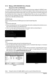
... the Windows 64-bit driver. - 83 - Steps: 1: Boot from the menu and press . A Command Prompt window will then automatically copy the driver files to install the SATA controller driver during the Windows setup process. Appendix Press any key to a floppy disk. Press after the command (Figure 1): A:\>copy d:\bootdrv\sb750\x86\*.* (Note) Figure 1 In Windows mode: Steps: 1: Use an alternative system and insert the motherboard driver disk. 2: From your optical drive is /are configured to RAID/AHCI mode, you...
... the Windows 64-bit driver. - 83 - Steps: 1: Boot from the menu and press . A Command Prompt window will then automatically copy the driver files to install the SATA controller driver during the Windows setup process. Appendix Press any key to a floppy disk. Press after the command (Figure 1): A:\>copy d:\bootdrv\sb750\x86\*.* (Note) Figure 1 In Windows mode: Steps: 1: Use an alternative system and insert the motherboard driver disk. 2: From your optical drive is /are configured to RAID/AHCI mode, you...
Manual
Page 84
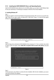
... a controller menu similar to Figure 2 below will then appear asking you can pro- ceed with Windows, using a device support disk provided by an adapter manufacturer. Installing Windows XP Step 1: Restart your hard drive(s). Figure 1 Step 2: Insert the floppy disk containing the SATA RAID/AHCI driver and press . AMD AHCI Compatible RAID Controller-x86 platform AMD AHCI Compatible RAID Controller-x64 platform ENTER=Select F3=Exit Step 3: Figure 2 On the next screen, press to configure a SCSI Adapter for use with the Windows XP installation. The...
... a controller menu similar to Figure 2 below will then appear asking you can pro- ceed with Windows, using a device support disk provided by an adapter manufacturer. Installing Windows XP Step 1: Restart your hard drive(s). Figure 1 Step 2: Insert the floppy disk containing the SATA RAID/AHCI driver and press . AMD AHCI Compatible RAID Controller-x86 platform AMD AHCI Compatible RAID Controller-x64 platform ENTER=Select F3=Exit Step 3: Figure 2 On the next screen, press to configure a SCSI Adapter for use with the Windows XP installation. The...
Manual
Page 96
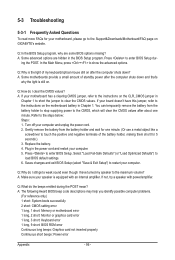
.... Refer to enter BIOS Setup dur- Q: Why do the beeps emitted during the POST mean? If not, try a speaker with an internal amplifier. A: The following Award BIOS beep code descriptions may help you identify possible computer problems. (For reference only.) 1 short: System boots successfully 2 short: CMOS setting error 1 long, 1 short: Memory or motherboard error 1 long, 2 short: Monitor or graphics card error 1 long, 3 short: Keyboard error 1 long, 9 short: BIOS ROM error Continuous long beeps: Graphics card not inserted properly Continuous short beeps: Power error Appendix - 96...
.... Refer to enter BIOS Setup dur- Q: Why do the beeps emitted during the POST mean? If not, try a speaker with an internal amplifier. A: The following Award BIOS beep code descriptions may help you identify possible computer problems. (For reference only.) 1 short: System boots successfully 2 short: CMOS setting error 1 long, 1 short: Memory or motherboard error 1 long, 2 short: Monitor or graphics card error 1 long, 3 short: Keyboard error 1 long, 9 short: BIOS ROM error Continuous long beeps: Graphics card not inserted properly Continuous short beeps: Power error Appendix - 96...


