Manual
Page 4
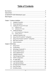
Table of Contents Box Contents...6 Optional Items...6 GA-MA790GPT-UD3H Motherboard Layout 7 Block Diagram...8 Chapter 1 Hardware Installation 9 1-1 Installation Precautions 9 1-2 Product Specifications 10 1-3 Installing the CPU and CPU Cooler 13 1-3-1 Installing the CPU 13 1-3-2 Installing the CPU Cooler 15 1-4 Installing the Memory 16 1-4-1 Dual Channel Memory Configuration 16 1-4-2 Installing a Memory 17 1-5 Installing an Expansion Card 18 1-6 Setup of...
Table of Contents Box Contents...6 Optional Items...6 GA-MA790GPT-UD3H Motherboard Layout 7 Block Diagram...8 Chapter 1 Hardware Installation 9 1-1 Installation Precautions 9 1-2 Product Specifications 10 1-3 Installing the CPU and CPU Cooler 13 1-3-1 Installing the CPU 13 1-3-2 Installing the CPU Cooler 15 1-4 Installing the Memory 16 1-4-1 Dual Channel Memory Configuration 16 1-4-2 Installing a Memory 17 1-5 Installing an Expansion Card 18 1-6 Setup of...

Manual
Page 8
... 1 PCI Express x16 (Note 1) 2 PCI Express x8 (Note 1) PCIe CLK (100 MHz) AM3 CPU CPU CLK+/- (200 MHz) DDR3 1666(O.C.)/1333/1066 MHz Dual Channel Memory Hyper Transport 3.0 Switch PCI Express Bus x16 x1 x1 x1 x1 PCIe CLK (100 MHz) 3 PCI Express x1 RTL8111C RJ45 LAN 6 SATA 3Gb/s ATA-133.../100/66/33 IDE Channel PCI Bus TSB43AB23 3 IEEE 1394a AMD 790GX GFX CLK (100 MHz) D-Sub DVI-D or HDMI (Note 2) DDR3 SidePort Memory 12 USB Ports AMD SB750 Dual BIOS CODEC LPC Bus IT8718 Floppy COM Port PS/2 KB or Mouse Surround Speaker Out Center/Subwoofer Speaker Out...
... 1 PCI Express x16 (Note 1) 2 PCI Express x8 (Note 1) PCIe CLK (100 MHz) AM3 CPU CPU CLK+/- (200 MHz) DDR3 1666(O.C.)/1333/1066 MHz Dual Channel Memory Hyper Transport 3.0 Switch PCI Express Bus x16 x1 x1 x1 x1 PCIe CLK (100 MHz) 3 PCI Express x1 RTL8111C RJ45 LAN 6 SATA 3Gb/s ATA-133.../100/66/33 IDE Channel PCI Bus TSB43AB23 3 IEEE 1394a AMD 790GX GFX CLK (100 MHz) D-Sub DVI-D or HDMI (Note 2) DDR3 SidePort Memory 12 USB Ports AMD SB750 Dual BIOS CODEC LPC Bus IT8718 Floppy COM Port PS/2 KB or Mouse Surround Speaker Out Center/Subwoofer Speaker Out...
Manual
Page 9
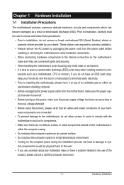
... place the computer system in a high-temperature environment. • Turning on the computer power during the installation process can become damaged as a motherboard, CPU or memory.
... place the computer system in a high-temperature environment. • Turning on the computer power during the installation process can become damaged as a motherboard, CPU or memory.
Manual
Page 10
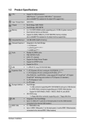
...and up to 2 IDE devices - 6 x SATA 3Gb/s connectors supporting up to 16 GB of system memory (Note 1) Dual channel memory architecture Support for DDR3 1666(O.C.)/1333/1066 MHz memory modules (Go to GIGABYTE's website for the latest CPU support list.) 5200 MT/s North Bridge: AMD 790GX South Bridge: AMD SB750 ... 1394 Support for AM3 processors: AMD Phenom™ II processor/ AMD Athlon™ II processor/ (Go to GIGABYTE's website for the latest memory support list.) 128 MB DDR3 SidePort memory Integrated in the South Bridge Up to 12 USB 2.0/1.1 ports (6 on the back panel, 2 via the USB...
...and up to 2 IDE devices - 6 x SATA 3Gb/s connectors supporting up to 16 GB of system memory (Note 1) Dual channel memory architecture Support for DDR3 1666(O.C.)/1333/1066 MHz memory modules (Go to GIGABYTE's website for the latest CPU support list.) 5200 MT/s North Bridge: AMD 790GX South Bridge: AMD SB750 ... 1394 Support for AM3 processors: AMD Phenom™ II processor/ AMD Athlon™ II processor/ (Go to GIGABYTE's website for the latest memory support list.) 128 MB DDR3 SidePort memory Integrated in the South Bridge Up to 12 USB 2.0/1.1 ports (6 on the back panel, 2 via the USB...

Manual
Page 12
... control function is to be installed, be sure to Windows Vista/XP 32-bit operating system limitation, when more than 4 GB of physical memory is installed, the actual memory size displayed will be less than 4 GB. (Note 2) The DVI-D port does not support D-Sub connection by adapter. (Note 3) Simultaneous output for Microsoft...
... control function is to be installed, be sure to Windows Vista/XP 32-bit operating system limitation, when more than 4 GB of physical memory is installed, the actual memory size displayed will be less than 4 GB. (Note 2) The DVI-D port does not support D-Sub connection by adapter. (Note 3) Simultaneous output for Microsoft...
Manual
Page 13
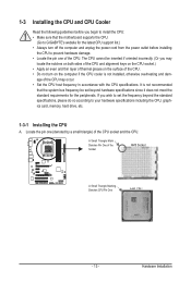
If you wish to set beyond the standard specifications, please do so according to your hardware specifications including the CPU, graphics card, memory, hard drive, etc. 1-3-1 Installing the CPU A. age of the CPU may locate the notches on both sides of the CPU and alignment keys ... be inserted if oriented incorrectly. (Or you begin to install the CPU: • Make sure that the motherboard supports the CPU. (Go to GIGABYTE's website for the peripherals. The CPU cannot be set the frequency beyond hardware specifications since it does not meet the standard requirements for the latest...
If you wish to set beyond the standard specifications, please do so according to your hardware specifications including the CPU, graphics card, memory, hard drive, etc. 1-3-1 Installing the CPU A. age of the CPU may locate the notches on both sides of the CPU and alignment keys ... be inserted if oriented incorrectly. (Or you begin to install the CPU: • Make sure that the motherboard supports the CPU. (Go to GIGABYTE's website for the peripherals. The CPU cannot be set the frequency beyond hardware specifications since it does not meet the standard requirements for the latest...
Manual
Page 16
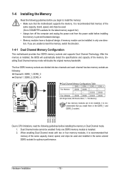
... DS/SS DS/SS - - - - - - - - It is recommended that memory of the same capacity, brand, speed, and chips be used . (Go to GIGABYTE's website for optimum performance. After the memory is installed. 2. Enabling Dual Channel memory mode will automatically detect the specifications and capacity of the memory. Dual Channel mode cannot be enabled if only one...
... DS/SS DS/SS - - - - - - - - It is recommended that memory of the same capacity, brand, speed, and chips be used . (Go to GIGABYTE's website for optimum performance. After the memory is installed. 2. Enabling Dual Channel memory mode will automatically detect the specifications and capacity of the memory. Dual Channel mode cannot be enabled if only one...
Manual
Page 17
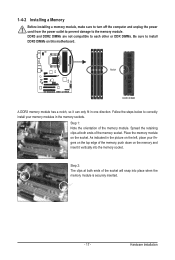
... so it vertically into place when the memory module is securely inserted. - 17 - Place the memory module on the memory and insert it can only fit in the picture on the left, place your memory modules in the memory sockets. 1-4-2 Installing a Memory Before installing a memory module, make sure to turn off the...correctly install your fingers on the top edge of the memory socket. As indicated in one direction. Follow the steps below to the memory module. Step 1: Note the orientation of the socket will snap into the memory socket. Hardware Installation DDR3 and DDR2 DIMMs are not ...
... so it vertically into place when the memory module is securely inserted. - 17 - Place the memory module on the memory and insert it can only fit in the picture on the left, place your memory modules in the memory sockets. 1-4-2 Installing a Memory Before installing a memory module, make sure to turn off the...correctly install your fingers on the top edge of the memory socket. As indicated in one direction. Follow the steps below to the memory module. Step 1: Note the orientation of the socket will snap into the memory socket. Hardware Installation DDR3 and DDR2 DIMMs are not ...

Manual
Page 22
The table below . • Memory: Two 1 GB DDR3 1066 MHz memory modules with dual channel mode enabled • BIOS Setup: At least 256 MB of the LAN port LEDs. Playback of HD DVD and Blu-ray ...
The table below . • Memory: Two 1 GB DDR3 1066 MHz memory modules with dual channel mode enabled • BIOS Setup: At least 256 MB of the LAN port LEDs. Playback of HD DVD and Blu-ray ...
Manual
Page 38
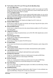
... Without Saving Abandon all the power-saving functions. PnP/PCI Configurations Use this menu to load the BIOS settings from BIOS If your CPU, memory, etc. Standard CMOS Features Use this menu to configure the system time and date, hard drive types, floppy disk drive types, and the type...
... Without Saving Abandon all the power-saving functions. PnP/PCI Configurations Use this menu to load the BIOS settings from BIOS If your CPU, memory, etc. Standard CMOS Features Use this menu to configure the system time and date, hard drive types, floppy disk drive types, and the type...
Manual
Page 39
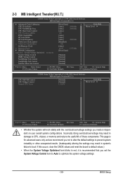
... CPU Frequency(MHz) PCIE Clock(MHz) HT Link Width HT Link Frequency VGA Core Clock control x VGA Core Clock(MHz) Set Memory Clock x Memory Clock } DRAM Configuration ******** System Voltage Optimized ******** System Voltage Control DDR3 Voltage Control NorthBridge Volt Control SouthBridge Volt Control SidePort Mem Volt ... the board to default values.) • When the System Voltage Optimized item blinks in damage to CPU, chipset, or memory and reduce the useful life of these components. This page is for advanced users only and we recommend you made is ...
... CPU Frequency(MHz) PCIE Clock(MHz) HT Link Width HT Link Frequency VGA Core Clock control x VGA Core Clock(MHz) Set Memory Clock x Memory Clock } DRAM Configuration ******** System Voltage Optimized ******** System Voltage Control DDR3 Voltage Control NorthBridge Volt Control SouthBridge Volt Control SidePort Mem Volt ... the board to default values.) • When the System Voltage Optimized item blinks in damage to CPU, chipset, or memory and reduce the useful life of these components. This page is for advanced users only and we recommend you made is ...
Manual
Page 41
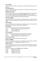
...CPU Host Clock Control Enables or disables the control of VGA Core clock. (Default: Disabled) VGA Core Clock(MHz) Allows you to manually set the memory clock as required. Auto BIOS will automatically adjust the HT Link Width. (Default) 8 bit Sets HT Link Width to 8 bit. 16 bit Sets...100 MHz. (Default: Auto) HT Link Width Allows you to alter the North Bridge controller frequency for the installed CPU. X6.66 Sets Memory Clock to X4.00. CPU Clock Ratio Allows you to manually set in accordance with the CPU specifications. The adjustable range is highly recommended ...
...CPU Host Clock Control Enables or disables the control of VGA Core clock. (Default: Disabled) VGA Core Clock(MHz) Allows you to manually set the memory clock as required. Auto BIOS will automatically adjust the HT Link Width. (Default) 8 bit Sets HT Link Width to 8 bit. 16 bit Sets...100 MHz. (Default: Auto) HT Link Width Allows you to alter the North Bridge controller frequency for the installed CPU. X6.66 Sets Memory Clock to X4.00. CPU Clock Ratio Allows you to manually set in accordance with the CPU specifications. The adjustable range is highly recommended ...
Manual
Page 42
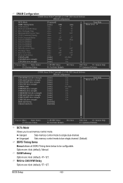
... DIMM2 x Trfc1 for DIMM3 x Trfc3 for DIMM4 x Write Recovery Time x Precharge Time x Row Cycle Time x RAS to be configurable. Auto -- Unganged Sets memory control mode to two single-channel. (Default) DDR3 Timing Items Manual allows all DDR3 Timing items below to RAS Delay CHA ProcOdt CHA DQS drive...- 42 - Auto -- RAS to CAS R/W Delay Options are : Auto (default), 4T~12T. CAS# latency Options are : Auto (default), 5T~12T. Ganged Sets memory control mode to set memory control mode. Options are: Auto (default), Manual. Auto 5T Auto 90ns Auto --
... DIMM2 x Trfc1 for DIMM3 x Trfc3 for DIMM4 x Write Recovery Time x Precharge Time x Row Cycle Time x RAS to be configurable. Auto -- Unganged Sets memory control mode to two single-channel. (Default) DDR3 Timing Items Manual allows all DDR3 Timing items below to RAS Delay CHA ProcOdt CHA DQS drive...- 42 - Auto -- RAS to CAS R/W Delay Options are : Auto (default), 4T~12T. CAS# latency Options are : Auto (default), 5T~12T. Ganged Sets memory control mode to set memory control mode. Options are: Auto (default), Manual. Auto 5T Auto 90ns Auto --
Manual
Page 44
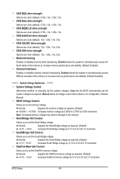
...lets the BIOS automatically set the North Bridge voltage. Enabled allows the system to simultaneously access different banks of the memory to increase memory performance and stability. (Default: Enabled) ******** System Voltage Optimized ******** System Voltage Control Determines whether to set the ...Bridge voltage by -0.1V to 0.3V at 0.05V increment. Normal Supplies the North Bridge voltage as required. (Default) +0.050V ~ +0.750V Increases memory voltage by 0.1V to 0.2V at 0.1V increment. CHB Add/Cmd drive strength Options are : Auto (default), 0.75x, 1.0x, 1.25x...
...lets the BIOS automatically set the North Bridge voltage. Enabled allows the system to simultaneously access different banks of the memory to increase memory performance and stability. (Default: Enabled) ******** System Voltage Optimized ******** System Voltage Control Determines whether to set the ...Bridge voltage by -0.1V to 0.3V at 0.05V increment. Normal Supplies the North Bridge voltage as required. (Default) +0.050V ~ +0.750V Increases memory voltage by 0.1V to 0.2V at 0.1V increment. CHB Add/Cmd drive strength Options are : Auto (default), 0.75x, 1.0x, 1.25x...
Manual
Page 46
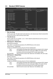
... 3 Master } IDE Channel 3 Slave [None] [None] [None] [None] [None] [None] [None] [None] Drive A Floppy 3 Mode Support [1.44M, 3.5"] [Disabled] Halt On [All, But Keyboard] Base Memory Extended Memory 640K 510M Move Enter: Select F5: Previous Values +/-/PU/PD: Value F10: Save F6: Fail-Safe Defaults ESC: Exit F1: General Help F7: Optimized Defaults...
... 3 Master } IDE Channel 3 Slave [None] [None] [None] [None] [None] [None] [None] [None] Drive A Floppy 3 Mode Support [1.44M, 3.5"] [Disabled] Halt On [All, But Keyboard] Base Memory Extended Memory 640K 510M Move Enter: Select F5: Previous Values +/-/PU/PD: Value F10: Save F6: Fail-Safe Defaults ESC: Exit F1: General Help F7: Optimized Defaults...
Manual
Page 47
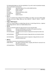
...640 KB will not stop for a floppy disk drive error but stop for all other errors. Head Number of cylinders. Sector Number of extended memory. - 47 - All, But Disk/Key The system boot will not stop for a keyboard or a floppy disk drive error but stop for... MS-DOS operating system. BIOS Setup Options are determined by the BIOS POST. Memory These fields are read-only and are : None, 360K/5.25", 1.2M/5.25", 720K/3.5", 1.44M/3.5", 2.88M/3.5". Extended Memory The amount of sectors. Capacity Approximate capacity of floppy disk drive installed in your...
...640 KB will not stop for a floppy disk drive error but stop for all other errors. Head Number of cylinders. Sector Number of extended memory. - 47 - All, But Disk/Key The system boot will not stop for a keyboard or a floppy disk drive error but stop for... MS-DOS operating system. BIOS Setup Options are determined by the BIOS POST. Memory These fields are read-only and are : None, 360K/5.25", 1.2M/5.25", 720K/3.5", 1.44M/3.5", 2.88M/3.5". Extended Memory The amount of sectors. Capacity Approximate capacity of floppy disk drive installed in your...
Manual
Page 48
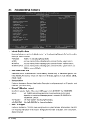
... the display device is the total amount of the onboard VGA output from the system memory or SidePort memory. When enabled, the CPU core frequency and voltage will use only this memory for the onboard graphics controller from the D-SUB/DVI-D or D-SUB/HDMI. SidePort ...ATI graphics card is installed. (Default: Disabled) Onboard VGA output connect Specifies the graphics display of system memory allocated solely for the onboard graphics controller from the system memory and SidePort memory. (Default) UMA Frame Buffer Size Frame buffer size is connected, D-SUB/DVI-D or D-SUB/HDMI....
... the display device is the total amount of the onboard VGA output from the system memory or SidePort memory. When enabled, the CPU core frequency and voltage will use only this memory for the onboard graphics controller from the D-SUB/DVI-D or D-SUB/HDMI. SidePort ...ATI graphics card is installed. (Default: Disabled) Onboard VGA output connect Specifies the graphics display of system memory allocated solely for the onboard graphics controller from the system memory and SidePort memory. (Default) UMA Frame Buffer Size Frame buffer size is connected, D-SUB/DVI-D or D-SUB/HDMI....

Manual
Page 54
... of the system after the return of Month): Turn on the system at least 1A on the +5VSB lead. Power-On by a wake-up event. Memory The system returns to its last known awake state upon the return of the AC power. (Default) Full-On The system is set the date...
... of the system after the return of Month): Turn on the system at least 1A on the +5VSB lead. Power-On by a wake-up event. Memory The system returns to its last known awake state upon the return of the AC power. (Default) Full-On The system is set the date...
Manual
Page 65
... and so forth. System Requirements: • At least 512 MB of it . Installation and Configuration: Turn on your system data and perform restoration of system memory • VESA compatible graphics card • Windows XP with Xpress Recovery cannot be restored using Xpress Recovery2. • USB hard drives are attached to boot...
... and so forth. System Requirements: • At least 512 MB of it . Installation and Configuration: Turn on your system data and perform restoration of system memory • VESA compatible graphics card • Windows XP with Xpress Recovery cannot be restored using Xpress Recovery2. • USB hard drives are attached to boot...
Manual
Page 72
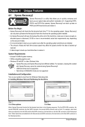
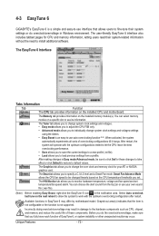
...GIGABYTE's EasyTune 6 is a simple and easy-to-use interface that allows users to fine-tune their system-related information without the need to install additional software. After restart, the system will operate with the optimum overclocking configuration after restart. The Graphics tab allows you to change the core clock and memory... experiments all sorts of EasyTune 6, or system instability or other unexpected results may occur. You can select memory module on a specific slot to monitor hardware temperature, voltage and fan speed and set . Unique Features ...
...GIGABYTE's EasyTune 6 is a simple and easy-to-use interface that allows users to fine-tune their system-related information without the need to install additional software. After restart, the system will operate with the optimum overclocking configuration after restart. The Graphics tab allows you to change the core clock and memory... experiments all sorts of EasyTune 6, or system instability or other unexpected results may occur. You can select memory module on a specific slot to monitor hardware temperature, voltage and fan speed and set . Unique Features ...


