Manual
Page 1
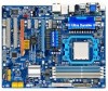
GA-MA790GPT-UD3H AM3 socket motherboard for AMD Phenom™ II processor/AMD Athlon™ II processor User's Manual Rev. 1002 12ME-MA79PT3-1002R
GA-MA790GPT-UD3H AM3 socket motherboard for AMD Phenom™ II processor/AMD Athlon™ II processor User's Manual Rev. 1002 12ME-MA79PT3-1002R
Manual
Page 3
... 2009 GIGA-BYTE TECHNOLOGY CO., LTD. The trademarks mentioned in this manual may be reproduced, copied, translated, transmitted, or published in this manual may be made by any form or by GIGABYTE without GIGABYTE's prior written permission. Changes to the specifications and features in any... example, "REV: 1.0" means the revision of GIGABYTE. Disclaimer Information in the use of this product, GIGABYTE provides the following types of documentations: For quick set-up of this manual are legally registered to use GIGABYTE's unique features, read or download the information on...
... 2009 GIGA-BYTE TECHNOLOGY CO., LTD. The trademarks mentioned in this manual may be reproduced, copied, translated, transmitted, or published in this manual may be made by any form or by GIGABYTE without GIGABYTE's prior written permission. Changes to the specifications and features in any... example, "REV: 1.0" means the revision of GIGABYTE. Disclaimer Information in the use of this product, GIGABYTE provides the following types of documentations: For quick set-up of this manual are legally registered to use GIGABYTE's unique features, read or download the information on...
Manual
Page 5
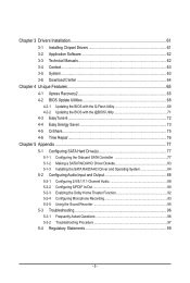
Chapter 3 Drivers Installation 61 3-1 Installing Chipset Drivers 61 3-2 Application Software 62 3-3 Technical Manuals 62 3-4 Contact...63 3-5 System...63 3-6 Download Center 64 Chapter 4 Unique Features 65 4-1 Xpress Recovery2 65 4-2 BIOS Update Utilities 68 4-2-1 Updating the BIOS with the Q-Flash ...
Chapter 3 Drivers Installation 61 3-1 Installing Chipset Drivers 61 3-2 Application Software 62 3-3 Technical Manuals 62 3-4 Contact...63 3-5 System...63 3-6 Download Center 64 Chapter 4 Unique Features 65 4-1 Xpress Recovery2 65 4-2 BIOS Update Utilities 68 4-2-1 Updating the BIOS with the Q-Flash ...
Manual
Page 6
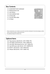
... power cable (Part No. 12CF1-2SERPW-0*R) S/PDIF In cable (Part No. 12CR1-1SPDIN-0*R) COM port cable (Part No. 12CF1-1CM001-3*R) - 6 - Box Contents GA-MA790GPT-UD3H motherboard Motherboard driver disk User's Manual Quick Installation Guide One IDE cable Two SATA 3Gb/s cables I/O Shield • The box contents above are subject to change without notice. •...
... power cable (Part No. 12CF1-2SERPW-0*R) S/PDIF In cable (Part No. 12CR1-1SPDIN-0*R) COM port cable (Part No. 12CF1-1CM001-3*R) - 6 - Box Contents GA-MA790GPT-UD3H motherboard Motherboard driver disk User's Manual Quick Installation Guide One IDE cable Two SATA 3Gb/s cables I/O Shield • The box contents above are subject to change without notice. •...
Manual
Page 9
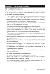
... or connectors. • It is best to wear an electrostatic discharge (ESD) wrist strap when handling electronic com- Prior to installation, carefully read the user's manual and follow these procedures: • Prior to the use of electrostatic discharge (ESD).
... or connectors. • It is best to wear an electrostatic discharge (ESD) wrist strap when handling electronic com- Prior to installation, carefully read the user's manual and follow these procedures: • Prior to the use of electrostatic discharge (ESD).
Manual
Page 15
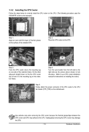
... the steps below to correctly install the CPU cooler on the CPU. (The following procedure uses the GIGABYTE cooler as the picture above shows) to lock into place. (Refer to your CPU cooler installation manual for instructions on installing the cooler.) Step 5: Finally, attach the power connector of the CPU cooler to...
... the steps below to correctly install the CPU cooler on the CPU. (The following procedure uses the GIGABYTE cooler as the picture above shows) to lock into place. (Refer to your CPU cooler installation manual for instructions on installing the cooler.) Step 5: Finally, attach the power connector of the CPU cooler to...
Manual
Page 18
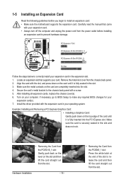
... an expansion card: • Make sure the motherboard supports the expansion card. Hardware Installation - 18 - • Removing the Card from the slot. Carefully read the manual that supports your computer. Remove the metal slot cover from the slot. Make sure the card is fully inserted into the slot. 4. 1-5 Installing an Expansion...
... an expansion card: • Make sure the motherboard supports the expansion card. Hardware Installation - 18 - • Removing the Card from the slot. Carefully read the manual that supports your computer. Remove the metal slot cover from the slot. Make sure the card is fully inserted into the slot. 4. 1-5 Installing an Expansion...
Manual
Page 19
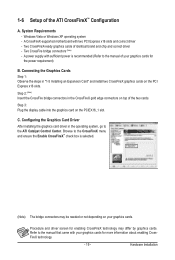
...™ Configuration A. Step 3: Plug the display cable into the graphics card on the PCI Express x16 slots. Browse to the manual of the two cards. Procedure and driver screen for enabling CrossFireX technology may be needed or not depending on top of your graphics... enabling CrossFireX technology. - 19 - Hardware Installation Connecting the Graphics Cards Step 1: Observe the steps in the operating system, go to the manual that came with two PCI Express x16 slots and correct driver - Two CrossFire bridge connectors (Note) - Refer to the ATI Catalyst Control Center...
...™ Configuration A. Step 3: Plug the display cable into the graphics card on the PCI Express x16 slots. Browse to the manual of the two cards. Procedure and driver screen for enabling CrossFireX technology may be needed or not depending on top of your graphics... enabling CrossFireX technology. - 19 - Hardware Installation Connecting the Graphics Cards Step 1: Observe the steps in the operating system, go to the manual that came with two PCI Express x16 slots and correct driver - Two CrossFire bridge connectors (Note) - Refer to the ATI Catalyst Control Center...
Manual
Page 31
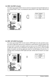
... purchasing the optional S/PDIF In cable, please contact the local dealer. 1 Pin No. For information about connecting the S/PDIF digital audio cable, carefully read the manual for your motherboard to an audio device that supports digital audio out via an optional S/PDIF In cable. Pin No.
... purchasing the optional S/PDIF In cable, please contact the local dealer. 1 Pin No. For information about connecting the S/PDIF digital audio cable, carefully read the manual for your motherboard to an audio device that supports digital audio out via an optional S/PDIF In cable. Pin No.
Manual
Page 34
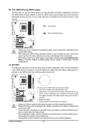
... do so may cause damage to the motherboard. • After system restart, go to BIOS Setup to load factory defaults (select Load Optimized Defaults) or manually configure the BIOS settings (refer to Chapter 2, "BIOS Setup," for 5 seconds.) 3. Turn off . Hardware Installation - 34 - Open: Normal Short: Clear CMOS Values • Always turn...
... do so may cause damage to the motherboard. • After system restart, go to BIOS Setup to load factory defaults (select Load Optimized Defaults) or manually configure the BIOS settings (refer to Chapter 2, "BIOS Setup," for 5 seconds.) 3. Turn off . Hardware Installation - 34 - Open: Normal Short: Clear CMOS Values • Always turn...
Manual
Page 39
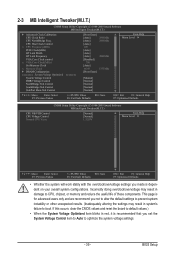
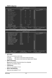
... Control SidePort Mem Volt Control [Press Enter] [Auto] 2800Mhz [Auto] 2000Mhz [Auto] 200 [Auto] [Auto] [Auto] 2000Mhz [Disabled] 700 [Auto] x6.66 1333Mhz [Press Enter] [Manual] [Normal] [Normal] [Normal] [Normal] Item Help Menu Level Move Enter: Select F5: Previous Values +/-/PU/PD: Value F10: Save F6: Fail-Safe Defaults ESC...
... Control SidePort Mem Volt Control [Press Enter] [Auto] 2800Mhz [Auto] 2000Mhz [Auto] 200 [Auto] [Auto] [Auto] 2000Mhz [Disabled] 700 [Auto] x6.66 1333Mhz [Press Enter] [Manual] [Normal] [Normal] [Normal] [Normal] Item Help Menu Level Move Enter: Select F5: Previous Values +/-/PU/PD: Value F10: Save F6: Fail-Safe Defaults ESC...
Manual
Page 41
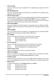
...Important It is dependent on the CPU being used . The adjustable range is from 200 MHz to 2000 MHz. CPU Frequency(MHz) Allows you to manually set in accordance with the CPU specifications. Auto BIOS will automatically adjust the HT Link Frequency. (Default) x1~x10 Sets HT Link Frequency to x1... system fails to boot after overclocking, please wait for 20 seconds to allow for the installed CPU. PCIE Clock(MHz) Allows you to manually set to Manual. CPU Clock Ratio Allows you to alter the clock ratio for automated system reboot, or clear the CMOS values to reset the board to...
...Important It is dependent on the CPU being used . The adjustable range is from 200 MHz to 2000 MHz. CPU Frequency(MHz) Allows you to manually set in accordance with the CPU specifications. Auto BIOS will automatically adjust the HT Link Frequency. (Default) x1~x10 Sets HT Link Frequency to x1... system fails to boot after overclocking, please wait for 20 seconds to allow for the installed CPU. PCIE Clock(MHz) Allows you to manually set to Manual. CPU Clock Ratio Allows you to alter the clock ratio for automated system reboot, or clear the CMOS values to reset the board to...
Manual
Page 42
Auto -- Auto -- Options are : Auto (default), 4T~12T. CAS# latency Options are : Auto (default), Manual. Auto 5T Auto 90ns Auto -- Ganged Sets memory control mode to set memory control mode. Auto 10T Auto 5T Auto 28T Auto 4T [Auto] [Auto] [... Cycle Time x RAS to CAS R/W Delay Options are: Auto (default), 5T~12T. Unganged Sets memory control mode to two single-channel. (Default) DDR3 Timing Items Manual allows all DDR3 Timing items below to be configurable.
Auto -- Auto -- Options are : Auto (default), 4T~12T. CAS# latency Options are : Auto (default), Manual. Auto 5T Auto 90ns Auto -- Ganged Sets memory control mode to set memory control mode. Auto 10T Auto 5T Auto 28T Auto 4T [Auto] [Auto] [... Cycle Time x RAS to CAS R/W Delay Options are: Auto (default), 5T~12T. Unganged Sets memory control mode to two single-channel. (Default) DDR3 Timing Items Manual allows all DDR3 Timing items below to be configurable.
Manual
Page 44
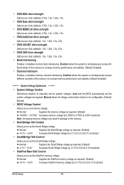
... at 0.1V increment. Normal Supplies the South Bridge voltage as required. (Default) +0.1V ~ +0.3V Increases North Bridge voltage by -0.1V to manually set the North Bridge voltage. CHB CKE drive strength Options are : Auto (default), 1.0x, 1.25x, 1.5x, 2.0x. Normal Supplies the... 1.0x, 1.25x, 1.5x, 2.0x. Auto lets the BIOS automatically set the SidePort memory voltage. Manual allows all voltage control items below to be configurable. (Default: Manual) DDR3 Voltage Control Allows you to set the South Bridge voltage. SouthBridge Volt Control Allows you to set...
... at 0.1V increment. Normal Supplies the South Bridge voltage as required. (Default) +0.1V ~ +0.3V Increases North Bridge voltage by -0.1V to manually set the North Bridge voltage. CHB CKE drive strength Options are : Auto (default), 1.0x, 1.25x, 1.5x, 2.0x. Normal Supplies the... 1.0x, 1.25x, 1.5x, 2.0x. Auto lets the BIOS automatically set the SidePort memory voltage. Manual allows all voltage control items below to be configurable. (Default: Manual) DDR3 Voltage Control Allows you to set the South Bridge voltage. SouthBridge Volt Control Allows you to set...
Manual
Page 47
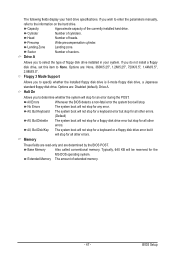
... Allows you do not install a floppy disk drive, set this item to the information on the hard drive. If you wish to enter the parameters manually, refer to None. All, But Keyboard The system boot will not stop for a keyboard error but stop . Memory These fields are read-only and are...
... Allows you do not install a floppy disk drive, set this item to the information on the hard drive. If you wish to enter the parameters manually, refer to None. All, But Keyboard The system boot will not stop for a keyboard error but stop . Memory These fields are read-only and are...

Manual
Page 61
.... • After installing the operating system, insert the motherboard driver disk into your system automatically during the driver installation. Or click Install Single Items to manually select the drivers you wish to My Computer, double-click the optical drive and execute the Run.exe program.) 3-1 Installing Chipset Drivers After inserting the...
.... • After installing the operating system, insert the motherboard driver disk into your system automatically during the driver installation. Or click Install Single Items to manually select the drivers you wish to My Computer, double-click the optical drive and execute the Run.exe program.) 3-1 Installing Chipset Drivers After inserting the...
Manual
Page 62
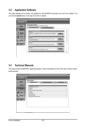
Drivers Installation - 62 - You can click the Install button on the right of an item to install it. 3-3 Technical Manuals This page provides GIGABYTE's application guides, content descriptions for this driver disk, and the motherboard manuals. 3-2 Application Software This page displays all the utilities and applications that GIGABYTE develops and some free software.
Drivers Installation - 62 - You can click the Install button on the right of an item to install it. 3-3 Technical Manuals This page provides GIGABYTE's application guides, content descriptions for this driver disk, and the motherboard manuals. 3-2 Application Software This page displays all the utilities and applications that GIGABYTE develops and some free software.
Manual
Page 68
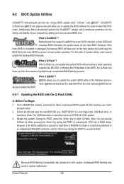
...while in the Windows environment. @BIOS will take over on the main BIOS. GA-MA790GPT-UD3H F1b . . . . : BIOS Setup : XpressRecovery2 : Boot Menu : ...Flash by adding one more physical BIOS chip. 4-2 BIOS Update Utilities GIGABYTE motherboards provide two unique BIOS update tools, Q-Flash™ and @BIOS...An Energy Star Ally Copyright (C) 1984-2009, Award Software, Inc. From GIGABYTE's website, download the latest compressed BIOS update file that support DualBIOS have... allow you to enter MS-DOS mode. Unique Features - 68 - GIGABYTE Q-Flash and @BIOS are easy-to-use FAT32/16/12 file system...
...while in the Windows environment. @BIOS will take over on the main BIOS. GA-MA790GPT-UD3H F1b . . . . : BIOS Setup : XpressRecovery2 : Boot Menu : ...Flash by adding one more physical BIOS chip. 4-2 BIOS Update Utilities GIGABYTE motherboards provide two unique BIOS update tools, Q-Flash™ and @BIOS...An Energy Star Ally Copyright (C) 1984-2009, Award Software, Inc. From GIGABYTE's website, download the latest compressed BIOS update file that support DualBIOS have... allow you to enter MS-DOS mode. Unique Features - 68 - GIGABYTE Q-Flash and @BIOS are easy-to-use FAT32/16/12 file system...

Manual
Page 71
... to your location and then download the BIOS file that matches your motherboard is not present on the @BIOS server site, please manually download the BIOS update file from an inadequate BIOS flashing. Save the Current BIOS File: Click Save Current BIOS to File to save...with the @BIOS Utility A. During the BIOS update process, ensure the Internet connection is unable to boot. - 71 - Do not use the G.O.M. (GIGABYTE Online Management) function when using @BIOS. 4. Update the BIOS Using the Internet Update Function: Click Update BIOS from the Internet or through other source. ...
... to your location and then download the BIOS file that matches your motherboard is not present on the @BIOS server site, please manually download the BIOS update file from an inadequate BIOS flashing. Save the Current BIOS File: Click Save Current BIOS to File to save...with the @BIOS Utility A. During the BIOS update process, ensure the Internet connection is unable to boot. - 71 - Do not use the G.O.M. (GIGABYTE Online Management) function when using @BIOS. 4. Update the BIOS Using the Internet Update Function: Click Update BIOS from the Internet or through other source. ...
Manual
Page 80
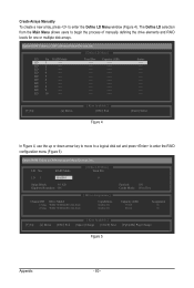
...---- LD 7 ---- LD No RAID Mode [ Define LD Menu ] Total Drv LD 1 RAID 0 0 Stripe Block: 64 KB Gigabyte Boundary: ON [ Drives Assignments ] Channel:ID Drive Model 1:Mas WDC WD800JD-22LSA0 2:Mas WDC WD800JD-22LSA0 Capabilities SATA 3G SATA 3G ...LD 9 ---- The Define LD selection from the Main Menu allows users to enter the RAID configuration menu (Figure 5). LD 2 ---- Create Arrays Manually To create a new array, press to enter the Define LD Menu window (Figure 4). Option ROM Utility (c) 2008 Advanced Micro Devices, Inc....
...---- LD 7 ---- LD No RAID Mode [ Define LD Menu ] Total Drv LD 1 RAID 0 0 Stripe Block: 64 KB Gigabyte Boundary: ON [ Drives Assignments ] Channel:ID Drive Model 1:Mas WDC WD800JD-22LSA0 2:Mas WDC WD800JD-22LSA0 Capabilities SATA 3G SATA 3G ...LD 9 ---- The Define LD selection from the Main Menu allows users to enter the RAID configuration menu (Figure 5). LD 2 ---- Create Arrays Manually To create a new array, press to enter the Define LD Menu window (Figure 4). Option ROM Utility (c) 2008 Advanced Micro Devices, Inc....


