Manual
Page 1
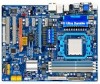
GA-MA790GPT-UD3H AM3 socket motherboard for AMD Phenom™ II processor/AMD Athlon™ II processor User's Manual Rev. 1002 12ME-MA79PT3-1002R
GA-MA790GPT-UD3H AM3 socket motherboard for AMD Phenom™ II processor/AMD Athlon™ II processor User's Manual Rev. 1002 12ME-MA79PT3-1002R
Manual
Page 3
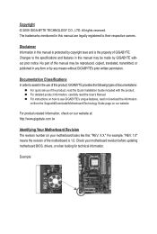
... legally registered to the specifications and features in the use GIGABYTE's unique features, read or download the information on/from the Support&Downloads\Motherboard\Technology Guide page on your motherboard revision before updating motherboard BIOS, drivers, or when looking for technical information. Check your motherboard looks like this manual is protected by copyright laws and...
... legally registered to the specifications and features in the use GIGABYTE's unique features, read or download the information on/from the Support&Downloads\Motherboard\Technology Guide page on your motherboard revision before updating motherboard BIOS, drivers, or when looking for technical information. Check your motherboard looks like this manual is protected by copyright laws and...
Manual
Page 4
Table of Contents Box Contents...6 Optional Items...6 GA-MA790GPT-UD3H Motherboard Layout 7 Block Diagram...8 Chapter 1 Hardware Installation 9 1-1 Installation Precautions 9 1-2 Product Specifications 10 1-3 Installing the CPU and CPU Cooler 13 1-3-1 Installing the CPU 13 1-3-2 Installing the CPU ...
Table of Contents Box Contents...6 Optional Items...6 GA-MA790GPT-UD3H Motherboard Layout 7 Block Diagram...8 Chapter 1 Hardware Installation 9 1-1 Installation Precautions 9 1-2 Product Specifications 10 1-3 Installing the CPU and CPU Cooler 13 1-3-1 Installing the CPU 13 1-3-2 Installing the CPU ...
Manual
Page 6
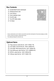
...-1IE008-0*R) 2-port SATA power cable (Part No. 12CF1-2SERPW-0*R) S/PDIF In cable (Part No. 12CR1-1SPDIN-0*R) COM port cable (Part No. 12CF1-1CM001-3*R) - 6 - Box Contents GA-MA790GPT-UD3H motherboard Motherboard driver disk User's Manual Quick Installation Guide One IDE cable Two SATA 3Gb/s cables I/O Shield • The box contents above are subject to change without...
...-1IE008-0*R) 2-port SATA power cable (Part No. 12CF1-2SERPW-0*R) S/PDIF In cable (Part No. 12CR1-1SPDIN-0*R) COM port cable (Part No. 12CF1-1CM001-3*R) - 6 - Box Contents GA-MA790GPT-UD3H motherboard Motherboard driver disk User's Manual Quick Installation Guide One IDE cable Two SATA 3Gb/s cables I/O Shield • The box contents above are subject to change without...
Manual
Page 7
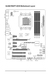
GA-MA790GPT-UD3H Motherboard Layout KB_USB CPU_FAN ATX VGA_DVI ATX_12V_2X4 Socket AM3 HDMI OPTICAL USB_1394 USB_LAN PWR_FAN F_USB1 F_USB2 F_USB3 DDR3_1 DDR3_2 DDR3_3 DDR3_4 AUDIO SidePort F_AUDIO PCIEX1_1 AMD 790GX Meory IDE NB_FAN RTL8111C PCIEX16_1 CD_IN PCIEX1_2 PCIEX1_3 GA-MA790GPT-UD3H AMD SB750 BATTERY CLR_CMOS M_BIOS B_BIOS CODEC SPDIF_OUT PCIEX8_1 SPDIF_IN PCI1 TSB43AB23 SYS_FAN1 SATA2_4 SATA2_5 SATA2_2 SATA2_3 IT8718 PCI2 SATA2_0 SATA2_1 SYS_FAN2 COM CI F_PANEL FDD F_1394_1 F_1394_2 PWR_LED - 7 -
GA-MA790GPT-UD3H Motherboard Layout KB_USB CPU_FAN ATX VGA_DVI ATX_12V_2X4 Socket AM3 HDMI OPTICAL USB_1394 USB_LAN PWR_FAN F_USB1 F_USB2 F_USB3 DDR3_1 DDR3_2 DDR3_3 DDR3_4 AUDIO SidePort F_AUDIO PCIEX1_1 AMD 790GX Meory IDE NB_FAN RTL8111C PCIEX16_1 CD_IN PCIEX1_2 PCIEX1_3 GA-MA790GPT-UD3H AMD SB750 BATTERY CLR_CMOS M_BIOS B_BIOS CODEC SPDIF_OUT PCIEX8_1 SPDIF_IN PCI1 TSB43AB23 SYS_FAN1 SATA2_4 SATA2_5 SATA2_2 SATA2_3 IT8718 PCI2 SATA2_0 SATA2_1 SYS_FAN2 COM CI F_PANEL FDD F_1394_1 F_1394_2 PWR_LED - 7 -
Manual
Page 9
...computer system in a high-temperature environment. • Turning on the computer power during the installation process can become damaged as a motherboard, CPU or memory. Prior to installation, carefully read the user's manual and follow these procedures: • Prior to installation,... as a result of the product, please consult a certified computer technician. - 9 - Chapter 1 Hardware Installation 1-1 Installation Precautions The motherboard contains numerous delicate electronic circuits and components which can lead to damage to system components as well as physical harm to the user. ...
...computer system in a high-temperature environment. • Turning on the computer power during the installation process can become damaged as a motherboard, CPU or memory. Prior to installation, carefully read the user's manual and follow these procedures: • Prior to installation,... as a result of the product, please consult a certified computer technician. - 9 - Chapter 1 Hardware Installation 1-1 Installation Precautions The motherboard contains numerous delicate electronic circuits and components which can lead to damage to system components as well as physical harm to the user. ...

Manual
Page 12
... 5) Whether the CPU/system fan speed control function is supported will be less than 4 GB. (Note 2) The DVI-D port does not support D-Sub connection by motherboard model. The PCIEX8_1 slot shares bandwidth with a PCI Express graphics card, the PCIEX16_1 slot will operate at up to install it in the PCIEX16_1 slot.
... 5) Whether the CPU/system fan speed control function is supported will be less than 4 GB. (Note 2) The DVI-D port does not support D-Sub connection by motherboard model. The PCIEX8_1 slot shares bandwidth with a PCI Express graphics card, the PCIEX16_1 slot will operate at up to install it in the PCIEX16_1 slot.
Manual
Page 13
... socket.) • Apply an even and thin layer of thermal grease on the computer if the CPU cooler is not recommended that the motherboard supports the CPU. (Go to GIGABYTE's website for the peripherals. The CPU cannot be set beyond the standard specifications, please do so according to prevent hardware damage. •...
... socket.) • Apply an even and thin layer of thermal grease on the computer if the CPU cooler is not recommended that the motherboard supports the CPU. (Go to GIGABYTE's website for the peripherals. The CPU cannot be set beyond the standard specifications, please do so according to prevent hardware damage. •...
Manual
Page 14
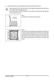
... Installation - 14 - Make sure that the CPU pins fit perfectly into the CPU socket. Follow the steps below to correctly install the CPU into the motherboard CPU socket. • Before installing the CPU, make sure to turn off the computer and unplug the power cord from the power outlet to prevent...
... Installation - 14 - Make sure that the CPU pins fit perfectly into the CPU socket. Follow the steps below to correctly install the CPU into the motherboard CPU socket. • Before installing the CPU, make sure to turn off the computer and unplug the power cord from the power outlet to prevent...
Manual
Page 15
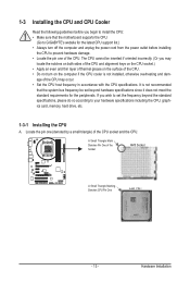
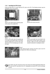
1-3-2 Installing the CPU Cooler Follow the steps below to correctly install the CPU cooler on the CPU. (The following procedure uses the GIGABYTE cooler as the picture above shows) to lock into place. (Refer to the CPU. On the other side,push straight down on the the CPU ....) Step 1: Apply an even and thin layer of thermal grease on the surface of the CPU cooler to the CPU fan header (CPU_FAN) on the motherboard. Inadequately removing the CPU cooler may adhere to your CPU cooler installation manual for instructions on the CPU. Step 3: Hook the CPU cooler clip to...
1-3-2 Installing the CPU Cooler Follow the steps below to correctly install the CPU cooler on the CPU. (The following procedure uses the GIGABYTE cooler as the picture above shows) to lock into place. (Refer to the CPU. On the other side,push straight down on the the CPU ....) Step 1: Apply an even and thin layer of thermal grease on the surface of the CPU cooler to the CPU fan header (CPU_FAN) on the motherboard. Inadequately removing the CPU cooler may adhere to your CPU cooler installation manual for instructions on the CPU. Step 3: Hook the CPU cooler clip to...
Manual
Page 16
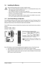
... mode will automatically detect the specifications and capacity of the same capacity, brand, speed, and chips be used . (Go to GIGABYTE's website for optimum performance. After the memory is installed, the BIOS will double the original memory bandwidth. DS/SS DS/SS Four...=Double-Sided, "- -"=No Memory) If two memory modules are to insert the memory, switch the direction. 1-4-1 Dual Channel Memory Configuration This motherboard provides four DDR3 memory sockets and supports Dual Channel Technology. When enabling Dual Channel mode with two or four memory modules, it is installed....
... mode will automatically detect the specifications and capacity of the same capacity, brand, speed, and chips be used . (Go to GIGABYTE's website for optimum performance. After the memory is installed, the BIOS will double the original memory bandwidth. DS/SS DS/SS Four...=Double-Sided, "- -"=No Memory) If two memory modules are to insert the memory, switch the direction. 1-4-1 Dual Channel Memory Configuration This motherboard provides four DDR3 memory sockets and supports Dual Channel Technology. When enabling Dual Channel mode with two or four memory modules, it is installed....
Manual
Page 17
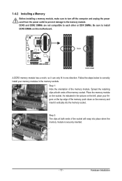
..., make sure to turn off the computer and unplug the power cord from the power outlet to prevent damage to install DDR3 DIMMs on this motherboard.
..., make sure to turn off the computer and unplug the power cord from the power outlet to prevent damage to install DDR3 DIMMs on this motherboard.
Manual
Page 18
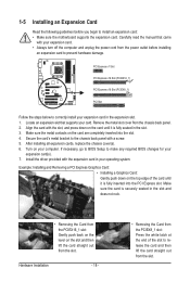
... the slot and then lift the card straight out from the power outlet before you begin to install an expansion card: • Make sure the motherboard supports the expansion card. Hardware Installation - 18 - • Removing the Card from the PCIEX8_1 slot: Press the white latch at the end of the card...
... the slot and then lift the card straight out from the power outlet before you begin to install an expansion card: • Make sure the motherboard supports the expansion card. Hardware Installation - 18 - • Removing the Card from the PCIEX8_1 slot: Press the white latch at the end of the card...
Manual
Page 19
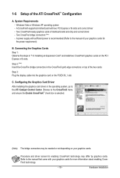
... driver - Two CrossFire bridge connectors (Note) - Step 3: Plug the display cable into the graphics card on the PCI Express x16 slots. System Requirements - A CrossFireX-supported motherboard with sufficient power is recommended (Refer to the CrossFireX menu and ensure the Enable CrossFireX™ check box is selected. (Note) The bridge connectors may...
... driver - Two CrossFire bridge connectors (Note) - Step 3: Plug the display cable into the graphics card on the PCI Express x16 slots. System Requirements - A CrossFireX-supported motherboard with sufficient power is recommended (Refer to the CrossFireX menu and ensure the Enable CrossFireX™ check box is selected. (Note) The bridge connectors may...

Manual
Page 20
...with a discrete graphics card, ATI Hybrid CrossFireX can provide significantly advanced display performance for AMD platform. An ATI Hybrid CrossFireX-supported motherboard and correct driver - Connecting the Graphics Cards Step 1: Observe the steps in "1-5 Installing an Expansion Card" and install an ...ATI Hybrid CrossFireX-supported graphics card on configuring an ATI Hybrid CrossFireX system. Configuring the Graphics Driver After installing the motherboard driver in BIOS Setup, be sure to set the following items under the Advanced BIOS Features menu: - Windows Vista or ...
...with a discrete graphics card, ATI Hybrid CrossFireX can provide significantly advanced display performance for AMD platform. An ATI Hybrid CrossFireX-supported motherboard and correct driver - Connecting the Graphics Cards Step 1: Observe the steps in "1-5 Installing an Expansion Card" and install an ...ATI Hybrid CrossFireX-supported graphics card on configuring an ATI Hybrid CrossFireX system. Configuring the Graphics Driver After installing the motherboard driver in BIOS Setup, be sure to set the following items under the Advanced BIOS Features menu: - Windows Vista or ...

Manual
Page 22
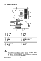
... 1394a Port The IEEE 1394 port supports the IEEE 1394a specification, featuring high speed, high bandwidth and hotplug capabilities. Dual Display Configurations: This motherboard provides three ports for an IEEE 1394a device. Dual Display Combination DVI-D + D-Sub DVI-D + HDMI HDMI + D-Sub Supported or Not... Acceleration is occurring • When removing the cable connected to an external audio system that your device and then remove it from the motherboard. • When removing the cable, pull it side to side to 1 Gbps data rate. Use this feature, ensure that supports...
... 1394a Port The IEEE 1394 port supports the IEEE 1394a specification, featuring high speed, high bandwidth and hotplug capabilities. Dual Display Configurations: This motherboard provides three ports for an IEEE 1394a device. Dual Display Combination DVI-D + D-Sub DVI-D + HDMI HDMI + D-Sub Supported or Not... Acceleration is occurring • When removing the cable connected to an external audio system that your device and then remove it from the motherboard. • When removing the cable, pull it side to side to 1 Gbps data rate. Use this feature, ensure that supports...
Manual
Page 24
..., make sure your devices are compliant with the connectors you wish to connect. • Before installing the devices, be sure to the connector on the motherboard.
..., make sure your devices are compliant with the connectors you wish to connect. • Before installing the devices, be sure to the connector on the motherboard.
Manual
Page 25
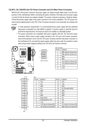
... connector is not connected, the computer will not start. • To meet expansion requirements, it is turned off and all the components on the motherboard. When using a power supply providing a 2x2 12V and a 2x10 power connector. 8 4 5 1 ATX_12V_2X4 ATX_12V_2X4: Pin No. Do not insert... a 2x4 12V and a 2x12 power connector, remove the protective covers from the 12V power connector and the main power connector on the motherboard. The 12V power connector mainly supplies power to an unstable or unbootable system. • The power connectors are properly installed. 1/2) ATX_12V_2X4/...
... connector is not connected, the computer will not start. • To meet expansion requirements, it is turned off and all the components on the motherboard. When using a power supply providing a 2x2 12V and a 2x10 power connector. 8 4 5 1 ATX_12V_2X4 ATX_12V_2X4: Pin No. Do not insert... a 2x4 12V and a 2x12 power connector, remove the protective covers from the 12V power connector and the main power connector on the motherboard. The 12V power connector mainly supplies power to an unstable or unbootable system. • The power connectors are properly installed. 1/2) ATX_12V_2X4/...
Manual
Page 26
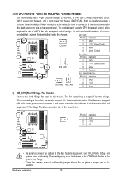
When connecting a fan cable, be installed inside the chassis. The motherboard supports CPU fan speed control, which requires the use of a CPU fan with color-coded power connector wires. Most fans are not configuration jumper ... fan cable to prevent your CPU, North Bridge and system from overheating. The black connector wire is recom- 3/4/5) CPU_FAN/SYS_FAN1/SYS_FAN2/PWR_FAN (Fan Headers) The motherboard has a 4-pin CPU fan header (CPU_FAN), a 3-pin (SYS_FAN2) and a 4-pin (SYS_ FAN1) system fan headers, and a 3-pin power fan header (PWR_FAN). A red power connector...
When connecting a fan cable, be installed inside the chassis. The motherboard supports CPU fan speed control, which requires the use of a CPU fan with color-coded power connector wires. Most fans are not configuration jumper ... fan cable to prevent your CPU, North Bridge and system from overheating. The black connector wire is recom- 3/4/5) CPU_FAN/SYS_FAN1/SYS_FAN2/PWR_FAN (Fan Headers) The motherboard has a 4-pin CPU fan header (CPU_FAN), a 3-pin (SYS_FAN2) and a 4-pin (SYS_ FAN1) system fan headers, and a 3-pin power fan header (PWR_FAN). A red power connector...
Manual
Page 30
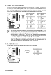
...(L) 10 GND 10 NC • The front panel audio header supports HD audio by default. Incorrect connection between the module connector and the motherboard header will be present on each wire instead of a single plug. If your chassis provides an AC'97 front panel audio module, refer to... Audio: For AC'97 Front Panel Audio: Pin No. Pin No. You may connect the audio cable that has separated connectors on both of the motherboard header. Definition 1 CD-L 1 2 GND 3 GND 4 CD-R Hardware Installation - 30 - 12) F_AUDIO (Front Panel Audio Header) The front panel audio header ...
...(L) 10 GND 10 NC • The front panel audio header supports HD audio by default. Incorrect connection between the module connector and the motherboard header will be present on each wire instead of a single plug. If your chassis provides an AC'97 front panel audio module, refer to... Audio: For AC'97 Front Panel Audio: Pin No. Pin No. You may connect the audio cable that has separated connectors on both of the motherboard header. Definition 1 CD-L 1 2 GND 3 GND 4 CD-R Hardware Installation - 30 - 12) F_AUDIO (Front Panel Audio Header) The front panel audio header ...


