Manual
Page 1
GA-M720-ES3 AM2+/AM2 socket motherboard for AMD PhenomTM II processor/AMD PhenomTM processor/ AMD AthlonTM II processor/AMD AthlonTM processor/ AMD SempronTM processor User's Manual Rev. 1001 12ME-M720ES3-1001R
GA-M720-ES3 AM2+/AM2 socket motherboard for AMD PhenomTM II processor/AMD PhenomTM processor/ AMD AthlonTM II processor/AMD AthlonTM processor/ AMD SempronTM processor User's Manual Rev. 1001 12ME-M720ES3-1001R

Manual
Page 2
Motherboard GA-M720-ES3 June 25, 2009 Motherboard GA-M720-ES3 June 25, 2009
Motherboard GA-M720-ES3 June 25, 2009 Motherboard GA-M720-ES3 June 25, 2009

Manual
Page 3
...notice. Example: Changes to their respective owners. For product-related information, check on our website at: http://www.gigabyte.com.tw Identifying Your Motherboard Revision The revision number on our website. The trademarks mentioned in this manual may be reproduced, copied, translated, ...transmitted, or published in any form or by GIGABYTE without GIGABYTE's prior written permission. No part of the motherboard is the property of the product, read the Quick Installation Guide included with the product. ...
...notice. Example: Changes to their respective owners. For product-related information, check on our website at: http://www.gigabyte.com.tw Identifying Your Motherboard Revision The revision number on our website. The trademarks mentioned in this manual may be reproduced, copied, translated, ...transmitted, or published in any form or by GIGABYTE without GIGABYTE's prior written permission. No part of the motherboard is the property of the product, read the Quick Installation Guide included with the product. ...
Manual
Page 4
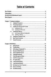
Table of Contents Box Contents ...6 OptionalItems...6 GA-M720-ES3 Motherboard Layout 7 Block Diagram...8 Chapter 1 Hardware Installation 9 1-1 Installation Precautions 9 1-2 Product Specifications 10 1-3 Installing the CPU and CPU Cooler 12 1-3-1 Installing the CPU 12 1-3-2 Installing the CPU ...
Table of Contents Box Contents ...6 OptionalItems...6 GA-M720-ES3 Motherboard Layout 7 Block Diagram...8 Chapter 1 Hardware Installation 9 1-1 Installation Precautions 9 1-2 Product Specifications 10 1-3 Installing the CPU and CPU Cooler 12 1-3-1 Installing the CPU 12 1-3-2 Installing the CPU ...

Manual
Page 6
Box Contents GA-M720-ES3 motherboard Motherboard driver disk User's Manual Quick Installation Guide One IDE cable Two SATA 3Gb/s cables I/O Shield • The box contents above are subject to change without notice. • The motherboard image is for reference only and the actual items shall depend on product package you obtain. Optional Items Floppy disk drive...
Box Contents GA-M720-ES3 motherboard Motherboard driver disk User's Manual Quick Installation Guide One IDE cable Two SATA 3Gb/s cables I/O Shield • The box contents above are subject to change without notice. • The motherboard image is for reference only and the actual items shall depend on product package you obtain. Optional Items Floppy disk drive...

Manual
Page 7
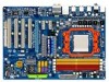
GA-M720-ES3 Motherboard Layout KB_MS RCA_SPDIF R_USB R_USB R_USB USB_LAN ATX_12V Socket AM2 PWR_FAN F_AUDIO AUDIO CPU_FAN PCIEX1_1 RTL8111C PCIEX1_2 PCIEX16 CODEC PCI1 PCI2 NVIDIA® nForce 720D GA-M720-ES3 SATA2_2 SATA2_1 SATA2_0 SATA2_5 SATA2_4 SATA2_3 BATTERY DDR2_1 DDR2_2 DDR2_3 DDR2_4 ATX IDE CD_IN SPDIF_O SYS_FAN1 PCI3 IT8720 PCI4 M_BIOS B_BIOS COM FDD TSB43AB23 SYS_FAN2 CI F_PANEL F_USB1 PWR_LED F_USB2 CLR_CMOS - 7 -
GA-M720-ES3 Motherboard Layout KB_MS RCA_SPDIF R_USB R_USB R_USB USB_LAN ATX_12V Socket AM2 PWR_FAN F_AUDIO AUDIO CPU_FAN PCIEX1_1 RTL8111C PCIEX1_2 PCIEX16 CODEC PCI1 PCI2 NVIDIA® nForce 720D GA-M720-ES3 SATA2_2 SATA2_1 SATA2_0 SATA2_5 SATA2_4 SATA2_3 BATTERY DDR2_1 DDR2_2 DDR2_3 DDR2_4 ATX IDE CD_IN SPDIF_O SYS_FAN1 PCI3 IT8720 PCI4 M_BIOS B_BIOS COM FDD TSB43AB23 SYS_FAN2 CI F_PANEL F_USB1 PWR_LED F_USB2 CLR_CMOS - 7 -

Manual
Page 9
... to wear an electrostatic discharge (ESD) wrist strap when handling electronic components such as a motherboard, CPU or memory. Chapter 1 Hardware Installation 1-1 Installation Precautions The motherboard contains numerous delicate electronic circuits and components which can lead to damage to system components as well...the AC power by your hands dry and first touch a metal object to eliminate static electricity. • Prior to installing the motherboard, please have an ESD wrist strap, keep your dealer. Prior to installation, carefully read the user's manual and follow these procedures...
... to wear an electrostatic discharge (ESD) wrist strap when handling electronic components such as a motherboard, CPU or memory. Chapter 1 Hardware Installation 1-1 Installation Precautions The motherboard contains numerous delicate electronic circuits and components which can lead to damage to system components as well...the AC power by your hands dry and first touch a metal object to eliminate static electricity. • Prior to installing the motherboard, please have an ESD wrist strap, keep your dealer. Prior to installation, carefully read the user's manual and follow these procedures...
Manual
Page 10
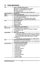
...II processor/AMD PhenomTM processor/ AMD AthlonTM II processor/AMD AthlonTM processor/ AMD SempronTM processor (Go to GIGABYTE's website for the latest CPU support list.) 5200/2000 MT/s NVIDIA® nForce 720D chipset 4...Note 1) Dual channel memory architecture Support for DDR2 1200 (Note 2)/1066/800 MHz memory modules (Go to GIGABYTE's website for the latest memory support list.) Realtek ALC888 codec High Definition Audio 2/4/5.1/7.1-channel Support for S/PDIF...header 1 x front panel header 1 x front panel audio header 1 x CD In connector 1 x S/PDIF Out header GA-M720-ES3 Motherboard - 10 -
...II processor/AMD PhenomTM processor/ AMD AthlonTM II processor/AMD AthlonTM processor/ AMD SempronTM processor (Go to GIGABYTE's website for the latest CPU support list.) 5200/2000 MT/s NVIDIA® nForce 720D chipset 4...Note 1) Dual channel memory architecture Support for DDR2 1200 (Note 2)/1066/800 MHz memory modules (Go to GIGABYTE's website for the latest memory support list.) Realtek ALC888 codec High Definition Audio 2/4/5.1/7.1-channel Support for S/PDIF...header 1 x front panel header 1 x front panel audio header 1 x CD In connector 1 x S/PDIF Out header GA-M720-ES3 Motherboard - 10 -

Manual
Page 11
... CPU/System fan speed control function is supported will depend on the CPU/ System cooler you install. (Note 4) Available functions in EasyTune may differ by motherboard model. (Note 5) Due to the hardware limitation, you must install the AMD AM3/ AM2+ Series CPU toenable support for Easy Energy Saver. - 11 - Hardware Installation...
... CPU/System fan speed control function is supported will depend on the CPU/ System cooler you install. (Note 4) Available functions in EasyTune may differ by motherboard model. (Note 5) Due to the hardware limitation, you must install the AMD AM3/ AM2+ Series CPU toenable support for Easy Energy Saver. - 11 - Hardware Installation...
Manual
Page 12
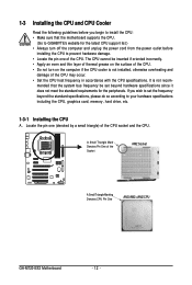
mended that the motherboard supports the CPU. (Go to GIGABYTE's website for the peripherals. A Small Triangle Mark Denotes Pin One of the Socket AM2 Socket A Small Triangle Marking Denotes CPU Pin One AM3/AM2+/AM2 CPU GA-M720-ES3 Motherboard - 12 - If you begin to install the CPU: • Make sure that the system bus frequency be...
mended that the motherboard supports the CPU. (Go to GIGABYTE's website for the peripherals. A Small Triangle Mark Denotes Pin One of the Socket AM2 Socket A Small Triangle Marking Denotes CPU Pin One AM3/AM2+/AM2 CPU GA-M720-ES3 Motherboard - 12 - If you begin to install the CPU: • Make sure that the system bus frequency be...

Manual
Page 13
... sure to turn off the computer and unplug the power cord from the power outlet to prevent damage to correctly install the CPU into the motherboard CPU socket. B. Make sure that the CPU pins fit perfectly into the fully locked position. The CPU cannot fit in if oriented incorrectly...
... sure to turn off the computer and unplug the power cord from the power outlet to prevent damage to correctly install the CPU into the motherboard CPU socket. B. Make sure that the CPU pins fit perfectly into the fully locked position. The CPU cannot fit in if oriented incorrectly...
Manual
Page 14
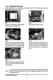
1-3-2 Installing the CPU Cooler Follow the steps below to correctly install the CPU cooler on the CPU. (The following procedure uses the GIGABYTE cooler as the picture above shows) to lock into place. (Refer to your CPU cooler installation manual for instructions on installing the cooler.) Step 5: Finally,... the mounting lug on the CPU. On the other side, push straight down on the the CPU cooler clip to hook it to the CPU. GA-M720-ES3 Motherboard - 14 - Step 3: Hook the CPU cooler clip to the CPU fan header (CPU_FAN) on the retention frame. Use extreme care when removing the CPU ...
1-3-2 Installing the CPU Cooler Follow the steps below to correctly install the CPU cooler on the CPU. (The following procedure uses the GIGABYTE cooler as the picture above shows) to lock into place. (Refer to your CPU cooler installation manual for instructions on installing the cooler.) Step 5: Finally,... the mounting lug on the CPU. On the other side, push straight down on the the CPU cooler clip to hook it to the CPU. GA-M720-ES3 Motherboard - 14 - Step 3: Hook the CPU cooler clip to the CPU fan header (CPU_FAN) on the retention frame. Use extreme care when removing the CPU ...

Manual
Page 15
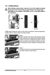
...with two or four memory modules, it is recommended that you install them in only one DDR2 memory module is recommended that the motherboard supports the memory. A memory module can be installed, it is recommended that memory of the memory. Enabling Dual Channel memory ... enabled if only one direction. Dual Channel mode cannot be used and installed in Dual Channel mode. 1. Hardware Installation If you begin to GIGABYTE's website for optimum performance. - 15 - The four DDR2 memory sockets are unable to prevent hardware damage. • Memory modules have a...
...with two or four memory modules, it is recommended that you install them in only one DDR2 memory module is recommended that the motherboard supports the memory. A memory module can be installed, it is recommended that memory of the memory. Enabling Dual Channel memory ... enabled if only one direction. Dual Channel mode cannot be used and installed in Dual Channel mode. 1. Hardware Installation If you begin to GIGABYTE's website for optimum performance. - 15 - The four DDR2 memory sockets are unable to prevent hardware damage. • Memory modules have a...
Manual
Page 16
... orientation of the memory, push down on the socket. Spread the retaining clips at both ends of the socket will snap into the memory socket. GA-M720-ES3 Motherboard - 16 - Step 2: The clips at both ends of the memory socket. Follow the steps below to install DDR2 DIMMs on the left, place .... Place the memory module on the memory and insert it can only fit in the memory sockets. As indicated in the picture on this motherboard. DDR2 DIMMs are not compatible to DDR DIMMs. Be sure to correctly install your fingers on the top edge of the memory module. Notch...
... orientation of the memory, push down on the socket. Spread the retaining clips at both ends of the socket will snap into the memory socket. GA-M720-ES3 Motherboard - 16 - Step 2: The clips at both ends of the memory socket. Follow the steps below to install DDR2 DIMMs on the left, place .... Place the memory module on the memory and insert it can only fit in the memory sockets. As indicated in the picture on this motherboard. DDR2 DIMMs are not compatible to DDR DIMMs. Be sure to correctly install your fingers on the top edge of the memory module. Notch...

Manual
Page 17
... turn off the computer and unplug the power cord from the power outlet before you begin to install an expansion card: • Make sure the motherboard supports the expansion card. Carefully read the manual that supports your expansion card(s). 7. Example: Installing and Removing a PCI Express x16 Graphics Card: • Installing a Graphics...
... turn off the computer and unplug the power cord from the power outlet before you begin to install an expansion card: • Make sure the motherboard supports the expansion card. Carefully read the manual that supports your expansion card(s). 7. Example: Installing and Removing a PCI Express x16 Graphics Card: • Installing a Graphics...

Manual
Page 18
... provides digital audio out to a back panel connector, first remove the cable from your device and then remove it from the connector. GA-M720-ES3 Motherboard - 18 - Before using this feature, ensure that supports digital optical audio. Use this feature, ensure that supports digital coaxial audio. Connection...short inside the cable connector. USB Port The USB port supports the USB 2.0/1.1 specification. Do not rock it straight out from the motherboard. • When removing the cable, pull it side to side to an external audio system that your audio system provides a coaxial...
... provides digital audio out to a back panel connector, first remove the cable from your device and then remove it from the connector. GA-M720-ES3 Motherboard - 18 - Before using this feature, ensure that supports digital optical audio. Use this feature, ensure that supports digital coaxial audio. Connection...short inside the cable connector. USB Port The USB port supports the USB 2.0/1.1 specification. Do not rock it straight out from the motherboard. • When removing the cable, pull it side to side to an external audio system that your audio system provides a coaxial...
Manual
Page 20
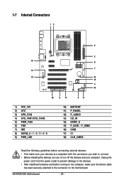
... devices are compliant with the connectors you wish to connect. • Before installing the devices, be sure to turn off the devices and your computer. GA-M720-ES3 Motherboard - 20 - 1-7 Internal Connectors 13 5 2 12 8 7 14 13 10 15 4 18 16 6 17 9 11 1) ATX_12V 2) ATX 3) CPU_FAN 4) SYS_FAN1/SYS_FAN2 5) PWR_FAN 6) FDD 7) IDE 8) SATA2_0 / 1 / 2 / 3 / 4 / 5 9) PWR_LED 10) BATTERY...
... devices are compliant with the connectors you wish to connect. • Before installing the devices, be sure to turn off the devices and your computer. GA-M720-ES3 Motherboard - 20 - 1-7 Internal Connectors 13 5 2 12 8 7 14 13 10 15 4 18 16 6 17 9 11 1) ATX_12V 2) ATX 3) CPU_FAN 4) SYS_FAN1/SYS_FAN2 5) PWR_FAN 6) FDD 7) IDE 8) SATA2_0 / 1 / 2 / 3 / 4 / 5 9) PWR_LED 10) BATTERY...

Manual
Page 21
... (500W or greater). Before connecting the power connector, first make sure the power supply is turned off and all the components on the motherboard. Connect the power supply cable to the CPU. The 12V power connector mainly supplies power to the power connector in the correct orientation. ...power supply cable into pins under the protective cover when using a 2x12 power supply, remove the protective cover from the main power connector on the motherboard. If the 12V power connector is not connected, the computer will not start. • To meet expansion requirements, it is recommended that a...
... (500W or greater). Before connecting the power connector, first make sure the power supply is turned off and all the components on the motherboard. Connect the power supply cable to the CPU. The 12V power connector mainly supplies power to the power connector in the correct orientation. ...power supply cable into pins under the protective cover when using a 2x12 power supply, remove the protective cover from the main power connector on the motherboard. If the 12V power connector is not connected, the computer will not start. • To meet expansion requirements, it is recommended that a...
Manual
Page 22
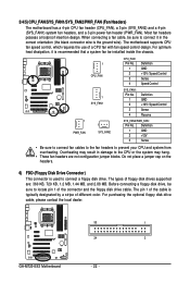
...fan with fan speed control design. For purchasing the optional floppy disk drive cable, please contact the local dealer. 33 1 34 2 GA-M720-ES3 Motherboard - 22 - Overheating may result in the correct orientation (the black connector wire is recommended that a system fan be installed inside the...6) FDD (Floppy Disk Drive Connector) This connector is used to connect it is the ground wire). 3/4/5) CPU_FAN/SYS_FAN1/SYS_FAN2/PWR_FAN (Fan Headers) The motherboard has a 4-pin CPU fan header (CPU_FAN), a 3-pin (SYS_FAN2) and a 4-pin (SYS_FAN1) system fan headers, and a 3-pin power fan...
...fan with fan speed control design. For purchasing the optional floppy disk drive cable, please contact the local dealer. 33 1 34 2 GA-M720-ES3 Motherboard - 22 - Overheating may result in the correct orientation (the black connector wire is recommended that a system fan be installed inside the...6) FDD (Floppy Disk Drive Connector) This connector is used to connect it is the ground wire). 3/4/5) CPU_FAN/SYS_FAN1/SYS_FAN2/PWR_FAN (Fan Headers) The motherboard has a 4-pin CPU fan header (CPU_FAN), a 3-pin (SYS_FAN2) and a 4-pin (SYS_FAN1) system fan headers, and a 3-pin power fan...
Manual
Page 24
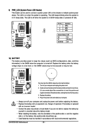
... the power cord before replacing the battery. • Replace the battery with local environmental regulations. Danger of the battery holder, making them short for one . GA-M720-ES3 Motherboard - 24 - The LED is off . The LED is on the chassis to touch the positive and negative terminals of explosion if the battery is turned...
... the power cord before replacing the battery. • Replace the battery with local environmental regulations. Danger of the battery holder, making them short for one . GA-M720-ES3 Motherboard - 24 - The LED is off . The LED is on the chassis to touch the positive and negative terminals of explosion if the battery is turned...


