
Manual
Page 3
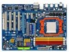
... set-up of the motherboard is 1.0. For example, "REV: 1.0" means the revision of the product, read the Quick Installation Guide included with the product. For detailed product information, carefully read the User's Manual. For instructions on how to assist in the use GIGABYTE's unique features, read or download the information on/from the Support&Downloads\Motherboard\Technology Guide page on your motherboard revision before updating motherboard BIOS, drivers...
... set-up of the motherboard is 1.0. For example, "REV: 1.0" means the revision of the product, read the Quick Installation Guide included with the product. For detailed product information, carefully read the User's Manual. For instructions on how to assist in the use GIGABYTE's unique features, read or download the information on/from the Support&Downloads\Motherboard\Technology Guide page on your motherboard revision before updating motherboard BIOS, drivers...
Manual
Page 4
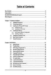
...of Contents Box Contents ...6 OptionalItems...6 GA-M720-ES3 Motherboard Layout 7 Block Diagram...8 Chapter 1 Hardware Installation 9 1-1 Installation Precautions 9 1-2 Product Specifications 10 1-3 Installing the CPU and CPU Cooler 12 1-3-1 Installing the CPU 12 1-3-2 Installing the CPU Cooler 14 1-4 Installing the Memory 15 1-4-1 Dual Channel Memory Configuration 15 1-4-2 Installing a Memory 16 1-5 Installing an Expansion Card 17 1-6 Back Panel Connectors 18 1-7 Internal Connectors 20 Chapter 2 BIOS Setup 31 2-1 Startup Screen 32 2-2 The Main Menu 33 2-3 MB Intelligent Tweaker...
...of Contents Box Contents ...6 OptionalItems...6 GA-M720-ES3 Motherboard Layout 7 Block Diagram...8 Chapter 1 Hardware Installation 9 1-1 Installation Precautions 9 1-2 Product Specifications 10 1-3 Installing the CPU and CPU Cooler 12 1-3-1 Installing the CPU 12 1-3-2 Installing the CPU Cooler 14 1-4 Installing the Memory 15 1-4-1 Dual Channel Memory Configuration 15 1-4-2 Installing a Memory 16 1-5 Installing an Expansion Card 17 1-6 Back Panel Connectors 18 1-7 Internal Connectors 20 Chapter 2 BIOS Setup 31 2-1 Startup Screen 32 2-2 The Main Menu 33 2-3 MB Intelligent Tweaker...

Manual
Page 5
... Utilities 62 4-2-1 Updating the BIOS with the Q-Flash Utility 62 4-2-2 Updating the BIOS with the @BIOS Utility 65 4-3 EasyTune 6 ...66 4-4 Easy Energy Saver 67 Chapter 5 Appendix ...69 5-1 Configuring SATA Hard Drive(s 69 5-1-1 Configuring the Onboard SATA Controller 69 5-1-2 Making a SATA RAID/AHCI Driver Diskette for Windows XP 74 5-1-3 Installing the SATA RAID Driver and Operating System 75 5-2 Configuring Audio Input and Output 79 5-2-1 Configuring 2/4/5.1/7.1-Channel Audio 79 5-2-2 Configuring S/PDIF Out 81 5-2-3 Configuring Microphone Recording 82 5-2-4 Using the Sound...
... Utilities 62 4-2-1 Updating the BIOS with the Q-Flash Utility 62 4-2-2 Updating the BIOS with the @BIOS Utility 65 4-3 EasyTune 6 ...66 4-4 Easy Energy Saver 67 Chapter 5 Appendix ...69 5-1 Configuring SATA Hard Drive(s 69 5-1-1 Configuring the Onboard SATA Controller 69 5-1-2 Making a SATA RAID/AHCI Driver Diskette for Windows XP 74 5-1-3 Installing the SATA RAID Driver and Operating System 75 5-2 Configuring Audio Input and Output 79 5-2-1 Configuring 2/4/5.1/7.1-Channel Audio 79 5-2-2 Configuring S/PDIF Out 81 5-2-3 Configuring Microphone Recording 82 5-2-4 Using the Sound...
Manual
Page 10
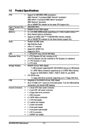
... latest memory support list.) Realtek ALC888 codec High Definition Audio 2/4/5.1/7.1-channel Support for S/PDIF Out Support for SATA RAID 0, RAID 1, RAID 5, RAID 10, and JBOD iTE IT8720 chip: - 1 x floppy disk drive connector supporting up to the internal USB headers) 1 x 24-pin ATX main power connector 1 x 4-pin ATX 12V power connector 1 x floppy disk drive connector 1 x IDE connector 6 x SATA 3Gb/s connectors 1 x CPU fan header 2 x system fan headers 1 x power fan header 1 x front panel header 1 x front panel audio header 1 x CD In connector 1 x S/PDIF Out header GA-M720-ES3 Motherboard...
... latest memory support list.) Realtek ALC888 codec High Definition Audio 2/4/5.1/7.1-channel Support for S/PDIF Out Support for SATA RAID 0, RAID 1, RAID 5, RAID 10, and JBOD iTE IT8720 chip: - 1 x floppy disk drive connector supporting up to the internal USB headers) 1 x 24-pin ATX main power connector 1 x 4-pin ATX 12V power connector 1 x floppy disk drive connector 1 x IDE connector 6 x SATA 3Gb/s connectors 1 x CPU fan header 2 x system fan headers 1 x power fan header 1 x front panel header 1 x front panel audio header 1 x CD In connector 1 x S/PDIF Out header GA-M720-ES3 Motherboard...

Manual
Page 17
.... If necessary, go to BIOS Setup to correctly install your expansion card(s). 7. PCI Express x1 Slot PCI Express x16 Slot PCI Slot Follow the steps below to make any required BIOS changes for your expansion card in your expansion card. • Always turn off the computer and unplug the power cord from the chassis back panel. 2. Make sure the card is fully inserted into the slot. 4. 1-5 Installing an Expansion Card Read the following guidelines...
.... If necessary, go to BIOS Setup to correctly install your expansion card(s). 7. PCI Express x1 Slot PCI Express x16 Slot PCI Slot Follow the steps below to make any required BIOS changes for your expansion card in your expansion card. • Always turn off the computer and unplug the power cord from the chassis back panel. 2. Make sure the card is fully inserted into the slot. 4. 1-5 Installing an Expansion Card Read the following guidelines...
Manual
Page 22
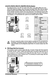
... a jumper cap on the headers. 6) FDD (Floppy Disk Drive Connector) This connector is the ground wire). Before connecting a floppy disk drive, be installed inside the chassis. 1 CPU_FAN CPU_FAN: Pin No. 1 2 3 4 Definition GND +12V / Speed Control Sense Speed Control 1 SYS_FAN1 SYS_FAN1: Pin No. 1 2 3 4 Definition GND +12V / Speed Control Sense Reserve 1 PWR_FAN 1 SYS_FAN2 SYS_FAN2/PWR_FAN: Pin No. Most fan headers possess a foolproof insertion design. The motherboard supports CPU fan speed control, which requires the use of the connector and the floppy disk drive cable. When...
... a jumper cap on the headers. 6) FDD (Floppy Disk Drive Connector) This connector is the ground wire). Before connecting a floppy disk drive, be installed inside the chassis. 1 CPU_FAN CPU_FAN: Pin No. 1 2 3 4 Definition GND +12V / Speed Control Sense Speed Control 1 SYS_FAN1 SYS_FAN1: Pin No. 1 2 3 4 Definition GND +12V / Speed Control Sense Reserve 1 PWR_FAN 1 SYS_FAN2 SYS_FAN2/PWR_FAN: Pin No. Most fan headers possess a foolproof insertion design. The motherboard supports CPU fan speed control, which requires the use of the connector and the floppy disk drive cable. When...
Manual
Page 29
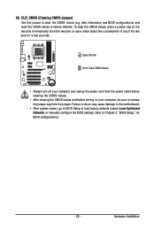
... to clear the CMOS values (e.g. Hardware Installation Failure to do so may cause damage to the motherboard. • After system restart, go to BIOS Setup to load factory defaults (select Load Optimized Defaults) or manually configure the BIOS settings (refer to factory defaults. 18) CLR_CMOS (Clearing CMOS Jumper) Use this jumper to remove the jumper cap from the power outlet before clearing the CMOS values. • After clearing the CMOS values and before turning on the two pins to temporarily short...
... to clear the CMOS values (e.g. Hardware Installation Failure to do so may cause damage to the motherboard. • After system restart, go to BIOS Setup to load factory defaults (select Load Optimized Defaults) or manually configure the BIOS settings (refer to factory defaults. 18) CLR_CMOS (Clearing CMOS Jumper) Use this jumper to remove the jumper cap from the power outlet before clearing the CMOS values. • After clearing the CMOS values and before turning on the two pins to temporarily short...

Manual
Page 34
... CPU, memory, etc. Standard CMOS Features Use this menu to configure the system time and date, hard drive types, floppy disk drive types, and the type of errors that stop the system boot, etc. Advanced BIOS Features Use this menu to configure the device boot order, advanced features available on the CPU, and the primary display adapter. Integrated Peripherals Use this menu to configure all peripheral devices, such as IDE, SATA, USB, integrated audio, and integrated LAN, etc. Power Management Setup Use...
... CPU, memory, etc. Standard CMOS Features Use this menu to configure the system time and date, hard drive types, floppy disk drive types, and the type of errors that stop the system boot, etc. Advanced BIOS Features Use this menu to configure the device boot order, advanced features available on the CPU, and the primary display adapter. Integrated Peripherals Use this menu to configure all peripheral devices, such as IDE, SATA, USB, integrated audio, and integrated LAN, etc. Power Management Setup Use...

Manual
Page 42
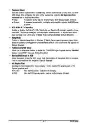
...exit this feature. GA-M720-ES3 Motherboard - 42 - First/Second/Third Boot Device Specifies the boot order from the installed hard drives. 2-5 Advanced BIOS Features CMOS Setup Utility-Copyright (C) 1984-2009 Award Software Advanced BIOS Features AMD C1E Support Virtualization Patch AMD TLB Erratum (Note) AMD K8 Cool&Quiet control Hard Disk Boot Priority First Boot Device Second Boot Device Third Boot Device Password Check HDD S.M.A.R.T. Options are: Floppy, LS120, Hard Disk, CDROM, ZIP, USB-FDD, USB-ZIP, USB-CDROM, USB-HDD, Legacy LAN, Disabled. (Note) This item...
...exit this feature. GA-M720-ES3 Motherboard - 42 - First/Second/Third Boot Device Specifies the boot order from the installed hard drives. 2-5 Advanced BIOS Features CMOS Setup Utility-Copyright (C) 1984-2009 Award Software Advanced BIOS Features AMD C1E Support Virtualization Patch AMD TLB Erratum (Note) AMD K8 Cool&Quiet control Hard Disk Boot Priority First Boot Device Second Boot Device Third Boot Device Password Check HDD S.M.A.R.T. Options are: Floppy, LS120, Hard Disk, CDROM, ZIP, USB-FDD, USB-ZIP, USB-CDROM, USB-HDD, Legacy LAN, Disabled. (Note) This item...
Manual
Page 43
... configuring this image file. (Default: Disabled) Init Display First Specifies the first initiation of the hard drive and to issue warnings when a third party hardware monitor utility is installed. (Default: Disabled) Away Mode Enables or disables Away Mode in Windows XP Media Center operating system. HDD S.M.A.R.T. Sets the PCI Express graphics card as the first display. BIOS Setup This feature allows your hard drive. If the system BIOS is required for booting the system and for entering the BIOS Setup program. Away Mode allows...
... configuring this image file. (Default: Disabled) Init Display First Specifies the first initiation of the hard drive and to issue warnings when a third party hardware monitor utility is installed. (Default: Disabled) Away Mode Enables or disables Away Mode in Windows XP Media Center operating system. HDD S.M.A.R.T. Sets the PCI Express graphics card as the first display. BIOS Setup This feature allows your hard drive. If the system BIOS is required for booting the system and for entering the BIOS Setup program. Away Mode allows...

Manual
Page 44
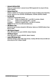
... CMOS Setup Utility-Copyright (C) 1984-2009 Award Software Integrated Peripherals On-Chip IDE Channel NV SATA Controller Onchip SATA Mode Onboard Audio Function Onboard LAN Control SMART LAN Onboard LAN Boot ROM Onboard Serial Port OnChip USB USB Memory Type USB Keyboard Support USB Mouse Support Legacy USB storage detect [Enabled] [Enabled] [IDE] [Auto] [Enabled] [Press Enter] [Disabled] [3F8/IRQ4] [V1.1+V2.0] [SHADOW] [Disabled] [Disabled] [Enabled] Item Help Menu Level Move Enter: Select F5: Previous Values +/-/PU/PD: Value F10: Save F6: Fail-Safe Defaults...
... CMOS Setup Utility-Copyright (C) 1984-2009 Award Software Integrated Peripherals On-Chip IDE Channel NV SATA Controller Onchip SATA Mode Onboard Audio Function Onboard LAN Control SMART LAN Onboard LAN Boot ROM Onboard Serial Port OnChip USB USB Memory Type USB Keyboard Support USB Mouse Support Legacy USB storage detect [Enabled] [Enabled] [IDE] [Auto] [Enabled] [Press Enter] [Disabled] [3F8/IRQ4] [V1.1+V2.0] [SHADOW] [Disabled] [Disabled] [Enabled] Item Help Menu Level Move Enter: Select F5: Previous Values +/-/PU/PD: Value F10: Save F6: Fail-Safe Defaults...
Manual
Page 46
...) Legacy USB storage detect Determines whether to activate the boot ROM integrated with the onboard LAN chip. (Default: Disabled) Onboard Serial Port Enables or disables the first serial port and specifies its base I/O address and corresponding interrupt. Disabled Disables the integrated USB 1.1 and USB 2.0 controllers. USB Memory Type Specifies the type of the USB functionalities below. Onboard LAN Boot ROM Allows you to decide whether to detect USB storage devices, including USB flash drives and USB hard drives during the POST. (Default: Enabled) GA-M720-ES3 Motherboard...
...) Legacy USB storage detect Determines whether to activate the boot ROM integrated with the onboard LAN chip. (Default: Disabled) Onboard Serial Port Enables or disables the first serial port and specifies its base I/O address and corresponding interrupt. Disabled Disables the integrated USB 1.1 and USB 2.0 controllers. USB Memory Type Specifies the type of the USB functionalities below. Onboard LAN Boot ROM Allows you to decide whether to detect USB storage devices, including USB flash drives and USB hard drives during the POST. (Default: Enabled) GA-M720-ES3 Motherboard...
Manual
Page 50
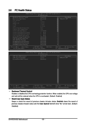
... will show "No" at next boot. (Default: Disabled) GA-M720-ES3 Motherboard - 50 - Enabled clears the record of previous chassis intrusion status. 2-9 PC Health Status CMOS Setup Utility-Copyright (C) 1984-2009 Award Software PC Health Status Hardware Thermal Control Reset Case Open Status Case Opened Vcore DDR2 1.8V +3.3V +12V Current System Temperature Current CPU Temperature Current CPU FAN Speed Current SYSTEM FAN1 Speed Current SYSTEM FAN2 Speed Current POWER FAN Speed System Warning Temperature CPU Warning Temperature CPU FAN Fail Warning SYSTEM FAN1 Fail...
... will show "No" at next boot. (Default: Disabled) GA-M720-ES3 Motherboard - 50 - Enabled clears the record of previous chassis intrusion status. 2-9 PC Health Status CMOS Setup Utility-Copyright (C) 1984-2009 Award Software PC Health Status Hardware Thermal Control Reset Case Open Status Case Opened Vcore DDR2 1.8V +3.3V +12V Current System Temperature Current CPU Temperature Current CPU FAN Speed Current SYSTEM FAN1 Speed Current SYSTEM FAN2 Speed Current POWER FAN Speed System Warning Temperature CPU Warning Temperature CPU FAN Fail Warning SYSTEM FAN1 Fail...

Manual
Page 51
... sound if the CPU/system/power fan is set Reset Case Open Status to Enabled, save the settings to the motherboard CI header. BIOS Setup Current Voltage(V) Vcore/DDR2 1.8V/+3.3V/+12V Displays the current system voltages. When system/CPU temperature ex- Case Opened Displays the detection status of CPU fan installed and sets the optimal CPU fan control mode. (Default) Voltage Sets Voltage mode for a 3-pin CPU fan. This item is configurable only if CPU Smart FAN Control is not connected or fails. Auto Lets BIOS autodetect the type of the chassis intrusion detection device...
... sound if the CPU/system/power fan is set Reset Case Open Status to Enabled, save the settings to the motherboard CI header. BIOS Setup Current Voltage(V) Vcore/DDR2 1.8V/+3.3V/+12V Displays the current system voltages. When system/CPU temperature ex- Case Opened Displays the detection status of CPU fan installed and sets the optimal CPU fan control mode. (Default) Voltage Sets Voltage mode for a 3-pin CPU fan. This item is configurable only if CPU Smart FAN Control is not connected or fails. Auto Lets BIOS autodetect the type of the chassis intrusion detection device...
Manual
Page 62
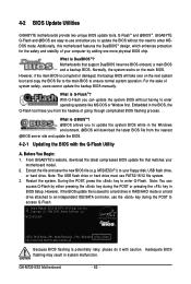
... copy the BIOS file to the main BIOS to access Q-Flash. During the POST, press the key to an independent IDE/SATA controller, use the key during the POST or pressing the key in system malfunction. However, if the BIOS update file is potentially risky, please do it with the Q-Flash Utility A. M720-ES3 E3c . . . . : BIOS Setup : XpressRecovery2 : Boot Menu : Qflash 06/10/2009-NF-MCP78-6A61OG09C-00 Because BIOS flashing is saved to a hard drive in RAID/AHCI mode or a hard drive attached to enter Q-Flash.
... copy the BIOS file to the main BIOS to access Q-Flash. During the POST, press the key to an independent IDE/SATA controller, use the key during the POST or pressing the key in system malfunction. However, if the BIOS update file is potentially risky, please do it with the Q-Flash Utility A. M720-ES3 E3c . . . . : BIOS Setup : XpressRecovery2 : Boot Menu : Qflash 06/10/2009-NF-MCP78-6A61OG09C-00 Because BIOS flashing is saved to a hard drive in RAID/AHCI mode or a hard drive attached to enter Q-Flash.

Manual
Page 63
... not remove the floppy disk, USB flash drive, or hard drive when the system is saved. Select the BIOS update file and press . Step 3: When the update process is saved to a hard drive in RAID/AHCI mode or a hard drive attached to an independent IDE/SATA controller, use the key during the POST to the main menu. In the main menu of the system reading the BIOS file from Drive Sa0vefilBeI(Os)SfotounDdrive :Move ESC:Reset :Power Off Total size : 0 Free size : 0 3. appears, press to update BIOS...
... not remove the floppy disk, USB flash drive, or hard drive when the system is saved. Select the BIOS update file and press . Step 3: When the update process is saved to a hard drive in RAID/AHCI mode or a hard drive attached to an independent IDE/SATA controller, use the key during the POST to the main menu. In the main menu of the system reading the BIOS file from Drive Sa0vefilBeI(Os)SfotounDdrive :Move ESC:Reset :Power Off Total size : 0 Free size : 0 3. appears, press to update BIOS...
Manual
Page 66
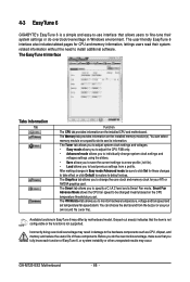
... graphics card. Smart Fan Advance Mode allows the CPU fan speed to change system clock settings and voltages settings using the sliders. • Save allows you to save the current settings to a new profile (.txt file). • Load allows you to be sure to click Set for these components. The Graphics tab allows you to install additional software. Grayed-out area(s) indicates that allows users to specify a C.I.A.2 level and a Smart Fan mode. Before you do overclock...
... graphics card. Smart Fan Advance Mode allows the CPU fan speed to change system clock settings and voltages settings using the sliders. • Save allows you to save the current settings to a new profile (.txt file). • Load allows you to be sure to click Set for these components. The Graphics tab allows you to install additional software. Grayed-out area(s) indicates that allows users to specify a C.I.A.2 level and a Smart Fan mode. Before you do overclock...

Manual
Page 69
Configure SATA controller mode in RAID BIOS. (Note 1) D. Then connect the power connector from your power supply to the hard drive. (Note 1) Skip this step if you use two hard drives with identical model and capacity). C . If you do not want to create RAID, you may prepare only one end of the SATA signal cable to the rear of the SATA hard drive and the other end to available SATA port on the SATA controller. (Note 2) Required when...
Configure SATA controller mode in RAID BIOS. (Note 1) D. Then connect the power connector from your power supply to the hard drive. (Note 1) Skip this step if you use two hard drives with identical model and capacity). C . If you do not want to create RAID, you may prepare only one end of the SATA signal cable to the rear of the SATA hard drive and the other end to available SATA port on the SATA controller. (Note 2) Required when...

Manual
Page 74
... MCP78 Series AHCI Driver (XP64) for Windows XP 64-bit. Your system will open similar to that is/are configured to RAID/AHCI mode, you need to the floppy disk. For installing Windows Vista, please directly load the SATA RAID driver from the startup disk. Step 1: Insert the prepared startup disk and motherboard driver disk in Figure 2. A command prompt window will then automatically zip and transfer this driver file to install the SATA controller driver during the Windows setup process. 5-1-2 Making a SATA RAID/AHCI Driver...
... MCP78 Series AHCI Driver (XP64) for Windows XP 64-bit. Your system will open similar to that is/are configured to RAID/AHCI mode, you need to the floppy disk. For installing Windows Vista, please directly load the SATA RAID driver from the startup disk. Step 1: Insert the prepared startup disk and motherboard driver disk in Figure 2. A command prompt window will then automatically zip and transfer this driver file to install the SATA controller driver during the Windows setup process. 5-1-2 Making a SATA RAID/AHCI Driver...

Manual
Page 85
... the battery holder to stop supplying power to enter BIOS Setup. Press to the CMOS, which will clear the CMOS values after the computer shuts down ? A: The following Award BIOS beep code descriptions may help you identify possible computer problems. (For reference only.) 1 short: System boots successfully 2 short: CMOS setting error 1 long, 1 short: Memory or motherboard error 1 long, 2 short: Monitor or graphics card error 1 long, 3 short: Keyboard error 1 long, 9 short: BIOS ROM error Continuous long beeps: Graphics card not inserted properly Continuous short beeps: Power error - 85...
... the battery holder to stop supplying power to enter BIOS Setup. Press to the CMOS, which will clear the CMOS values after the computer shuts down ? A: The following Award BIOS beep code descriptions may help you identify possible computer problems. (For reference only.) 1 short: System boots successfully 2 short: CMOS setting error 1 long, 1 short: Memory or motherboard error 1 long, 2 short: Monitor or graphics card error 1 long, 3 short: Keyboard error 1 long, 9 short: BIOS ROM error Continuous long beeps: Graphics card not inserted properly Continuous short beeps: Power error - 85...


